Table of Contents
Advertisement
Quick Links
Advertisement
Table of Contents

Related Manuals for IFM ecomatController


Summary of Contents for IFM ecomatController
- Page 1 Installation instructions ecomatController CR720S CR721S P_MZ_e100_0093...
-
Page 2: Table Of Contents
CR720S/CR721S Contents 1 Preliminary note � � � � � � � � � � � � � � � � � � � � � � � � � � � � � � � � � � � � � � � � � � � � � � � � � 4 1�1 Explanation of symbols �... - Page 3 CR720S/CR721S 7�1�5 Connectors� � � � � � � � � � � � � � � � � � � � � � � � � � � � � � � � � � � � � � � � � � � � 30 7�1�6 Connector A / wiring �...
-
Page 4: Preliminary Note
CR720S/CR721S 1 Preliminary note This document applies to devices of the type "ecomatController" (art� no�: CR720S/CR721S)� It is part of the device� This document is intended for specialists� These specialists are people who are qualified by their appropriate training and their experience to see risks and to avoid possible hazards that may be caused during operation or maintenance of the device�... -
Page 5: Safety Instructions
The connection terminals may only be supplied with the signals indicated in the technical data and/or on the device label and only the approved accessories from ifm electronic gmbh may be connected� 2.4 Housing temperature As described in the technical specifications below the device can be operated in a wide ambient temperature range�... -
Page 6: 2�5 Tampering With The Device
Protect the controller against weld slag� 3 Functions and features The freely programmable controllers of the "ecomatController" series are rated for use under difficult conditions (e�g� extended temperature range, strong vibration, intensive EMC interference)�... -
Page 7: Installation
CR720S/CR721S 4 Installation 4.1 Fastening P_MZ_e100_0093 Original S Scale: 1:2 ► Fix the controller to a flat surface using 4 galvanized M6 screws� Tightening torque: 10 ±2 68,4 Total height with the attached Installation connector� NOTE To avoid contact corrosion between the mounting screws and the module EPS Sour housing, do not use any stainless steel screws or nickel-plated screws�... -
Page 8: 4�2 Installation Position
CR720S/CR721S 4.2 Installation position In wet environments, install the controller ensuring that no liquid remains on the connectors� 4.3 Mounting surface NOTE The housing must not be exposed to any torsional forces or mechanical stress� ► Use compensating elements if there is no flat mounting surface available�... -
Page 9: Electrical Connection
CR720S/CR721S 5 Electrical connection 5.1 Wiring Wiring (→ 7 Technical data) Only connect the connector pins as shown in the pin layout� Unspecified connector pins remain unconnected� P_MZ_e100_0093 Original Scale Drawing (MTD) ► Connect all indicated supply cables and GND terminals�... -
Page 10: 5�3 Fuses
CR720S/CR721S To ensure the protection of the device against electrical interference and the safe function of the device, the housing must be connected to the ground / body of the vehicle in the shortest possible way� ► Connect the device to the ground of the vehicle using the M4 self-tapping screw (included)�... -
Page 11: 5�4�1 Gnd Connections
CR720S/CR721S WARNING The linking of connections in the plug is not permitted and can affect the safety of operators and machinery� ► Basically all supply and signal cables must be laid separately� ► Connect supply and ground cables to the controller and the sensors/actuators via the respective common star point�... -
Page 12: 5�5 Analogue Inputs
CR720S/CR721S 5.5 Analogue inputs supply input input nn GND controller Shield Connection of the analogue inputs (A) ► Connect GND to the GND of the signal source� Do not connect GND to other GND connectors or to the GND star point�... -
Page 13: 5�6 Resistor Inputs
CR720S/CR721S 5.6 Resistor inputs supply input input nn GND controller Shield Connection of the resistor inputs (R) ► Connect GND to the GND of the signal source� Do not connect GND to other GND connectors or to the GND star point�... -
Page 14: 5�7 High Side Digital Inputs (Cso)
CR720S/CR721S 5.7 High side digital inputs (CSO) supply input , FRQ input , FRQ nn GND controller Shield Connection of the high side inputs (B , FRQ 1: Connection for 3-wire sensors ► Connect the GND of the signal source with the common GND star point�Do not... -
Page 15: 5�8 Analogue Outputs
CR720S/CR721S 5.8 Analogue outputs supply Con. A A (0...10 V) load A (0...10 V) load Con. B Con. B Con. A controller Shield Connection of the analogue outputs (A) ► Connect the GND of the load to GND �... -
Page 16: 5�9 Low Side Digital Outputs (Csi) / H-Bridge
CR720S/CR721S 5.9 Low side digital outputs (CSI) / H-bridge supply load load load controller load Shield Connection of the low side digital outputs (PWM ► Supply low-side outputs (B ) via a high side output (B ) of the same output group�... -
Page 17: 5�10 Mixed Operation (12 V / 24 V)
CR720S/CR721S 5.10 Mixed operation (12 V / 24 V) supply 24 V sensor input output load sensor input output load sensor input output load controller Shield Example connection to 24 V and 12 V power supply combined The operation of the output groups is possible with different supply voltages�... -
Page 18: Set-Up
6.3 Getting started ► Check if the pre-installed, latest version of the ifm operating system is required� If necessary, download and install a different version via TFTP� ► Connect the device to the notebook/PC via the Ethernet interface�... -
Page 19: 6�4 Required Documentation
● Programming manual CODESYS V3�5 (alternatively as online help) The manuals can be downloaded from the internet: www.ifm.com → Search → Art. no. → Documents & downloads CODESYS online help: www.ifm.com → Service → Download → Control systems* *) Download area with registration... -
Page 20: Technical Data
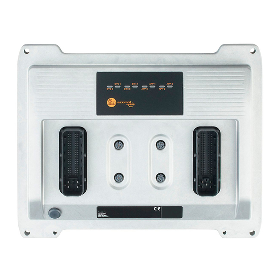
Current consumption VBB max� 600 mA at 12 V max� 400 mA at 24 V ifm electronic gmbh ● Friedrichstraße 1 ● 45128 Essen We reserve the right to make technical alterations without prior notice! CR720S / page 1 22 Nov� 2017... - Page 21 2 x LED (G) for ETH0 and ETH1 Application LED 4 x three-colour LED (R/G/B) for APP0, APP1, APP2 and APP3 ifm electronic gmbh ● Friedrichstraße 1 ● 45128 Essen We reserve the right to make technical alterations without prior notice! CR720S / page 2...
- Page 22 APP3 mable blue status display of the application, freely program- mable ifm electronic gmbh ● Friedrichstraße 1 ● 45128 Essen We reserve the right to make technical alterations without prior notice! CR720S / page 3 22 Nov� 2017...
-
Page 23: 7�1�2 Test Standards And Regulations
10���500 Hz; 0�72 mm/10 g; 10 cycles/axis ISO 16750-3 Bump 30 g/6 ms; 24,000 shocks * in preparation ifm electronic gmbh ● Friedrichstraße 1 ● 45128 Essen We reserve the right to make technical alterations without prior notice! CR720S / page 4 22 Nov� 2017... -
Page 24: 7�1�3 Connectors A And B / Input Characteristics
Switch-on level > 0�7 VBB Switch-off level < 0�3 VBB Accuracy ± 10 µs ifm electronic gmbh ● Friedrichstraße 1 ● 45128 Essen We reserve the right to make technical alterations without prior notice! CR720S / page 5 22 Nov� 2017... - Page 25 ± 1 % Range diagnostics min - max� 1 V / 0�95 VBB (default) ifm electronic gmbh ● Friedrichstraße 1 ● 45128 Essen We reserve the right to make technical alterations without prior notice! CR720S / page 6 22 Nov� 2017...
- Page 26 0���3 supply sensors/module ifm electronic gmbh ● Friedrichstraße 1 ● 45128 Essen We reserve the right to make technical alterations without prior notice! CR720S / page 7 22 Nov� 2017...
-
Page 27: 7�1�4 Connectors A And B / Output Characteristics
Digital output (B Range diagnostics min - max� 0 A / 4 A (default) ifm electronic gmbh ● Friedrichstraße 1 ● 45128 Essen We reserve the right to make technical alterations without prior notice! CR720S / page 8 22 Nov� 2017... - Page 28 ± 1�5 % FS (for inductive loads) Range diagnostics min - max� 0 A / 2�5 A (default) ifm electronic gmbh ● Friedrichstraße 1 ● 45128 Essen We reserve the right to make technical alterations without prior notice! CR720S / page 9...
- Page 29 (CSI) pulse-width modulation current-controlled supply output group via semiconductor switch 0���3 supply sensors/module ifm electronic gmbh ● Friedrichstraße 1 ● 45128 Essen We reserve the right to make technical alterations without prior notice! CR720S / page 10 22 Nov� 2017...
- Page 30 EPS Source Product Scale D Product Scale D Frame Size: 80 Frame Size: 80 ifm electronic gmbh ● Friedrichstraße 1 ● 45128 Essen We reserve the right to make technical alterations without prior notice! CR720S / page 11 22 Nov� 2017...
-
Page 31: 7�2�6 Connector A / Wiring
0���3 supply sensors/module ifm electronic gmbh ● Friedrichstraße 1 ● 45128 Essen We reserve the right to make technical alterations without prior notice! CR720S / page 12 22 Nov� 2017... - Page 32 0���3 supply sensors/module ifm electronic gmbh ● Friedrichstraße 1 ● 45128 Essen We reserve the right to make technical alterations without prior notice! CR720S / page 13 22 Nov� 2017...
- Page 33 Current consumption VBB max� 600 mA at 12 V max� 400 mA at 24 V ifm electronic gmbh ● Friedrichstraße 1 ● 45128 Essen We reserve the right to make technical alterations without prior notice! CR721S / page 1 22 Nov� 2017...
- Page 34 2 x LED (G) for ETH0 and ETH1 Application LED 4 x three-colour LED (R/G/B) for APP0, APP1, APP2 and APP3 ifm electronic gmbh ● Friedrichstraße 1 ● 45128 Essen We reserve the right to make technical alterations without prior notice! CR721S / page 2...
- Page 35 APP3 mable blue status display of the application, freely program- mable ifm electronic gmbh ● Friedrichstraße 1 ● 45128 Essen We reserve the right to make technical alterations without prior notice! CR721S / page 3 22 Nov� 2017...
- Page 36 10���500 Hz; 0�72 mm/10 g; 10 cycles/axis ISO 16750-3 Bump 30 g/6 ms; 24,000 shocks ifm electronic gmbh ● Friedrichstraße 1 ● 45128 Essen We reserve the right to make technical alterations without prior notice! CR721S / page 4 22 Nov� 2017...
- Page 37 Switch-on level > 0�7 VBB Switch-off level < 0�3 VBB Accuracy ± 10 µs ifm electronic gmbh ● Friedrichstraße 1 ● 45128 Essen We reserve the right to make technical alterations without prior notice! CR721S / page 5 22 Nov� 2017...
- Page 38 ± 1 % Range diagnostics min - max� 1 V / 0�95 VBB (default) ifm electronic gmbh ● Friedrichstraße 1 ● 45128 Essen We reserve the right to make technical alterations without prior notice! CR721S / page 6 22 Nov� 2017...
- Page 39 0���5 supply sensors/module ifm electronic gmbh ● Friedrichstraße 1 ● 45128 Essen We reserve the right to make technical alterations without prior notice! CR721S / page 7 22 Nov� 2017...
- Page 40 Digital output (B Range diagnostics min - max� 0 A / 4 A (default) ifm electronic gmbh ● Friedrichstraße 1 ● 45128 Essen We reserve the right to make technical alterations without prior notice! CR721S / page 8 22 Nov� 2017...
- Page 41 ± 1�5 % FS (for inductive loads) Range diagnostics min - max� 0 A / 2�5 A (default) ifm electronic gmbh ● Friedrichstraße 1 ● 45128 Essen We reserve the right to make technical alterations without prior notice! CR721S / page 9...
- Page 42 (CSI) pulse-width modulation current-controlled supply output group via semiconductor switch 0���5 supply sensors/module ifm electronic gmbh ● Friedrichstraße 1 ● 45128 Essen We reserve the right to make technical alterations without prior notice! CR721S / page 10 22 Nov� 2017...
- Page 43 EPS Source Product Scale D Product Scale D Frame Size: 80 Frame Size: 80 ifm electronic gmbh ● Friedrichstraße 1 ● 45128 Essen We reserve the right to make technical alterations without prior notice! CR721S / page 11 22 Nov� 2017...
- Page 44 0���5 supply sensors/module ifm electronic gmbh ● Friedrichstraße 1 ● 45128 Essen We reserve the right to make technical alterations without prior notice! CR721S / page 12 22 Nov� 2017...
- Page 45 0���5 supply sensors/module ifm electronic gmbh ● Friedrichstraße 1 ● 45128 Essen We reserve the right to make technical alterations without prior notice! CR721S / page 13 22 Nov� 2017...
-
Page 46: Maintenance, Repair And Disposal
CR720S/CR721S 8 Maintenance, repair and disposal The unit is maintenance-free� ► Do not open the housing as the device does not contain any components which can be maintained by the user� The device must only be repaired by the manufacturer�...
Need help?
Do you have a question about the ecomatController and is the answer not in the manual?
Questions and answers