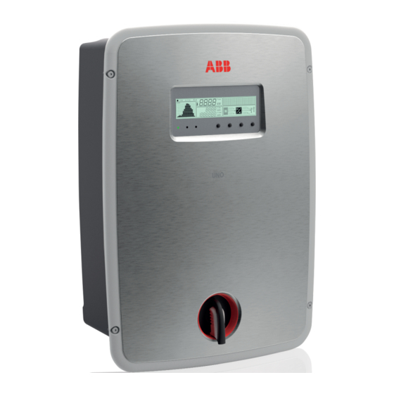
ABB UNO-2.5-I-OUTD Quick Installation Manual
Solar inverters
Hide thumbs
Also See for UNO-2.5-I-OUTD:
- Product manual (101 pages) ,
- Quick installation manual (2 pages)
Advertisement
Quick Links
ABB Solar inverters
Quick Installation Guide
UNO-2.0/2.5-I-OUTD
EN
In addition to what is explained below, the safety and installation information provided in the
installation manual must be read and followed. The technical documentation and the interface
and management software for the product are available at the website.
The device must be used in the manner described in the manual. If this is not the case the
safety devices guaranteed by the inverter might be ineffective.
Installation position
- Install on a wall or strong structure suitable for bearing the weight
- Install in safe, easy to reach places
UNO
UNO
UNO
- If possible, install at eye-level so that the display and status LEDs can be seen easily
- Install at a height that considers the heaviness of the equipment
- Install vertically with a maximum inclination of +/- 5°
- To carry out maintenance of the hardware and software of the equipment, remove the covers
UNO
UNO
on the front. Check that there are the correct safety distances for the installation that will allow
the normal control and maintenance operations to be carried out
- Comply with the indicated minimum distances
UNO
UNO
- For a multiple installation, position the inverters side by side
35
cm
- If the space available does not allow this arrangement, position the inverters in a staggered
arrangement as shown in the figure so that heat dissipation is not affected by other inverters
15cm
15cm
UNO
UNO
UNO
Final installation of the inverter must not compromise access to any disconnection
devices that may be located externally.
Please refer to the warranty terms and conditions available on the website and evaluate
50
any possible exclusion due to improper installation.
cm
UNO
UNO
4.
LEDs and BUTTONS, in various combinations, can be used to view the status or carry out complex actions that are described more fully in the manual.
GREEN On if the inverter is
POWER
working correctly. Flashes when
LED
checking the grid or if there is
insufficient sunlight.
YELLOW The inverter has de-
ALARM
tected an anomaly. The anomaly is
LED
shown on the display.
POWER
ALARM
RED Ground fault on the DC side
GFI LED
of the PV generator. The error is
shown on the display.
The operating parameters of the equipment are displayed through the display
Description of symbols and display fields.
b1
RS485 data transmission
b13 Daily energy produced
b14 PV voltage > Vstart
b2
RS485 line present
Radio line present.
b15 DC voltage value
b3
Bluetooth line present (*)
b16 DC current value
b4
WiFi line present (*)
b17 DC/DC circuit part
b5
Warning
b18 DC/AC circuit part
b6
Temperature derating
b19 AC voltage value
b7
b8
Instantaneous power
b20 AC current value
b9
MPP scan running
b21 Connection to the grid
b10 Graphic display
b22 Grid status
b11 Power graph
b23 Cyclic view on/off
b12 Total energy
(*) NOT available
5.
Transport and handling
Transport of the equipment, especially by road, must be carried out with by suitable ways and means for pro-
tecting the components from violent shocks, humidity, vibration, etc.
Lifting
The means used for lifting must be suitable to bear the weight of the equipment.
Unpacking and checking
The components of the packaging must be disposed on in accordance with the regulations in force in the
country of installation.
When you open the package, check that the equipment is undamaged and make sure all the components are
present. If you find any defects or damage, stop unpacking and consult the carrier, and also promptly inform the
Service ABB.
Equipment weight
Model
UNO-2.0-I-OUTD
UNO-2.5-I-OUTD
UNO-2.0-I-OUTD-S
UNO-2.5-I-OUTD-S
35
cm
15cm
15cm
UNO
50
cm
It is used to access the main menu, to go
ESC
back to the previous menu or to go back
to the previous digit to be edited.
It is used to scroll up the menu options or to
UP
shift the numerical scale in ascending order.
DC
AC
It is used to scroll down the menu options
DOWN
or to shift the numerical scale in descending
order.
GFI
ESC
UP
DOWN
ENTER
It can be used to conrm an action, to access
14
12
13
the submenu for the selected option (indica-
ENTER
ted by the > symbol) or to switch to the next
digit to be edited.
: warnings, alarms, channels, voltages, etc.
12
b2
b4
b6
b8
b1
b3
b5
b7
b9
b11
b13
b12
Mass weight
Lifting points n°#
17 Kg
2
1.
The labels on the inverter have the Agency marking, main technical data and identification of the equipment and manufacturer
www.abb.com/solar
SOLAR INVERTER
V
520 V
dc max
V
90 - 520 V
dc MPP
V
200 - 470 V
dc, Full Power
I
12.8 A
dc max
I
15 A
sc max
IP65
-25 to +60 °C
-13 to +140 °F
The labels attached to the equipment must NOT be removed, damaged, dirtied, hidden,etc...
If the service password is requested, the field to be used is the serial number -SN: YYWWSSSSSS-
In the manual and/or in some cases on the equipment, the danger or hazard zones are indicated with signs, labels, symbols or icons.
Always refer to instruction
manual
Protection rating of
IP65
equipment
Positive pole and negative
pole of the input voltage
(DC)
2.
04
07
10
11
08
3.
Environmental checks
- Consult the technical data to check the environmental parameters to be observed
- Installation of the unit in a location exposed to direct sunlight must be avoided as it may cause:
1. power limitation phenomena in the inverter (with a resulting decreased energy production by the system)
2. premature wear of the electrical/electromechanical components
3. premature wear of the mechanical components (gaskets) and of the user interface (display)
- Do not install in small closed rooms where air cannot circulate freely
- To avoid overheating, always make sure the flow of air around the inverter is not blocked
- Do not install in places where gases or flammable substances may be present
- Do not install in rooms where people live or where the prolonged presence of people or animals is expected, because of
the noise (about 50dB(A) at 1 m) that the inverter makes during operation
- Avoid electromagnetic interference that can compromise the correct operation of electronic equipment, with consequent
situations of danger.
Installations above 2000 metres
On account of the rarefaction of the air (at high altitudes), particular conditions may occur:
- Less efficient cooling and therefore a greater likelihood of the device going into derating because of high internal
temperatures
- Reduction in the dielectric resistance of the air that, in the presence of high operating voltages (DC input), can create
electric arcs (discharges) that can reach the point of damaging the inverter
All installations at altitudes of over 2000 metres must be assessed case by case with the ABB Service department.
6.
Components available for all models
UNO
UNO
UNO
UNO
UNO
UNO
UNO
UNO
UNO
UNO
UNO
7.
b23
b17
b10
b19
DC
AC
04
b15
b18
b21
b16
b14
b20
b22
10
11
08
8.
Opening the front cover is assisted by 2 hinges on both the inner sides of
the inverter, and it can be carried out with ease following the procedure
described below:
- Slacken the 4 screws fastening the front cover
- Open the cover by pulling it toward you and then pushing it upwards on
both sides (steps 2 and 3).
- Lock the cover in place by pushing it forwards (steps 4 and 5)
DIN V VDE 0126-1-1
PROTECTIVE CLASS: I
Made in Italy
www.abb.com/solar
MODEL:
UNO-2.5-I-OUTD-X
SOLAR INVERTER
V
230 V 1Ø
V
520 V
acr
dc max
f
50 Hz
V
90 - 520 V
r
dc MPP
P
φ
2500 W @ 45°C amb.
V
200 - 470 V
acr (cos
= 1)
dc, Full Power
I
12.5 A
I
12.5 A
ac max
dc max
I
1 5 A
sc max
IP65
-25 to +60 °C
5minutes
-13 to +140 °F
General warning - Important
safety information
Temperature range
Always use safety clothing
and/or personal safety
devices
The models of inverter to which this guide refers are available in 2 power ratings:
14
2.0 kW / 2.5 kW.
For inverters of equal output power the variant between the various models is the
12
presence or lack thereof, of the DC disconnect switch
13
- Number of input channels: 1
15
- DC disconnect switch
- Input connectors: quick fit connec-
tors (2 pairs)
- Number of input channels: 1
- DC disconnect switch
- Input connectors: quick fit connec-
tors (2 pairs)
01
Main components
01
Bracket
02
Inverter
02
03
Locking screw
03
04
Front cover
05
Main board
05
09
Service cable glands
06
07
DC disconnect switch
06
08
AC cable gland
Quantity
Components available for all models
Connector for connecting the configu-
2
rable relay
Connector for the connection of the
2
communication and control signals
L-key, TORX TX20
1
Female quick fit connectors
2
Guida
TRIO-20.0-27.6-TL
Oltre
sicurezza
a quanto
di seguito
Rapida
di installazi
-OUTD-Quick
Installation
Guide
condizioni
La tecnologia
ed installazione
di garanzia
power-one.com.
si intendono
nel manuale
riportate
è obbligatorio
esposto
leggere
e rispettare
one
IT RevA
probabilmente
che
di questo
gli inverter
più utilizzati
inoltre
deriva
inverter
trifase
se il Cliente
valide
dal perfezionamento
rispetta
di installazione
quanto
di
disponibile
sul sito
l e i n formazioni
• Convertitore
CARATTERISTICH
•
vogliono
realizzare
di potenza
E
di grandi
impianti
Guida
TRIO-20.0-27.6-TL
al mondo
dimensioni
Rapida
nonché
AURORA
dei modelli
a conseguire
i primi
-OUTD-Quick
descritto
nel manuale.
www.
• Unità
condizioni
sul campo
•
Oltre
a quanto
sicurezza
ed installazione
power-one.com.
di conversione
di seguito
senza
DC/AC
esposto
condensatori
elettrolitici
con
di installazi
per aumentare
orientamento
variabile.
ri s ul t ati
PVI-10.0
i migliori
one
Installation
Guide
e 12.5
i n
che
IT RevA
sono
• Scatola
La tecnologia
probabilmente
• Doppia
dell'energia
• Ampio
di questo
sezione
anche
di garanzia
intervallo
di ingresso
si intendono
con
con
nel caso
valide
nel manuale
inoltre
topologia
è obbligatorio
riportate
di ponte
leggere
di installazione
trifase
e rispettare
ulteriormente
l e i n formazioni
la durata
di vita
• Algoritmo
agli
•
raccolta
• Convertitore
che
vogliono
CARATTERISTICH
standard
di cablaggio
di tensione
realizzare
gli inverter
internazionali
di MPPT
rimovibile
deriva
trifase
inverter
di stringhe
più utilizzati
in ingresso
facile
inseguimento
per una
orientate
al mondo
dal perfezionamento
se il Cliente
rispetta
MPP
indipendente,
in direzioni
diverse
quanto
consente
descritto
di
disponibile
nel manuale.
sul sito
www.
e
• Unità
• Possibilità
• Costruzione
prestazione
•
una
•
E
di energia
costante
di potenza
(versioni
senza
impianti
di grandi
e preciso
veloce
per l'inseguimento
-S2F
-S2,
condensatori
dimensioni
nonché
orientamento
installazione
e -S2X)
con
dei modelli
AURORA
i primi
a conseguire
ottimale
PVI-10.0
ri s ul t ati
una
i migliori
raccolta
e 12.5
Male quick fit connectors
dell'energia
• Doppia
sul campo
• Possibilità
•
• Uscita
di gestire
di conversione
da esterno
sezione
ausiliaria
di connessione
per uso
e stabile
con
DC/AC
direttamente
da display
nell'intero
in qualsiasi
topologia
di tensione
condizione
potenza
della
per aumentare
intervallo
elettrolitici
in tempo
variabile.
una migliore
e per
reale
ulteriormente
i n
sono
che
2
V
PHOTOVOLTAI
AURORA
max
DC
®
TRIO
C INVERTER
®
N10606
MODEL:
• Scatola
•
• Ampio
agli
anche
intervallo
di tensione
di cablaggio
DC (24V,
con
nel caso
di stringhe
in ingresso
di sensori
300mA)
di ingresso
esterni
orientate
inseguimento
di ponte
per il
attiva
ambientale
MPP
trifase
monitoraggio
la potenza
e l e regolazioni
in ingresso
di potenza
e di potenza
di vita
la durata
in uscita
e
Full
Power
DC
V
-2 5to+
I
DC,
SC max
max
V
DC
MPP
I
- 800
440
2 x30
V
2 x 25
A
V
- 950
200
V
1000
A
P
(cos
f
φ
ACnom
nom
P
AC nom
V
TRIO-20.0-TL-OUTD-X
V VDE0126-1-1
PROTECTIV
ECLASS:
0
XX-40
in Italy
DIN
I
Made
400
V 3Ø
, 3W+N+PE
• Algoritmo
raccolta
standard
AURORA
•
PHOTOVOLTAI
internazionali
di MPPT
di energia
TRIO
®
e preciso
veloce
(versioni
rimovibile
-S2,
per una
facile
indipendente,
installazione
in direzioni
condizioni
delle
diverse
consente
una
ambientali
ottimale
reattiva
raccolta
0°F
6 0°C
-1 3to+14
In caso
IP65
AC max
I
= 1)
φ
= ±0.9)
(cos
ACnom
50 Hz
45 °Camb
22000
33 A
W @45
0 W@
.
2000
°Camb
.
DC
max
I
• Costruzione
una
SC max
DC,
Full
MPP
V
V
DC
• Possibilità
DC
V
I
max
- 950
C INVERTER
500
Power
1000
200
costante
da esterno
di gestire
prestazione
TRIO-27.6-TL-OUTD-X
MODEL:
V
V
®
e stabile
per uso
PROTECTIV
V VDE0126-1-1
Made
per l'inseguimento
N10606
-S2F
nell'intero
DIN
e -S2X)
della
ECLASS:
TRIO-XX.X-XX-XXXX-XX
Power-One
in Italy
I
in tempo
potenza
Sul manuale
PHOTOVOLTAI
AURORA
®
e/o in
di richiesta
alcuni
della
password
1 0minutes
il campo
di servizio
6 0°C
-1 3to+14
0°F
-2 5to+
• Possibilità
• Uscita
ausiliaria
- 800
IP65
2 x40
2 x 32
di connessione
DC (24V,
ACnom
f
nom
direttamente
di sensori
P
I
A
V
A
V
AC nom
ACnom
AC max
P
V 3Ø
, 3W+N+PE
=± 0.9)
400
da display
(cos
2760
φ
0 W@
W @45
45 A
45 °Camb
= 1)
50 Hz
in qualsiasi
φ
(cos
30000
°Camb
XX-40
0
P/N:PPPPPPPPPPP
la potenza
.
condizione
di tensione
intervallo
02
ambientale
in ingresso
01
X-XXX
e per
reale
una migliore
I
del manuale
Obbligo
IP65
Grado
DC
Power
Full
max
V
DC
V
max
I
DC
MPP
V
DC,
1000
V
C INVERTER
TRIO
- 950
200
®
di consultazione
N10606
sull'apparecchiatura
MODEL:
casi
TRIO-20.0-TL-OUTD-X
, le zone
ECLASS:
PROTECTIV
V VDE0126-1-1
DIN
Made
in Italy
SN (serial
number)
da utilizzare
nell' eti c
300mA)
è ri p ortato
esterni
Serial
03
attiva
per il
monitoraggio
.
01
Modello
02
1 0minutes
Part
Number
dell'inverter
Number
delle
e l e regolazioni
di inverter
condizioni
03
XXXXXXXXX
SN:SSSSSSSSSS
di potenza
e di potenza
in uscita
04
Q1
WK:WW/YY
reattiva
SC max
Polo
vo della
parecchiatura
0°F
6 0°C
-1 3to+14
-2 5to+
positivo
V
A
2 x30
V
- 800
440
A
2 x 25
di protezione
IP65
= ±0.9)
I
f
(cos
AC max
ACnom
P
ACnom
φ
(cos
AC nom
P
V
= 1)
dell'ap-
nom
φ
rezza
2000
0 W@
Pericolo
, 3W+N+PE
V 3Ø
°Camb
XX-40
400
22000
45 °Camb
tante
W @45
50 Hz
generico
PHOTOVOLTAI
I
DC
di pericolo
0
.
informazione
AURORA
V
di sicu-
-
- Impor
o attenzione
C INVERTER
TRIO
vengono
®
®
hetta applicata
N10606
indicate
04
( i n v e rt e r )
superiore
sulla parte
Power-One
Settimana/Anno
ambientali
dell'inverter
di produzione
In caso
(DC)
Sul manuale
tensione
e polo
di richiesta
della
negati-
di ingresso
Intervallo
1 0minutes
gliamento
.
Obbligo
33 A
V
di utilizzare
V
DC
I
max
max
MPP
DC,
I
Full
di temperature
DC
SC max
200
2 x40
- 950
Power
2 x 32
1000
500
- 800
Senza
Tensione
ACnom
P
nom
MODEL:
V
A
V
V
TRIO-27.6-TL-OUTD-X
A
V
AC nom
f
Made
DIN
V VDE0126-1-1
PROTECTIV
con segnaletica,
pericolosa
V 3Ø
400
, 3W+N+PE
XX-40
in Italy
0
I
ECLASS:
etichette,
TRIO-XX.X-XX-XXXX-XX
simboli
o icone.
01
X-XXX
del manuale
Obbligo
e/o in
alcuni
di consultazione
sull'apparecchiatura
casi
password
di servizio
il campo
nali
-2 5to+
mezzi
6 0°C
e/o i
SN (serial
-1 3to+14
di protezione
0°F
perso
-
l' a bbi-
IP65
number)
I
AC max
mento
Punto
P
ACnom
di collegamento
= 1)
45 A
trasformatore
W @45
50 Hz
φ
30000
2760
45 °Camb
0 W@
(cos
(cos
φ
=± 0.9)
01
P/N:PPPPPPPPPPP
di isola
-
.
°Camb
.
Parti
Modello
02
SN:SSSSSSSSSS
calde
03
parecchiatura
IP65
Grado
di protezione
Pericolo
tante
, le zone
generico
di pericolo
o attenzione
da utilizzare
è ri p ortato
nell' eti c
messa
di protezione
hetta applicata
a terra
03
della
02
sulla parte
04
1 0minutes
Tempo
dell'inverter
Rispettivamente
continua
Number
Settimana/Anno
Number
Serial
Part
di inverter
dell'inverter
di produzione
e alternata
XXXXXXXXX
WK:WW/YY
04
corrente
Q1
Polo
(DC)
vo della
positivo
tensione
e polo
negati-
di ingresso
dell'ap-
rezza
Intervallo
di temperature
informazione
di sicu-
- Impor
-
vengono
Tensione
indicate
con segnaletica,
( i n v e rt e r )
superiore
immagazzinata
di scarica
dell'energia
Obbligo
gliamento
nali
e/o i
mezzi
di utilizzare
di protezione
l' a bbi-
mento
Senza
trasformatore
pericolosa
etichette,
simboli
Parti
o icone.
-
perso
Punto
messa
di collegamento
a terra
della
di isola
-
continua
Rispettivamente
calde
di protezione
Tempo
immagazzinata
e alternata
di scarica
corrente
dell'energia
Bracket and screws for lead sealing the
1
AC connector
Standard Version
3 x
10 mm
Ø
09 10
11 05
09 10
11 05
-S Version
14
12
B
A
13
B
09 10
11
09 10
11
15
Main Components
01
01
Bracket
02
02
Inverter
Locking screw
A
03
Front cover
04
B
Main board
05
A
06
Service cable glands
DC disconnect switch
07
03
AC cable gland
08
05
09
AC output screw terminal block
09
DC input connectors
10
06
11
Anticondensation valve
Display
12
Keypad
13
14
LED panel
Heat sink
15
(step 1)
04
UNO-X.X-I-OUTD-Y
DIN V VDE 0126-1-1
PROTECTIVE CLASS: I
Made in Italy
P/N:PPPPPPPPPPP
MODEL:
UNO-2.0-I-OUTD-S
SN:YYWWSSSSSS WK:WWYY
WO:XXXXXXX
V
230 V 1Ø
acr
f
50 Hz
r
SO:SXXXXXXXX Q1
P
φ
2000 W @ 50°C amb.
acr (cos
= 1)
I
10.5 A
ac max
Inverter model
01
Inverter Part Number
02
Inverter Serial Number
03
5minutes
Week/Year of manufacture
04
Hazardous voltage
Hot surfaces
With isolation
Direct and alternating
transformer
currents, respectively
Point of connection for
Time need to discharge
grounding protection
stored energy
5
.
07
UNO-2.0-I-OUTD
UNO-2.0-I-OUTD-S
- Number of input channels: 1
: No
- DC disconnect switch
07
: Yes
07
- Input connectors: quick fit connec-
tors (2 pairs)
UNO-2.5-I-OUTD
UNO-2.5-I-OUTD-S
- Number of input channels: 1
: No
- DC disconnect switch
: Yes
07
07
- Input connectors: quick fit connec-
tors (2 pairs)
09
AC output screw terminal block
DC input connectors
10
Anticondensation valve
11
12
Display
Keypad
13
LED panel
14
15
Heat sink
Quantity
Two-hole gasket for M20 signal cable
2 + 2
glands and cover
Bracket for wall mounting
1
Bolts and screws for wall mounting
3 + 3
Locking screw
03
for fastening of the
1
inverter to the
ABB
XXXXXX
solar
inverters
XXXXXX
XXXXXX
XXXXXX
XXXXXX
XXXXXX
X
X
Quick Installation Guide
1
In addition
The
technical
to what
is explained
documentation
in this
and
the
interface
guide,
the
safety
and
management
installation
and
for the
software
information
product
provided
are
in the
installation
available
at the
website.
manual
read
t be
mus
and
followed.
Wall/Pole mounting
During installation do not place the inverter
02
with the front cover
04
facing towards the
ground.
- Position the bracket
perfectly level on the wall
01
and use it as a drilling template.
08 06
08 06
- Drill the 3 holes required using a drill with 10mm bit.
The holes must be about 70mm deep.
- On bracket
01
there are 5 fastening holes, but only
3 are used depending on the type of installation: on
a pole holes A, on a wall holes B.
- Fix the bracket to the wall with the 3 wall anchors,
10mm in diameter, supplied.
- Hook the inverter to the bracket by inserting the
head of the rear screws in the slots as shown in
07
05
08
06
the figure.
07
05
08
06
- Proceed to anchor the inverter to the bracket by
tightening the locking screw
03
located on the
lower side.
- Unscrew the 4 screws and open the front cover
04
upwards in order to make all the necessary
connections.
The cover is equipped with fixed hinges and
cannot be removed.
- Once the connections have been made proceed
to closing the cover by tightening the 4 screws
on the front to the torque indicated in the spec-
ifications.
- Remove the protective film located on the front.
1
2
3
4
01
02
04
03
5
Advertisement

Related Manuals for ABB UNO-2.5-I-OUTD


Summary of Contents for ABB UNO-2.5-I-OUTD
- Page 1 (discharges) that can reach the point of damaging the inverter All installations at altitudes of over 2000 metres must be assessed case by case with the ABB Service department. Installation position...
- Page 2 30mA J11 - J12 Output varistors ABB declares that the ABB high-frequency isolated inverters, in terms of their construction, do not inject continuous ground fault currents and therefore there is Inverter data memory card housing no requirement that the differential protection installed downstream of the inverter be type B in accordance with IEC 60755 / A 2.