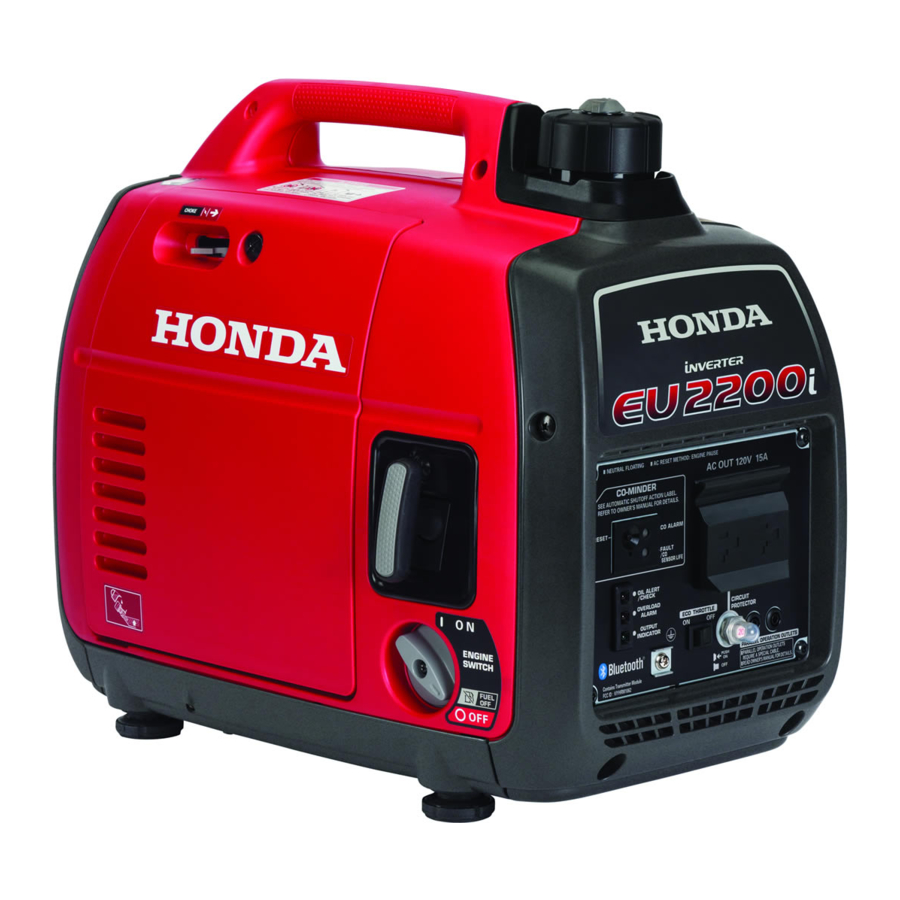
Honda EU2000i Manual
Hide thumbs
Also See for EU2000i:
- Shop manual (102 pages) ,
- Owner's manual (100 pages) ,
- Information (28 pages)
Table of Contents
Advertisement
Quick Links
Advertisement
Table of Contents
Troubleshooting

Summary of Contents for Honda EU2000i
- Page 2 CONTENTS This manual covers service and repair procedures for the SPECIFICATIONS Honda EU2000i generators. A supplement for the EU2000i Companion generator is located in the back of this manual. SERVICE INFORMATION All information contained in this manual is based on the latest product information available at the time of printing.
- Page 4 1. SPECIFICATIONS....... 1-1 4. DIMENSIONAL DRAWINGS....1-4 2. CHARACTERISTICS ......1-2 5. WIRING DIAGRAM ......1-5 3. PERFORMANCE CURVES....1-3...
- Page 5 PWM (Pulse width modulation) * Values indicate the specifications when the Eco-Throttle™ is OFF...
- Page 10 1. SYMBOLS USED IN THIS MANUAL.. 2-1 5. TORQUE VALUES .......2-5 2. SERIAL NUMBER LOCATIONS ..2-1 6. SPECIAL TOOLS.........2-6 3. ELECTRIC PRECAUTIONS....2-2 7. TROUBLESHOOTING ......2-7 4. MAINTENANCE STANDARDS ... 2-3 8. CABLE & HARNESS ROUTING ..2-20...
- Page 21 IGNITION SYSTEM Make a copy of the EU2000i Ignition System Troubleshooting Worksheet (P. 2-13b) and document your test results for future reference or in case you need to call Techline. WARNING Gasoline is highly flammable and explosive. If ignited, gasoline can burn you severely.
- Page 22 If there is no spark at the spark plug, replace the spark plug with a new one and recheck for spark. 10.Disconnect the engine stop switch 2-pin connector and recheck for spark. There should be spark with the switch disconnected. •...
- Page 23 15.Measure the resistance of the exciter winding. ENGINE SIDE 6-PIN CONNECTOR On the engine side of the 6-pin connector, test between the black/blue wire and green wire. Specification: 0.2 ~ 0.3 Document your results and continue. If the exciter winding measures a little over the specification, it may not need to be replaced.
- Page 28 e. GENERATOR • No or low AC output...
- Page 34 1. MAINTENANCE SCHEDULE ..... 3-1 6. VALVE CLEARANCE ......3-5 2. OIL ALERT.......... 3-2 7. FUEL TANK/FUEL FILTER....3-7 3. ENGINE OIL ........3-2 8. FUEL TUBE/FUEL PUMP DIAPHRAGM TUBE ......3-7 4. AIR CLEANER ........3-3 5. SPARK PLUG ........3-4 9. SPARK ARRESTER ......3-8...
- Page 35 Change the oil if it is dirty or contaminated with foreign material. SAE 10W–30 or SAE30 API Service category SJ...
- Page 42 1. MUFFLER..........4-1...
- Page 44 1. AIR CLEANER ........5-1 2. CARBURETOR ........5-2...
- Page 50 1. CONTROL PANEL ......6-1...
- Page 52 Check for continuity between the switch terminals. There must be no continuity with the switch turned ON, and continuity with the switch turned OFF.
- Page 54 1. SIDE COVERS ........7-1 3. FRONT FRAMES/UNDER COVER ..7-3 2. FUEL TANK......... 7-2...
- Page 56 3. FRONT FRAMES/UNDER COVER 6 mm SPECIAL 4.4 N•m (0.4 kg•f, 3.2 lbf•ft)
- Page 60 1. RECOIL STARTER/FAN COVER..8-1 3. EXHAUST MANIFOLD/ 2. FAN SHROUD ........8-5 CARBURETOR INSULATOR ....8-6...
- Page 66 1. GENERATOR ........9-1 2. BREATHER COVER A/B.....9-5...
- Page 72 1. CAM PULLEY ........10-1 5. GOVERNOR........10-14 2. CRANKCASE COVER/ 6. INSPECTION........10-17 CRANKSHAFT/CYLINDER BLOCK.. 10-5 7. VALVE GUIDE REPLACEMENT ..10-24 3. PISTON ..........10-10 8. VALVE SEAT RECONDITIONING ..10-26 4. VALVES ..........10-12...
- Page 100 1. INVERTER TYPE GENERATOR..11-1 3. ECO-THROTTLE 2. FULL TRANSISTOR IGNITION ..11-2 (ELECTRICAL GOVERNOR) ....11-3 1. INVERTER TYPE GENERATOR CONSTRUCTION The Inverter generator has an outer and an inner rotating set of magnets for both the generator and the ignition. The inner set of magnets generate AC in the stator windings, while the outer set generates AC for the ignition coil.
- Page 101 2. FULL TRANSISTOR IGNITION Operating Principles The positive (+) and negative (-) power sources are provided from the exciter winding. AC current is provided to the Ignition coil from the negative (-) power source. Current switching to the ignition coil is controlled by the Field Effect Transistor (FET). The FET turns on when the pulse pole front end reaches the ignition pulse generator and starts to amplify the current in the ignition coil primary winding.
- Page 102 3. ECO-THROTTLE (ELECTRICAL GOVERNOR) Operating Principles • Variable Engine Speed The inverter’s CPU compares the current output voltage, current and engine speed with what is programed it its memory and sets the throttle position accordingly. The actual required engine speed then is based on generator load ratio and temperature.
- Page 108 EU2000i Companion EU2000i...
- Page 110 1. SPECIFICATIONS....... 1-1 3. DIMENSIONAL DRAWINGS....1-4 2. CHARACTERISTICS ......1-2 4. WIRING DIAGRAM ......1-5...
- Page 114 1. CABLE & HARNESS ROUTING..2-1...
- Page 116 1. CONTROL PANEL ......6-1...
- Page 118 NOTES...
- Page 119 NOTES...
- Page 120 NOTES...
- Page 122 This manual has been provided courtesy of My RV Works, Inc. www.myrvworks.com You can find more RV service manuals here: www.myrvworks.com/manuals Over the years of running a mobile RV repair service, having a dedicated place to access service manuals for all the different appliances and components found on RVs was something that I always had a desire to create.


Need help?
Do you have a question about the EU2000i and is the answer not in the manual?
Questions and answers