Fuji Electric PXF4 Instruction Manual
Micro control x
Hide thumbs
Also See for PXF4:
- Instruction manual (24 pages) ,
- Operation manual (80 pages) ,
- Instruction manual (4 pages)
Advertisement
Instruction Manual
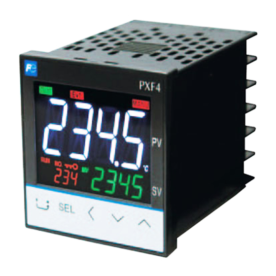
Micro Control X
Model : PXF4
Global Sales Section
Instrumentation & Sensors Planning Dept.
1, Fuji-machi, Hino-city, Tokyo 191-8502, Japan
http://www.fujielectric.com
Phone: +81-42-514-8930 Fax: +81-42-583-8275
http://www.fujielectric.com/products/instruments/
Thank you for purchasing the Fuji module type temperature controller.
instructions.
typographical errors,
absence of information or use of information in this manual.
Before using the product, confirm that it
matches the type ordered.
(For model code, please refer to page 23.)
included.
Temperature Controller
1 unit
Instruction Manual
1 copy
Mounting bracket
1 pc
Waterproof packing
1 pc
Option
Name
Quantity
Order No.
Terminal cover
1 pc
ZZPPXR1-A230
PC loader
1 cable
ZZP*TQ501923C3
communication cable
Shunt resistor
1 pc
ZZPPXR1-A190
Warning
Caution
equipment may be impaired.
In particular, if this product is to be used for applications that require the utmost safety as described
inspections.
INP-TN2PXF4d-E
for details about the items described in this
manual.
Document
Reference No.
Data sheet
EDS11-178
Micro Controller (Model: PXF)
INP-TN5A2400-E
Operation Manual
Micro Controller (Model: PXF)
Communication Functions
INP-TN5A2227-E
Manual (MODBUS)
Ambient temperature
Ambient humidity
Overvoltage category
Pollution degree
Recommended fuse
Usage environment
SSR Drive output terminal, Current output terminal or Communication (RS485) terminal, ensure
requires a clearance at least 1.5 mm and a creepage of at least 3.0 mm. If such insulation is not
1) Over Voltage Category
2) Pollution Degree
3) Required level of Insulating
Failure to observe these instructions violates safety standards. (This product is not a safety equipment.)
................................................................................................................................................
(mains circuit) and this equipment.
Drive output terminal, Current output terminal or Communication (RS485) terminal, ensure to provide a
basic insulation or higher degree of insulation). The basic insulation requires a clearance at least 1.5 mm
compliance may become invalid.
to prevent an electric shock.
or IV.
applied.
................................................................................................................................................
the insulation class for equipment meets usage requirements.
Basic insulation (1500 V AC)
Power supply (100 to 240V AC)
Internal circuit
Process value input
Control output 1 (relay contact)
or
Remote SV input
Motorized valve OPEN output
Control output 1
Control output 2 (relay contact)
(SSR drive, current, voltage)
or
Control output 2
Motorized valve CLOSE output
(SSR drive, current, voltage)
Alarm output 1
Digital input 1 to 3
(relay contact)
Alarm output
1 to 3
(relay contact)
Alarm output 2
Communication (RS-485)
(relay contact)
(1)
(2)
(1): When the 9th code is "J" AL 1 and 2: independent common
(2): When the 9th code is other than "J" AL 1 to 3: shared common
and national standards.
might remain on-state, or off-state. For safety, use a protective circuit outside.
as the equipment to meet your application. Please note that the improper settings may result in
For the details of operation, refer to the separate volume, "Operation Manual (INP-TN5A2400-E)".
Control output 1: heating control
Control output 2 (optional): cooling control
Alarm output 1 to 3 (optional): No function
: Read this instruction manual thoroughly before using the product, and usethe product safely.
errors or failures may be caused.
if the product is used properly.
- 1 -
-10 °C to 50 °C
II
2
Indoor use
II
2
300Vac rms or 300Vdc
About safety standard
Functional insulation (500 V AC)
Power supply (24V DC/24V AC)
Control output 1 (relay contact)
or
Motorized valve OPEN output
CT input
Control output 2 (relay contact)
or
Motorized valve CLOSE output
Alarm output 1
(relay contact)
Alarm output
1 to 3
(relay contact)
Alarm output 2
(relay contact)
(1)
(2)
by IEC 61010-1
No insulation
Internal circuit
Process value input
Remote SV input
CT input
Control output 1
(SSR drive, current, voltage)
Control output 2
(SSR drive, current, voltage)
Digital input 1 to 3
Communication (RS-485)
Advertisement
Table of Contents

Related Manuals for Fuji Electric PXF4


Summary of Contents for Fuji Electric PXF4
- Page 1 Micro Control X Ambient temperature -10 °C to 50 °C Ambient humidity Overvoltage category by IEC 61010-1 Model : PXF4 Pollution degree Recommended fuse Usage environment Indoor use INP-TN2PXF4d-E SSR Drive output terminal, Current output terminal or Communication (RS485) terminal, ensure Global Sales Section requires a clearance at least 1.5 mm and a creepage of at least 3.0 mm.
-
Page 2: Operation
45°C.) is necessary, use a neutral cleaning agent. distributor.) Recommended site conditions rmation of model code About EMC standard Please con rm that the model delivered matches your order. establishment, such as residential areas, or it may cause radio interference. If you use this equipment in domestic locations, take adequate measures on the outside of the equipment to reduce radio interference. -
Page 3: Rear View
73.2 ((If with terminal cover) Mounting frame Waterproof Terminal cover packing (option) Panel * When using the parameter loader with PXF being mounted 7-12 13-18 Terminal screw M3 Rear view Terminal block is not attached to unused terminals (terminal 7 to 12) according to the model. Installing multiple controllers horizontally (In this installing, the waterproof of PXF is lost.) -
Page 4: Standard Type
Standard type Relay output Relay output Control Relay output Relay output Current Voltage Current Voltage output 1 (SPST) (SPDT) (SPST) (SPDT) Control Relay output Relay output Relay output Relay output Relay output None None None None None output 2 (SPST) (SPST) (SPST) (SPST) - Page 5 Motorized valve control type Valve Control Close Valve control Valve Control output 1 Open Alarm output 2 points 1 or 2 points (independent common) Process value input AL1 COM Non-C Universal input AL2 COM (Note 1) Note 1: Power supplies for AL1 and AL2 must be of the same type, either AC or DC.
-
Page 6: Operation Parts
Operation parts Press and hold this key in PV/SV display to start the assigned function. (No function is allocated at the factory.) Press this key once in operation control mode, channel-selection mode, or setup mode to return to PV/SV display. Press this key once in operation mode to move to operation control mode. -
Page 7: Operation Mode
Power ON Operation mode PV/MV display PV/power PV/SV display (Operation screen) Parameter Operation Press control mode and hold AUTO/MANUAL AUTO/MANUAL AUTO/MANUAL AUTO/MANUAL AUTO/MANUAL AUTO/MANUAL Channel Channel selection mode in the selected channel Press and hold Parameter ex) ch1 PID Setup mode Operation mode In this mode the normal operation is performed. - Page 8 then re-start the controller. oFF (auto) / on(manual) This parameter is not displayed in default setting. If you mode need to change this parameter, change the setting of "Ch11 dSP" so that it appears. oFF(RUN) / on(standby) Ramp soak control command Changes ramp soak run states soak).
- Page 9 Sets the SV (set value) 0%FS Note 1) Proportional band 1 (%) Sets the proportional band. 0.1 to 999.9% 5.0% Integration time 1 Sets the integration time. 0 to 3200 sec 240 sec Differential time 1 Sets the differential time. 0.0 to 999.9 sec 60.0 sec ON/OFF control hysteresis 1...
- Page 10 Ramp soak progress Displays the progress of the ramp soak oFF (ramp soak stopped) — 1-rP (ramp in step 1) 1-Sk (soak in step 1) 64rP (ramp in step 64) 64Sk (soak in step 64) MV1(%) Displays the output value of the control output (OUT1) -5.0 to 105.0% —...
- Page 11 PV input type Sets the type of input sensor JPT1: 0.0 to 150.0°C [RESET] JPT2: 0.0 to 300.0°C Refer to section 10 for the detail. JPT3: 0.0 to 500.0°C JPT4: 0.0 to 600.0°C JPT5: -50.0 to 100.0°C JPT6: -100.0 to 200.0°C JPT7: -199.9 to 600.0°C PT1: 0.0 to 150.0°C PT2: 0.0 to 300.0°C...
- Page 12 USER key Assigns the function to the [USER] key 0 to 29 Refer to section 12 for the detail. USER + UP key 0 to 29 USER + DOWN key Assigns the function to the [USER]+ V key 0 to 29 DI-1 function select Allocates a function to DI-1.
- Page 13 Operation timeout (return to PV/SV Sets the time until the display returns to PV/SV screen from 15S: 15 sec display) setting screen. 30S: 30 sec 60S: 60 sec 5M: 5 min 10M: 10 min Blinking SV during Soft Start oFF: OFF oN: ON 0: PV display (no change) 1: PV and alarm status, alternately...
- Page 14 The ramp soak function ( page 15), and SV selection function ( page 17) cannot Caution be combined. Display the system menu (" "). ON/OFF (2-position) 7-1 (page 14) control and SV Can build a control system out of simple elements such as SSR. Display the control parameter ("...
- Page 15 Running auto-tuning Display auto-tuning (" ") and choose the tuning type. suppress the amount of overshoot. Choose the standard type (" ") according to the control target This control introduces an algorithm to prevent the calculated PID result from becoming a Press the key to start auto-tuning.
-
Page 16: Mode Setting
Setting Ending Output OFF Output Repeat Behavior Creating a ramp soak operation pattern Continuous control Continuous control Continuous control Continuous control Continuous control Standby Steps 1 to 8 / Steps 9 to 16 / Steps 17 to 24 / Steps 25 to 32 / Steps 33 to 40 / Steps 41 to 48 / Steps Continuous control Standby Pattern... -
Page 17: Sv Selection Function
2. Error output function 5. SV selection function have been previously decided. Display the palette menu (" ") Display the setup menu (" "). Display SV setting 1 (" ") and set SV1. ") and set the output value. For dual control, set " Press the key to set the value. - Page 18 10. MV limit functions When the user key function code is 27 (SV No.+1, PID No.+1 (send)) and the initial PID Point same as SV No. and minimum MV. and SV No. output value (after limit) PCUT 103% PHC1 PHC2 ").
- Page 19 Set the type and the range for input sensor. Input can be set in the setup menu (" "]. For more on input types, input scaling, decimal point location, and input codes, see "10 Input Range error code is displayed, please eliminate the cause of error immediately. After the cause is eliminated, and Codes (standard range)".
- Page 20 Type A1Tp to A3Tp Alarm Type Action diagram Timer Type A1Tp to A3Tp Alarm Type Action diagram ON delay timer No alarm — dLYn Absolute value alarm High alarm OFF delay timer dLYn ON/OFF delay timer dLYn dLYn Ramp soak delay start Delay start ON Open circuit and short circuit 37 Open loop alarm...
- Page 21 Key function (Current/ Alarm output Indicator (Relay/SSR) Voltage) No function Category Function do1T, do2T, oU1T, oU2T oU1T, oU2T do3T None Control output MV1 (heating) Setting unavailable MV2 (cooling) Starts AT (standard) — Alarm output Alarm 1 — Alarm 2 Setting unavailable —...
- Page 22 You can allocate one of the following functions to each of DI1, DI2, and DI3. These functions are activated by external DI signals. Function Action Criteria No function No action — — — Standby Cancels Standby Edge Manual Auto Edge Remote Edge No function Not for use. — — — Auto tuning (standard) start Runs standard auto-tuning. Start Stop Edge Start Stop Edge Ramp SV ON/OFF Enables or disables ramp SV.
-
Page 23: Specifications
4 5 6 7 8 9 10 11 12 13 <48 x 48mm size> Standard type Digit Specifications Note <Front panel size W × H> 48 × 48mm – <Control output 1> Note1 Relay contact (SPST) Relay contact (SPDT) Note1 SSR drive output Current output Voltage output... -
Page 24: Scope Of Application
10 VA MAX. (100 to 240 V AC), 5 VA MAX. (24 V DC/AC) Control output Relay contact output be charged our call out fee. 1 SPST contact, 250 V AC/30 V DC, 3A (resistive load) 1 SPDT contact, 250 V AC/30 V DC, 5 A (resistive load) our product at repair or replacement of failed parts.
Need help?
Do you have a question about the PXF4 and is the answer not in the manual?
Questions and answers