Table of Contents
Advertisement
Quick Links
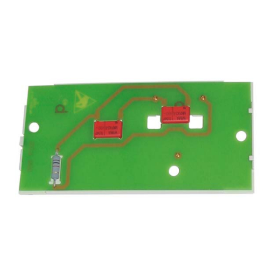
Extra printed circuit board AGU2.522...
for boiler management units LMU74...
Mounting Instructions
The extra printed circuit board (extra PCB) prevents premature failure of the LMU74... caused by loss of
capacitance of a capacitor.
The AGU2.522 ... and this Mounting Instructions are intended for use by OEMs which integrate the extra PCB
in their products!
CC1J7215en
Building Technologies Division
11.05.2011
Industry Sector
Advertisement
Table of Contents

Summary of Contents for Siemens AGU2.522 Series
- Page 1 Extra printed circuit board AGU2.522... for boiler management units LMU74... Mounting Instructions The extra printed circuit board (extra PCB) prevents premature failure of the LMU74... caused by loss of capacitance of a capacitor. The AGU2.522 ... and this Mounting Instructions are intended for use by OEMs which integrate the extra PCB in their products! CC1J7215en Building Technologies Division...
- Page 2 2/21 Building Technologies Division Mounting Instructions AGU2.522... CC1J7215en HVAC Products Contents 11.05.2011...
-
Page 3: Table Of Contents
Contents Typographical conventions................4 Summary ......................5 Target group of users ..................5 Supplementary documentation................ 5 Safety notes..................... 6 Product liability ....................6 Mounting notes ....................6 Standards and certificates ................7 Environmental compatibility................7 Technical data ....................8 Dimensions...................... 9 Step-by-step mounting instructions ............... -
Page 4: Typographical Conventions
The extra PCB may only be used on applications described in the technical documenta- tion and only in connection with components approved or recommended by Siemens. The product can only function correctly and safely if shipped, stored, set up and in- stalled correctly, and operated and maintained as specified. -
Page 5: Summary
Summary The AGU2.522… is an extra PCB used to prevent premature failure of the LMU74... caused by loss of capacitance of a capacitor. Features The extra PCB provides the following basic functions: • Additional capacitors to compensate for potential loss of capacitance of a capacitor •... -
Page 6: Safety Notes
Warning! Do not interfere with or modify the product! Siemens will not assume liability for damage resulting from unauthorized interference! Product liability • All activities (mounting, installation, service work, etc.) must be performed by quali- fied personnel •... -
Page 7: Standards And Certificates
3.3 Standards and certificates Conformity to EEC directives - Electromagnetic compatibility EMC (immunity) 2004/108/EG - Directive for gas-fired appliances 90/396/EWG - Low-voltage directive 2006/95/EG - Immunity EN 61000-6-1 - Emissions EN 61000-6-3 - Electrical safety (chapters 12.2 and 20) EN 60730-1 EN 60730-2-5 ISO 9001: 2010 ISO 14001: 2010... -
Page 8: Technical Data
Technical data General product data Degree of protection IP00 to DIN EN 60529:2000 (IP code) IP40 (to be ensured through mounting inside the boiler) Safety class Parts of safety class 0 Degree of pollution 2 to DIN EN 60730 Packaging Nonreturnable, each package containing a AGU2.522... -
Page 9: Dimensions
Dimensions Dimensions in mm Plastic support AGU2.522... with extra PCB Dimensions in mm Figure 1: Plastic support AGU2.522... with extra PCB 9/21 Building Technologies Division Mounting Instructions AGU2.522... CC1J7215en Industry Sector Dimensions 11.05.2011... - Page 10 Extra PCB Dimensions in mm 7215m03e/0511 Zero point Figure 2: Extra PCB 10/21 Building Technologies Division Mounting Instructions AGU2.522... CC1J7215en Industry Sector Dimensions 11.05.2011...
- Page 11 Extra PCB assembled Dimensions in mm 7215m04e/0511 Solder fillet height max. 1.5 mm The resistor must rest on the extra PCB! Figure 3: Extra PCB assembled 11/21 Building Technologies Division Mounting Instructions AGU2.522... CC1J7215en Industry Sector Dimensions 11.05.2011...
-
Page 12: Step-By-Step Mounting Instructions
Step-by-step mounting instructions Warning! Risk of personal injury or substantial damage to property! Follow the step-by-step mounting instructions. Warning! Protective ESD measure To ensure ESD, wear an ESD wrist strap. Note! Further information Refer to Installation Instructions released by the boiler supplier (e.g. WGB15-38C). Check to ensure the boiler is equipped with an LMU74... - Page 13 Fold down the control section Step 4 Figure 5: Control section folded down Remove cover from the control section Step 5 Figure 6: Cover from control section removed Put on an ESD wrist strap Step 6 Figure 7: ESD wrist strap 13/21 Building Technologies Division Mounting Instructions AGU2.522...
- Page 14 Use a clip to connect the ESD wrist strap to a boiler component with good electrical Step 7 conductance and earth potential Figure 8: Connection of ESD wrist strap to the boiler Put on the ESD wrist strap, ensuring contact with your skin Step 8 Disconnect all cables from the LMU74...
- Page 15 Release the 5 snap-fasteners Step 9 Remove housing from the LMU74... Figure 10: Removal of housing Undo and remove the 7 fixing screws of the LMU74... Step 10 Figure 11: 7 fixing screws 15/21 Building Technologies Division Mounting Instructions AGU2.522... CC1J7215en Industry Sector Step-by-step mounting instructions...
- Page 16 Step 11 Warning! Protective ESD measure and protection against electric shock When removing the motherboard, always hold it by the transformer. Never touch the motherboard itself. Remove motherboard from the housing Figure 12: Removal of motherboard Figure 13: Never touch the motherboard itself! 16/21 Building Technologies Division Mounting Instructions AGU2.522...
- Page 17 Step 12 Warning! Risk of personal injury or substantial damage to property! Keep motherboard in a safe place. Motherboards that fell down must not be used again. Put motherboard on plastic foam suited for ESD or store it in an ESD bag Figure 14: Motherboard placed on plastic foam suited for ESD or stored in an ESD bag 17/21 Building Technologies Division...
- Page 18 Step 13 Warning! Risk of personal injury or substantial damage to property! Do not touch the 3 pins since they can cause injury. Ensure that the 3 pins do not get damaged. Damaged pins will not be detected when checking the boiler’s functions. Consequence: Malfunctions might not be detected for some time.
- Page 19 Step 14 Warning! Risk of personal injury or substantial damage to property! Ensure the extra PCB is correctly fitted (see figure Fitting the extra PCB). Carefully place the extra PCB in the housing of the LMU74…while making certain that the holes are located above the studs. The 3 pins must point upward! Warning! Risk of personal injury or substantial damage to property!
- Page 20 Reassembly: Step 16 Secure the LMU74... with the 7 screws Replace the housing of the LMU74... Housing must audibly click Reestablish and check all cable connections Take off the ESD wrist strap Replace the control section’s cover Fold up the control section Replace the boiler’s front cover Make the safety checks Put the boiler into operation...
-
Page 21: List Of Figures
Figure 15: Package with extra PCB................18 Figure 16: Fitting the extra PCB ..................19 Figure 17: Replacement of LMU74................19 Siemens AG Industry Sector Building Technologies Division © 2011 Siemens AG Industry Sector Building Technologies Division Berliner Ring 23 Subject to change! D-76437 Rastatt Tel.