Table of Contents
Advertisement
Quick Links
Advertisement
Table of Contents

Related Manuals for Motorline professional SLIDE1024


Summary of Contents for Motorline professional SLIDE1024
- Page 1 SLIDE1024 USER'S AND INSTALLER'S MANUAL V4.2 REV. 11/2019...
-
Page 2: Table Of Contents
00. CONTENT 01. SAFETY INSTRUCTIONS INDEX STANDARDS TO FOLLOW 01. SAFETY INSTRUCTIONS This product is certified in accordance with European STANDARDS TO FOLLOW Community (EC) safety standards. 02. AUTOMATISM AUTOMATED SYSTEM TECHNICAL SPECIFICATIONS This product complies with Directive 2011/65/EU of the KIT COMPONENTS European Parliament and of the Council, of 8 June 2011, on 03. - Page 3 01. SAFETY INSTRUCTIONS GENERAL WARNINGS • Children shouldn’t play with the product or opening devices to avoid the motorized door or gate from being triggered involuntarily. • This manual contains very important safety and usage information. very important. Read all instructions carefully before beginning the WARNINGS FOR TECHNICIANS installation/usage procedures and keep this manual in a safe place that it can be consulted whenever necessary.
- Page 4 01. SAFETY INSTRUCTIONS RESPONSABILITY September 2009. • Attach the permanent label for the manual release as close as possible • Supplier disclaims any liability if: to the release mechanism. • Product failure or deformation result from improper installation • Disconnect means, such as a switch or circuit breaker on the electrical use or maintenance! panel, must be provided on the product’s fixed power supply leads in •...
-
Page 5: Automatism
02. AUTOMATISM 02. AUTOMATISM TECHNICAL SPECIFICATIONS KIT COMPONENTS You should check the following items on the automation package before beginning the installation. • Automated system for residential or industrial sliding gates with a maximum of 1000kgs. It consists of a reversing electro-mechanical gearmotor, powered by a 24V control unit. •... -
Page 6: Instalation
03. INSTALLATION INSTALLATION MAP 1 • Engine 12 • Guide 2 • Support column for photocell 13 • Gate 3 • Limit switch plate 14 • Fasteners 4 • Photocell 15 • Battery box 5 • Rack 16 • Transformer 6 •... -
Page 7: Change Engine Orientation
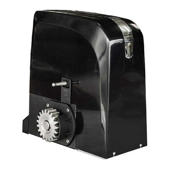
03. INSTALLATION CHANGE ENGINE ORIENTATION CHANGE ENGINE ORIENTATION BATTERIES ORIGINAL ENGINE POSITION If the fastening plate is already tightened on the shoe, it is necessary to • Slide 1024 is shipped from the factory as unscrew it in order to change the orientation of the engine. shown in this image. -
Page 8: Unlock Automatism 7A
03. INSTALLATION 03. INSTALLATION UNLOCK AUTOMATISM SHOE CREATE SHOE • Make a hole with 270x530mm and 250mm depth. Fill with concrete and smooth the top. The engine mounting plate should be applied with the concrete still fresh (see page 8). 250mm TURN KEY EXISTING SHOE... -
Page 9: Engine Installation
03. INSTALLATION ENGINE INSTALLATION *If you are installing the motor on an existing shoe, screw the fastening plate to the floor using suitable screws and bushings (not supplied in the kit). CEMENT MUST BE FRESH Insert the screws and bushings into the four holes of the fixing plate and tighten. With the cement still fresh, apply the fixing plate. -
Page 10: Installing The Metal Rack
03. INSTALLATION INSTALLING THE METAL RACK Put the gate in the open position and unlock the engine (page 7A). Place spacers in all rack holes. You should place them in the center of the ovalized rack holes, so you can fine-tune them at the end of the installation if necessary. Position a rack piece on top of the pinion and level it horizontally with one level. -
Page 11: Nylon Rack Installation
03. INSTALLATION NYLON RACK INSTALLATION Put the gate in the open position and unlo- ck the engine (page 7A). Position a rack piece on top of the pinion, level it horizontally with a level. Begin by securing the rack over the pinion to the gate. Close the gate slightly until another end of the rack rests against the pinion and tightens. -
Page 12: Limit Switch
03. INSTALLATION LIMIT SWITCH OPTION 1 OPTION 2 Position the opening limit switch plate on Position the open limit switch magnet on the rack so that limit switch stops the engine the rack so that it can trigger the engine stop MECHANICAL LIMIT SWITCH END OF MAGNETIC COURSE approximately 10 to 20 mm before the gate... -
Page 13: Component Test
04. COMPONENT TEST 05. MAINTENANCE TESTING ENGINE MAINTENANCE To detect which components are faulty, it is sometimes necessary to perform tests with a direct connec- tion to an external power source (24V ac battery). • Lubricate The diagram below shows how this connection should be made. Lubricate with fine oil, all gate drive systems / shafts.
Need help?
Do you have a question about the SLIDE1024 and is the answer not in the manual?
Questions and answers