Table of Contents
Advertisement
PNEUMERCATOR
Liquid Level Control Systems
Peter Sinkiwskij
Date: 2018.08.03 14:06:26 -04'00'
email=peter@pneumercator.com, c=US
DN: cn=Peter Sinkiwskij, o=Pneumercator Co., Inc., ou=Headquarters,
Digitally signed by Peter Sinkiwskij
© COPYRIGHT 2018 PNEUMERCATOR CO., INC.
TMS4000 Operation Manual 2018-08-03.docx
OPERATION MANUAL
MODEL TMS4000
1785 EXPRESSWAY DRIVE NORTH
HAUPPAUGE, NY 11788
TEL: (631) 293-8450
FAX: (631) 293-8533
http://www.pneumercator.com
MULTI TANK
MONITORING
SYSTEM
DRA WING NO. 20208 REV. A
August 3, 2018
Advertisement
Table of Contents

Related Manuals for Pneumercator TMS4000


Summary of Contents for Pneumercator TMS4000
- Page 1 MULTI TANK Liquid Level Control Systems MONITORING SYSTEM Peter Sinkiwskij Digitally signed by Peter Sinkiwskij DN: cn=Peter Sinkiwskij, o=Pneumercator Co., Inc., ou=Headquarters, email=peter@pneumercator.com, c=US Date: 2018.08.03 14:06:26 -04'00' OPERATION MANUAL DRA WING NO. 20208 REV. A MODEL TMS4000 © COPYRIGHT 2018 PNEUMERCATOR CO., INC.
-
Page 2: Table Of Contents
OPERATION MANUAL TMS4000 Note: A separate INSTALLATION MANUAL is available, but NOT required for TMS4000 operation. TABLE OF CONTENTS Page Section 1 OVERVIEW General System Overview ..................5 1.1.1 Processor Card Connections ..................6 Main Screen ....................... 7 Alarm Acknowledgment ..................... 8 Leak/Point Level Sensor Status ................. - Page 3 OPERATION MANUAL TMS4000 TABLE OF CONTENTS Page Section 3 SYSTEM REPORTS Overview ........................72 Inventory ........................73 Sales ........................75 Product Order ......................77 Delivery ........................79 Water Removal ......................81 Theft ......................... 83 Alarm ........................85 Event ........................87 3.10 Tank Leak/Leak Summary ..................
-
Page 5: General System Overview
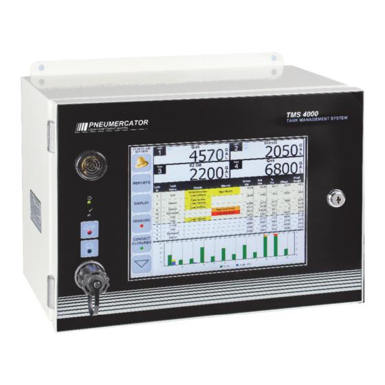
This document covers the operation of the TMS4000 using the touch screen interface. A few additional details are visible on the face of the TMS4000 as shown below. Below the integrated horn in the top left corner are three LEDs. From top to bottom, these are the Green Power LED, Green Normal Status LED, and Red Alarm Status LED. -
Page 6: Processor Card Connections
OPERATION MANUAL TMS4000 1.1.1 PROCESSOR CARD CONNECTIONS TMS4000 Operation Manual 2018-08-03.docx August 3, 2018 PAGE 6... -
Page 7: Main Screen
Single Large Meter with Product and Water Bar Graphs shown The above screens show the Main screen for the TMS4000. The buttons along the left edge provide access to different features that are described on the pages to follow. Above the buttons are shown the current date and time. -
Page 8: Alarm Acknowledgment
Details are provided in a later section. System Acknowledgment: The bell icon shown with SYSTEM below it is used to acknowledge system Events. These include Probe Timeout, Probe Sync, and Sensor Fault Errors. TMS4000 Operation Manual 2018-08-03.docx August 3, 2018 PAGE 8... -
Page 9: Leak/Point Level Sensor Status
Yellow: Sensor fault error. Either open or short-circuited wiring or a faulty sensor. All view: shows the status for all enabled sensors Alarms view: shows only the sensors in an alarm or error state. TMS4000 Operation Manual 2018-08-03.docx August 3, 2018 PAGE 9... - Page 10 Status section and additional information about the physical location of the sensor in the Associations section at the bottom. TMS4000 Operation Manual 2018-08-03.docx August 3, 2018 PAGE 10...
-
Page 11: Cc Input Status
Red: CC Input in an alarm or active state. All view: shows the status for all enabled CC Inputs Alarms view: shows only the CC Inputs in an alarm or error state. TMS4000 Operation Manual 2018-08-03.docx August 3, 2018 PAGE 11... - Page 12 OPERATION MANUAL TMS4000 Additional details for the CC Input are show in the Status section after touching the CC Input Status icon. TMS4000 Operation Manual 2018-08-03.docx August 3, 2018 PAGE 12...
-
Page 13: Printing
TMS4000 1.6 PRINTING Many details may be printed from a TMS4000 equipped with a printer. A print button will be visible wherever printing is available. The information that can be printed includes the Reports and System Configuration. The below screen capture displays the options for the Print button accessible on the Main Screen. -
Page 14: Display Customization
The touch screen may also be recalibrated touching the Touch Cal button (First Generation Resistive LCD Screen Only). Details for recalibrating the screen are outlined in the following section. TMS4000 Operation Manual 2018-08-03.docx August 3, 2018 PAGE 14... - Page 15 Day/Night: The LCD screen has two different color schemes to improve visibility for both Day and Night conditions. This feature can be set to automatically toggle between these two schemes using the information from the Day/Night sensor on the face of the TMS4000 or may be manually toggled by clicking on the Moon/Sun icon.
- Page 16 OPERATION MANUAL TMS4000 Example: One large meter with Product bar graph Example: Four small meters with bar graph disabled TMS4000 Operation Manual 2018-08-03.docx August 3, 2018 PAGE 16...
- Page 17 OPERATION MANUAL TMS4000 Example: Meters Disabled with Product and Water bar graph Example: 2 Small Meters with Product and Temperature bar graph TMS4000 Operation Manual 2018-08-03.docx August 3, 2018 PAGE 17...
- Page 18 Touch the unit displayed on the far right of the meter (in this case, GAL) to display the drop down menu of choices. Touch the radio button for the desired selection to select that choice. TMS4000 Operation Manual 2018-08-03.docx August 3, 2018...
-
Page 19: Touch Screen Calibration (First Generation Resistive Lcd Screen Only)
It is NOT recommended to perform this without contacting Pneumercator Technical Support. Note that you will need a stylus to properly recalibrate the screen. Failure to follow these instructions may result in the screen being unresponsive and require parts be returned to Pneumercator as directed by Pneumercator Technical Support. -
Page 20: Setup Menu
• Firmware: provides the ability to upgrade the firmware or view what the current firmware level is. • Localization: the system language and units of measure are configured here. TMS4000 Operation Manual 2018-08-03.docx August 3, 2018 PAGE 20... -
Page 21: System Configuration
See Section 1.1.1 for location of USB Port. • Save: The current configuration overwrites the previously saved Previous Configuration and the New Configuration changes become the current configuration. TMS4000 Operation Manual 2018-08-03.docx August 3, 2018 PAGE 21... -
Page 22: Header
Line Leak Enable: Makes available the assignment of the Line Leak Channel number of the external LS300 Line Leak console to a specific Tank Channel File Export Prefix: The Prefix is prepended to the file name of the exported report saved to a USB Flash Drive. TMS4000 Operation Manual 2018-08-03.docx August 3, 2018 PAGE 22... -
Page 23: Tanks - General
Touch the +/- buttons to increment Tank Channel by 1. Touch the Tank Channel number to bring up a list of possible Tank Channels. Touch the Tank Channel number on the table to make a selection. TMS4000 Operation Manual 2018-08-03.docx August 3, 2018... - Page 24 Associate with Line Leak Channel: Used in the Line Leak Report to identify the tank that the tested line supports. Only displayed if Line Leak Enable is checked in Header section. TMS4000 Operation Manual 2018-08-03.docx August 3, 2018 PAGE 24...
-
Page 25: Tanks - Dimensions
Custom (3): A horizontal cylinder with curved or dished ends. Custom (8): An asymmetrical tank or other tank with unusual geometry. Contact Pneumercator for assistance. Vertical Conical: A vertical cylinder with a cone bottom. -
Page 26: Tanks - Dimensions - Flat
Rise: Amount of tank tilt present on a horizontal tank. Measured in inches and is never negative. See Probe Location Offset. Radius: 1/2 of the inside diameter. Refer to tank drawing or chart for details. TMS4000 Operation Manual 2018-08-03.docx August 3, 2018 PAGE 26... -
Page 27: Tanks - Dimensions - Vertical
Advanced settings here include the ability to auto select a pump based on the tank with the highest volume. Consult factory for details. Height: The inside height of the tank. TMS4000 Operation Manual 2018-08-03.docx August 3, 2018 PAGE 27... -
Page 28: Tanks - Dimensions - Custom 3
Radius: 1/2 of the tank diameter. Refer to tank drawing or chart for details. Custom Size Datapoints: 3 levels are given based on the radius of the tank. Enter the volumes from the manufacturers tank chart for accurate volume calculations. TMS4000 Operation Manual 2018-08-03.docx August 3, 2018 PAGE 28... -
Page 29: Tanks - Dimensions - Custom 8
Height: The inside height of the tank. Custom Size Datapoints: 8 levels and volumes are required. Refer to the manufacturers tank chart for accurate volume calculations. Contact Pneumercator for additional support in selecting specific data points best suited for the specific tank shape. -
Page 30: Tanks - Dimensions - Vertical Conical
Cone Height: Height of the cone and radius of the tank are used to determine the pitch of the cone. Radius: 1/2 of the diameter of the tank or cone. Refer to tank drawing or chart for details. TMS4000 Operation Manual 2018-08-03.docx August 3, 2018... -
Page 31: Tanks - Dimensions - Virtual
Product Set Points. The tanks in the set are currently defined by assigning a custom tank name containing the Tank Channel numbers of the tanks to be included in the set. TMS4000 Operation Manual 2018-08-03.docx August 3, 2018 PAGE 31... -
Page 32: Tanks - Set Points
The horn symbol to the right of each value can be touched to toggle whether or not the internal horn activates when the alarm threshold is reached. TMS4000 Operation Manual 2018-08-03.docx August 3, 2018 PAGE 32... -
Page 33: Tanks - Probe
Minimum Log Volume: After a transaction is completed, the volume of the transaction is compared to this setting to determine whether to record or discard the transaction. Used to further filter out false transactions. TMS4000 Operation Manual 2018-08-03.docx August 3, 2018 PAGE 33... - Page 34 Probe Location Offset: Used to pinpoint the location of the probe in a tilted tank. Represents how many inches away from the high end of the tank the probe is located. TMS4000 Operation Manual 2018-08-03.docx August 3, 2018 PAGE 34...
-
Page 35: Tanks - Leak Test
TMS4000 2.8 TANKS – LEAK TEST The below screenshots show all of the possible configuration settings for in-tank leak testing. Auto Leak Test Mode settings Scheduled – Relay Test Mode settings TMS4000 Operation Manual 2018-08-03.docx August 3, 2018 PAGE 35... - Page 36 Relay Controls: (Timed Relay Control Mode Only): Select up to 3 relays to activate prior to running a leak test so that a tank in a manifolded set is physically isolated before beginning the leak test. TMS4000 Operation Manual 2018-08-03.docx August 3, 2018...
-
Page 37: Leak Test Scheduling
The In-Tank Leak Test must be enabled as detailed in Section 2.8 above. Failure to do so will result in the below screenshot if any attempt to adjust the schedule is made. TMS4000 Operation Manual 2018-08-03.docx August 3, 2018 PAGE 37... -
Page 38: Leak Test Scheduling - Manual
The test length must be set to comply with local regulations covering the size of tank being tested. Check the box marked “Start Leak Test Schedule On Exit” and touch the Close button to start the test immediately. TMS4000 Operation Manual 2018-08-03.docx August 3, 2018 PAGE 38... -
Page 39: Leak Test Scheduling - Scheduled
Upon completion, the schedule will be satisfied and no further tests will be run until the TMS schedule is reconfigured. This is generally used either to confirm a tank is not leaking on initial install or to manually run a test after a failure to confirm the results. TMS4000 Operation Manual 2018-08-03.docx August 3, 2018 PAGE 39... - Page 40 % Volume, be sure to check the box to establish that requirement. The test will NOT run if the percent volume is below this threshold. The percentage value is configured in the Setup/Config/Tanks/Leak Test menu (See Section 2.8). TMS4000 Operation Manual 2018-08-03.docx August 3, 2018 PAGE 40...
- Page 41 Time, and Test Length. If the test requires a minimum % Volume, be sure to check the box to establish that requirement. The test will NOT run if the percent volume is below this threshold. The percentage value is configured in the Setup/Config/Tanks/Leak Test menu (See Section 2.8). TMS4000 Operation Manual 2018-08-03.docx August 3, 2018 PAGE 41...
- Page 42 Volume, be sure to check the box to establish that requirement. The test will NOT run if the percent volume is below this threshold. The percentage value is configured in the Setup/Config/Tanks/Leak Test menu (See Section 2.8). TMS4000 Operation Manual 2018-08-03.docx August 3, 2018 PAGE 42...
- Page 43 OPERATION MANUAL TMS4000 To stop a test that is running or to stop the scheduler, touch the Suspend button show above. TMS4000 Operation Manual 2018-08-03.docx August 3, 2018 PAGE 43...
-
Page 44: Leak Test Scheduling - Auto
If the test requires a minimum % Volume, be sure to check the box to establish that requirement. The test will NOT run if the percent volume is below this threshold. The percentage value is configured in the Setup/Config/Tanks/Leak Test menu (See Section 2.8). TMS4000 Operation Manual 2018-08-03.docx August 3, 2018 PAGE 44... -
Page 45: Leak Test Scheduling - Scheduled - Relay Control
2.9.4 LEAK TEST SCHEDULING – SCHEDULED – RELAY CONTROL The scheduling options for the Test Mode of Scheduled – Relay Control are identical to those for the Test Mode of Scheduled. See Section 2.9.2 for complete details. TMS4000 Operation Manual 2018-08-03.docx August 3, 2018 PAGE 45... -
Page 46: Cc Inputs
Touch the +/- buttons to increment CC Input by 1. Touch the CC Input number to bring up a list of possible CC Inputs. Touch the CC Input number on the table to make a selection. CC Input Configuration settings. See next page for a description of each setting. TMS4000 Operation Manual 2018-08-03.docx August 3, 2018 PAGE 46... - Page 47 Delay Time: Delay the TMS reaction to the input. Apply To Input Going: Selects whether the TMS response is delayed with the input going active or inactive. TMS4000 Operation Manual 2018-08-03.docx August 3, 2018 PAGE 47...
-
Page 48: Sensor Inputs
Sensor Inputs. The tabs on the left edge show the starting Sensor Input number for the page of choices. Page 1 is shown above and Page 2 is shown below. Touch the Sensor Input number on the table to make a selection. TMS4000 Operation Manual 2018-08-03.docx August 3, 2018 PAGE 48... - Page 49 Mode: Select Leak for sensor detecting leaks. Select Other for sensor used for purposes other than leak detection. The integrated horn beeping pattern will differ for sensors defined as Leak sensors versus Other sensors. Fault Detect: Must be selected for sensors with integrated fault detection circuitry. TMS4000 Operation Manual 2018-08-03.docx August 3, 2018 PAGE 49...
-
Page 50: Relays
Tank Channels. Touch the Tank Channel number on the table to make a selection. Relay assignments for both the Product Set Points and the failure of an In-Tank Leak Test (Leak). TMS4000 Operation Manual 2018-08-03.docx August 3, 2018... - Page 51 OPERATION MANUAL TMS4000 Relay assignments for bottom Water Set Points. Relay assignments for Temperature Set Points. TMS4000 Operation Manual 2018-08-03.docx August 3, 2018 PAGE 51...
-
Page 52: Relays - Cc Inputs
Touch the +/- buttons to increment CC Input by 1. Touch the CC Input number to bring up a list of possible CC Inputs. Touch the CC Input number on the table to make a selection. Relay assignments for the CC Inputs. TMS4000 Operation Manual 2018-08-03.docx August 3, 2018 PAGE 52... -
Page 53: Relays - Sensors
Sensor Inputs. The tabs on the left edge show the starting Sensor Input number for the page of choices. Page 1 is shown above and Page 2 is shown below. Touch the Sensor Input number on the table to make a selection. TMS4000 Operation Manual 2018-08-03.docx August 3, 2018 PAGE 53... - Page 54 OPERATION MANUAL TMS4000 Relay assignments for the Sensor Inputs. TMS4000 Operation Manual 2018-08-03.docx August 3, 2018 PAGE 54...
-
Page 55: Relays - Line Leak Triggers
Touch the +/- buttons to increment Line Leak Channel by 1. Touch the Line Leak Channel number to bring up a list of possible Line Leak Channels. Touch the Line Leak Channel number on the table to make a selection. TMS4000 Operation Manual 2018-08-03.docx August 3, 2018 PAGE 55... -
Page 56: Relays - Site
System Error: Includes Probe Timeout, Probe Sync, and Sensor Fault Error conditions. • Power Failure: A relay will activate once power has been restored to the TMS. • Theft: A theft condition detected for ANY tank will activate a relay output. TMS4000 Operation Manual 2018-08-03.docx August 3, 2018 PAGE 56... -
Page 57: Relays - Relay Mode
Touch the +/- buttons to increment Relay Output Number by 1. Touch the Relay Output Number to bring up a list of possible Relay Output Numbers. Touch the Relay Output Number on the table to make a selection. TMS4000 Operation Manual 2018-08-03.docx August 3, 2018 PAGE 57... - Page 58 Additional Latch Off conditions are configurable on the second page, accessible by touching the down arrow to the right of the plus sign. Complete details can be found on the following page. TMS4000 Operation Manual 2018-08-03.docx August 3, 2018 PAGE 58...
- Page 59 Latch Off condition for the selected relay. • Temperature Set Points: Select the hardware channel of the tank next to the desired Set Point to select the Latch Off condition for the selected relay. TMS4000 Operation Manual 2018-08-03.docx August 3, 2018 PAGE 59...
-
Page 60: Inventory
12:00PM, you would record two snapshots daily: one at midnight and one at noon. This assumes that at least one day of the week is checked. Each snapshot can generate a printout on the TMS if desired by checking the appropriate box. TMS4000 Operation Manual 2018-08-03.docx August 3, 2018 PAGE 60... -
Page 61: Theft
A theft is defined in the TMS as a loss of product during a period when the location is scheduled to be closed. Set the hours of operation above to properly monitor for theft. See Section 2.4 for enabling theft monitoring per tank. TMS4000 Operation Manual 2018-08-03.docx August 3, 2018 PAGE 61... -
Page 62: Dial Out
• Leak: Any Failed In-Tank Leak Test. Not to be confused with Leak Sensors. • Inventory: A daily dialout at the time listed below the checkbox if new Inventory Report exists. TMS4000 Operation Manual 2018-08-03.docx August 3, 2018 PAGE 62... - Page 63 OPERATION MANUAL TMS4000 These represent the configuration settings for each set of dial out rules. TMS4000 Operation Manual 2018-08-03.docx August 3, 2018 PAGE 63...
-
Page 64: Comms (Communications)
TCP Port: The default value of 10001 is recommended unless there are incompatibilities with the current network infrastructure. Security Enable: Requires a 6-digit numeric Access Code that is prepended to any command issued to the TMS. TMS4000 Operation Manual 2018-08-03.docx August 3, 2018 PAGE 64... - Page 65 • Serial C: Supports the 900571-x Communications Expansion Cards • Cell Modem: Intended for a cellular modem. Contact Pneumercator for specific devices supported. Port Speed: determines the maximum speed the modem is permitted to communicate at. Pause length: defines the duration of the pause represented by a comma in the dial out string. See Section 2.15 for entering phone number and comma in configuration.
- Page 66 Security Enable: Requires a 6-digit numeric Access Code that is prepended to any command issued to the TMS. Serial Port A & B are integrated onto the Processor Card of the TMS4000. Serial C & D are optional ports found on select 900571-x communications expansion cards.
-
Page 67: Analog Outputs
Analog Output Channel. The Gain should be left configured as 1.00 unless 0-1 mA mode is required. In that case, the Analog Output Card should be configured for 0-20 mA. Consult Bulletin 139 for complete details. TMS4000 Operation Manual 2018-08-03.docx August 3, 2018 PAGE 67... -
Page 68: Security
TMS4000 2.18 SECURITY The TMS4000 can be configured to restrict access to specific information and/or functions. If this is desired, an Administrator account must first be created that has access to everything including the ability to create and modify additional user accounts with varying degrees of permissions. - Page 69 In-Tank Leak: Failed In-Tank Leak Test o System Errors: Include Probe Timeout, Probe Sync, and Sensor Fault o All Others: Includes Tank Set Points for Product, Water, and Temperature, CC Input and Sensor Alarms. TMS4000 Operation Manual 2018-08-03.docx August 3, 2018 PAGE 69...
-
Page 70: Firmware
The Install button will be available once a flash drive is inserted into the internal USB Port with a valid firmware file supplied by Pneumercator. See Section 1.1.1 for location of USB Port. -
Page 71: Localization
OPERATION MANUAL TMS4000 2.20 LOCALIZATION The localization screen provides a choice between English and Spanish languages and American versus Metric units of measure. TMS4000 Operation Manual 2018-08-03.docx August 3, 2018 PAGE 71... -
Page 72: System Reports
SECTION 3 SYSTEM REPORTS 3.1 OVERVIEW The Reports available in the TMS4000 include the 9 reports displayed above and a System Events Log found in the Setup menu. Any report may be exported to a USB Flash Drive in CSV format by touching the Export button. -
Page 73: Inventory
Ullage: The amount of free space in the tank up to the defined ullage threshold as measured in gallons/liters. See Section 2.3 % Vol: The percentage of total tank volume at the time of the snapshot. TMS4000 Operation Manual 2018-08-03.docx August 3, 2018 PAGE 73... - Page 74 OPERATION MANUAL TMS4000 Provided filter can select a date range and/or specific Tank IDs. Individual columns may be disabled by unchecking box. Grayed out values cannot be disabled. TMS4000 Operation Manual 2018-08-03.docx August 3, 2018 PAGE 74...
-
Page 75: Sales
Net Volume Change: The total change in temperature-compensated volume of liquid in the tank at the beginning of the sale Start Temp: The average liquid temperature at the beginning of the sale End Temp: The average liquid temperature at the end of the sale TMS4000 Operation Manual 2018-08-03.docx August 3, 2018 PAGE 75... - Page 76 OPERATION MANUAL TMS4000 Provided filter can select a date range and/or specific Tank IDs. Individual columns may be disabled by unchecking box. Grayed out values cannot be disabled. TMS4000 Operation Manual 2018-08-03.docx August 3, 2018 PAGE 76...
-
Page 77: Product Order
Total Usage: The total amount of fuel used since the last delivery Daily Usage: The average daily usage Volume Days Left: The estimated number of days of usable fuel remaining based on the Daily Usage. TMS4000 Operation Manual 2018-08-03.docx August 3, 2018 PAGE 77... - Page 78 OPERATION MANUAL TMS4000 Individual columns may be disabled by unchecking box. Grayed out values cannot be disabled. TMS4000 Operation Manual 2018-08-03.docx August 3, 2018 PAGE 78...
-
Page 79: Delivery
Net Volume Change: The total change in temperature-compensated volume of liquid in the tank at the beginning of the delivery Start Temp: The average liquid temperature at the beginning of the delivery End Temp: The average liquid temperature at the end of the delivery TMS4000 Operation Manual 2018-08-03.docx August 3, 2018 PAGE 79... - Page 80 OPERATION MANUAL TMS4000 Provided filter can select a date range and/or specific Tank IDs. Individual columns may be disabled by unchecking box. Grayed out values cannot be disabled. TMS4000 Operation Manual 2018-08-03.docx August 3, 2018 PAGE 80...
-
Page 81: Water Removal
Product % Volume: The percent of total tank volume of all liquid, fuel and water combined, after water was removed Product Ullage: The amount of free space after water was removed in the tank up to the defined ullage threshold as measured in gallons/liters. See Section 2.3 TMS4000 Operation Manual 2018-08-03.docx August 3, 2018 PAGE 81... - Page 82 OPERATION MANUAL TMS4000 Provided filter can select a date range and/or specific Tank IDs. Individual columns may be disabled by unchecking box. Grayed out values cannot be disabled. TMS4000 Operation Manual 2018-08-03.docx August 3, 2018 PAGE 82...
-
Page 83: Theft
Net Volume Change: The total change in temperature-compensated volume of liquid in the tank at the beginning of the theft Start Temp: The average liquid temperature at the beginning of the theft End Temp: The average liquid temperature at the end of the theft TMS4000 Operation Manual 2018-08-03.docx August 3, 2018 PAGE 83... - Page 84 OPERATION MANUAL TMS4000 Provided filter can select a date range and/or specific Tank IDs. Individual columns may be disabled by unchecking box. Grayed out values cannot be disabled. TMS4000 Operation Manual 2018-08-03.docx August 3, 2018 PAGE 84...
-
Page 85: Alarm
Device ID: The ID number of the Device Type in alarm Device Name: The name assigned to the Device Type in alarm Event Condition: The category of alarm Status: Detailed description of the alarm TMS4000 Operation Manual 2018-08-03.docx August 3, 2018 PAGE 85... - Page 86 OPERATION MANUAL TMS4000 Provided filter can select a date range. Individual columns may be disabled by unchecking box. Grayed out values cannot be disabled. TMS4000 Operation Manual 2018-08-03.docx August 3, 2018 PAGE 86...
-
Page 87: Event
Device ID: The ID number of the Device Type causing the event, if applicable Device Name: The name assigned to the Device Type causing the event, if applicable Event Condition: The category of event Status: Detailed description of the event TMS4000 Operation Manual 2018-08-03.docx August 3, 2018 PAGE 87... - Page 88 OPERATION MANUAL TMS4000 Provided filter can select a date range. Individual columns may be disabled by unchecking box. Grayed out values cannot be disabled. TMS4000 Operation Manual 2018-08-03.docx August 3, 2018 PAGE 88...
-
Page 89: Tank Leak/Leak Summary
Slope: The actual average change in volume observed at the completion of the test Result: Pass or Fail Hr: The average cumulative change in volume at the end of each hour. TMS4000 Operation Manual 2018-08-03.docx August 3, 2018 PAGE 89... - Page 90 OPERATION MANUAL TMS4000 Provided filter can select a date range and/or specific Tank IDs. Individual columns may be disabled by unchecking box. Grayed out values cannot be disabled. TMS4000 Operation Manual 2018-08-03.docx August 3, 2018 PAGE 90...
-
Page 91: System Events
3.11 SYSTEM EVENTS Date: Date the incident occurred Time: Time the incident occurred Description: A description of the incident User Name: The name of the user responsible for the security event. TMS4000 Operation Manual 2018-08-03.docx August 3, 2018 PAGE 91... - Page 92 OPERATION MANUAL TMS4000 Provided filter can select a date range. Displays a list of individual columns. This Report does not currently support disabling columns. TMS4000 Operation Manual 2018-08-03.docx August 3, 2018 PAGE 92...
- Page 94 TMS Series Pneumercator, here and after referred to as PCO, warrants its TMS Series family of products to be free of defects in material and workmanship for a period of Twelve (12) months from date of Operation or Fifteen (15) months from date of invoice, whichever comes first.
Need help?
Do you have a question about the TMS4000 and is the answer not in the manual?
Questions and answers