Advertisement
Table of Contents
- 1 Install Batteries
- 2 Link All Devices to Wireless Network
- 3 Exit Wireless Setup
- 4 Advanced Menu Options
- 5 Performing a System Test
- 6 Special Functions
- 7 Key Features
- 8 System Status Information
- 9 Connection Status Information
- 10 Replacing System Components
- 11 Remote Controller
- 12 Wireless Receiver
- 13 Regulatory Information
- Download this manual
Controller Kit Installation Manual
MHK2
Installation guide for:
• Wireless Receiver and Cable
• Remote Controller
DISCONNECT POWER
Can cause electrical shock or equipment damage.
Must be installed by a trained, experienced technician
Read these instructions carefully. Failure to follow these instructions can damage the
product or cause a hazardous condition.
Installation at a glance
Wireless
receiver
Remote
controller
controller
© 2019 Mitsubishi Electric & Electronics USA, Inc.
Suwanee, GA 30024 All Rights Reserved.
The three diamond logo is a registered trademark
of Mitsubishi Electric Corporation
www.mitsubishipro.com
BEFORE BEGINNING INSTALLATION
M32309A
.
.
This document covers linking
and installation procedures for
the Mitsubishi Ducted Systems'
RedLINK™ control devices.
Before you begin, you must attach
the cable to the CN105 connector
on the indoor unit control board,
then follow the steps in this
document.
Remote controllers are
linked to specific indoor
units. Each indoor unit must
have a dedicated remote
controller and wireless
receiver.
33-00446EFS-01
Advertisement
Table of Contents

Related Manuals for Mitsubishi Electric MHK2


Summary of Contents for Mitsubishi Electric MHK2
- Page 1 Each indoor unit must have a dedicated remote controller and wireless receiver. M32309A © 2019 Mitsubishi Electric & Electronics USA, Inc. Suwanee, GA 30024 All Rights Reserved. The three diamond logo is a registered trademark of Mitsubishi Electric Corporation 33-00446EFS-01...
-
Page 2: Install Batteries
See Figure 3. Install batteries Insert AA batteries Mounting MHK2 Controller Align the Wall Plate with the MHK2 Controller and push gently until the MHK2 snaps in place. If needed, gently pull to remove the MHK2 Controller from the Wall Plate. - Page 3 Optional Decorative Cover Plate installation Use the Optional Cover Plate when you need to cover paint gap from the old control. 4. Separate the Junction Box Adapter from the Cover Plate. See Figure 4. 5. Mount the Junction Box Adapter to the wall or an electrical box using any of the eight screw holes.
-
Page 4: Link All Devices To Wireless Network
3. Press DONE to display the home screen. 4. The MHK2 Controller will display a "WAIT" screen while it receives data from the air conditioner. While on the "WAIT" screen: SUCCESS •... -
Page 5: Advanced Menu Options
A/C correctly, MHK2 Controller will change from the "Wait" screen to the "Initial Installer Setup" screen and show START SETUP. View ISU 1. The MHK2 will search for A/C support. If it finds A/C support, the controller will load the ISU option and Arrow buttons... - Page 6 Note: Default settings for Function Codes 1-28 are automatically determined by the HVAC equipment. It may take up to 40 seconds to enter setup, and 30 seconds to exit setup. Function # Name Options Notes Power Failure 1 = Disabled Automatic Recovery 2 = Enabled 3 =Not supported...
- Page 7 ISU # ISU Name ISU Options (defaults in bold) Notes Central Controller 0 = Not installed The control determines the correct setting based on whether the central Present 1 = Installed controller was linked to the system. If the central controller is Installed in the system, then the device will function as a non-programmable device and only single setpoint will be supported.
- Page 8 ISU # ISU Name ISU Options (defaults in bold) Notes Lockout Setpoint 0 = Disabled If user attempts to modify the setpoint, flash Locked segment and revert to 1 = Enabled current setpoint if lockout is enabled. Lockout Vane 0 = Disabled If user attempts to modify the vane direction, flash Locked segment if lockout Direction 1 = Enabled...
-
Page 9: Performing A System Test
Performing a system test You can test the system setup in ADVANCED MENU under SYSTEM TEST option. Press and hold Menu on the controller for 5 seconds to access ADVANCED MENU options. to go to SYSTEM TEST. Touch Touch Select or touch text area. Touch to select system test type. -
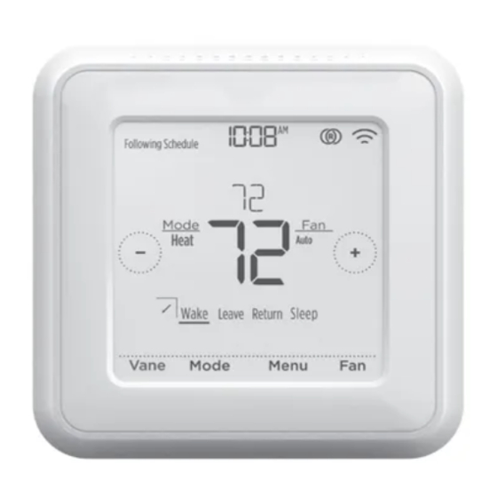
Page 10: Key Features
Key features System status RedLINK wireless Time, ISU #, or information communication status Alert # Cool On, Heat On, Standby. Indicates if the controller is connected to the RedLINK Schedule information interface and communicating Following time-based correctly. temperature control. Connection status Desired Temperature information Displays the current desired... -
Page 11: Replacing System Components
For full list of error codes, please refer to your equipment's technical service manual. Replacing system components NOTE: Only use Mitsubishi Electric components or other designated components for installation. Failure to comply may damage the product or cause a hazardous condition. -
Page 12: Regulatory Information
Accessories & Replacement Parts • Wireless Receiver: 5% to 95% (non-condensing) Item Part Number Remote Controller MRCH2 Receiver and Cable MIFH2 Cable MRC2 © 2019 Mitsubishi Electric & Electronics USA, Inc. Suwanee, GA 30024 All Rights Reserved. 33-00446EFS—01 M.S. 01-19 Printed in U.S.A.