Table of Contents
Advertisement
Operating Instruction
Ident no. 822-073
BAUR Prüf- und Messtechnik GmbH
Raiffeisenstrasse 8, A-6832 Sulz / Austria
Fully Automatic
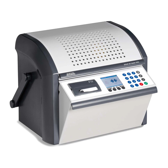
Insulating Oil Tester DPA 75
Designed for the fully automatic measuring of the
electric breakdown strength of insulants
12/98
e-mail: headoffice@baur.at
internet: http://www.baur.at
0-1
Tel +43 / 55 22 / 49 41-0
Fax +43 / 55 22 / 49 4 13
Advertisement
Table of Contents

Related Manuals for Baur DPA 75


Summary of Contents for Baur DPA 75
- Page 1 Operating Instruction Fully Automatic Insulating Oil Tester DPA 75 Designed for the fully automatic measuring of the electric breakdown strength of insulants Ident no. 822-073 12/98 e-mail: headoffice@baur.at BAUR Prüf- und Messtechnik GmbH Tel +43 / 55 22 / 49 41-0 internet: http://www.baur.at...
- Page 3 BAUR. Important unit information! In any case, read carefully! Important information text. Copyright © BAUR Prüf- und Messtechnik GmbH, © Copyright by BAUR A-6832 Sulz / Austria All rights reserved. No part of this publication may be produced,...
- Page 4 This manual contains all information necessary for the correct handling and use of the Fully Automatic Insulating Oil Tester DPA 75. Before using the DPA 75 unit please read carefully this Operating Instruction. If you have any question please contact directly: BAUR Prüf- und Messtechnik GmbH,...
- Page 5 Safety Precautions Please read now and avoid damage and injury later! - The Insulating Oil Tester DPA 75 is built in accordance with today’s state of engineering and is safe to operate. Individual components and the finished unit are inspected continually by our qualified staff within the framework of our Quality Assurance Provisions.
- Page 6 The warranty does not cover damage in transit, batteries, fuses and any readjustments in accordance with the Operating Instruction! We draw attention in addition to the ‘General Terms of Sales and Delivery’ of: BAUR Prüf-und Messtechnik GmbH, A-6832 Sulz / Austria...
-
Page 7: Table Of Contents
Contents Contents 1. Product Information ............... 1-1 1.1 Test cycle ................1-2 1.2 Construction / Principle ............1-3 1.3 Function and control elements ..........1-5 1.4 Control panel ................. 1-7 1.5 Menu overview ..............1-7 1.6 Technical data ............... 1-9 1.7 RBM switching off ............... - Page 8 5. Standard Test .................. 5-1 5.1 Start standard test ..............5-1 5.2 Indication of test results - standard test ......... 5-3 5.3 Printer report (option) - standard test ........5-4 6. Customer-specific Test Cycle ............6-1 6.1 Define and store customer-specific test cycle ....... 6-1 6.2 Start customer-specific test cycle ..........
-
Page 9: Product Information
1. Product Information In all fig. units are shown with options The Insulating Oil Tester DPA 75 The Insulating Oil Tester DPA 75 is used to measure Measuring the electric breakdown strenght of insulating liquids the electric breakdown strength of insulating liquids (eg insulating oil of transformers etc). -
Page 10: Test Cycle
(option). 8 After conclusion of the test cycle close front panel. The DPA unit is switched off automatically. For more and detailled information in operating the DPA 75 unit refer to section 4. Testing Preparations. -
Page 11: Construction / Principle
Product Information 1.2 Construction / Principle Test Vessel and Electrodes Power Supply Control Unit High-voltage Transformer MENU INSTRUMENT SETTING STANDARD SINGLE TEST EXTRA RETURN ENTER Plain Paper Printer RS232 Interface Control Panel (option) bidirectional... - Page 12 Product Information 1 Power supply - Mains operation (100 ... 240 V / 50/60 Hz) possible via mains cable, even if battery is discharged. With mains operation this symbol appears in the upper right corner of any menu: - Battery operation via internal and rechargable battery (2 x 6V / 6.5Ah).
-
Page 13: Function And Control Elements
Product Information 1.3 Function and control elements 6, 7... - Page 14 Product Information 1 Gripping strip for opening/closing the protective hood. 2 Protective hood with self-acting mechanical locking mechanism (double interlock switch - forced contact). For highest operational safety! 3 Test vessel with electrodes - available for all current standards. Quickly removable test vessel for easy cleaning, with a built-in vernier for exact setting of electrode spacing.
-
Page 15: Control Panel
Disabling of the integrated printer is possible - RS232 INFO: Information to the interface configuration RS232 for: - service-mode - cablibration-mode - remote control (with BAUR PC software) - DATE: setting of actual date - TIME: setting of actual time Product Information... - Page 16 Product Information STANDARD MENU - 13 pre-programmed test standards are available: INSTRUMENT SETTING STANDARD ASTM D 1816/84 ASTM D 877/87 SINGLE TEST BS 5874/80 CEI 10-1/73 EXTRA CSSR RVHP/85 IEC 156/95 RETURN ENTER IRAM 2341/72 JIS C2101/78 PN 77/ED4408 SEV 3141/69 UNE 21 309/89 UTE 60 VDE 0370/78...
-
Page 17: Technical Data
Product Information 1.6 Technical data DPA main dimensions Dimensions in mm connection protective earthing T 4 A / fuse 90 . . . 264 V AC / mains supply RS232 bidirectional / 9 pin Sub D DPA interfaces... - Page 18 Product Information Power supply 100 ... 240 V (50 / 60 Hz) Power consumption approx. 120 VA Internal, rechargeable battery (option) 2 x 6 V / 6.5 Ahrs Output voltage, dielectric strength test 0 ... 75 kVrms symmetric For insulating liquids with tan values <...
-
Page 19: Rbm Switching Off
- insulating liquid to be tested does not correspond with the following specifications: insulating liquid with tan values < 4.5 resp. specific resistance > 30 M m Condition for RBM Calibrated DPA 75 unit. Calibration of the DPA 75 unit should be carried out once per year. 1-11... - Page 20 Product Information Notes ○ ○ ○ ○ ○ ○ ○ ○ ○ ○ ○ ○ ○ ○ ○ ○ ○ ○ ○ ○ ○ ○ ○ ○ ○ ○ ○ ○ ○ ○ ○ ○ ○ ○ ○ ○ ○ ○...
-
Page 21: Packing And Delivery
(recorded delivery) for loss assessment and should be made responsible at the same time! We also refer to the ‘General Sales and Delivery Conditions’ of: BAUR Prüf- und Messtechnik GmbH, A-6832 Sulz / Austria... -
Page 22: Check Extent Of Delivery
Packing and Delivery 2.3 Check extent of delivery DPA 75 standard equipment: a Automatic Oil Tester DPA 75 with test report b Test vessel and electrodes c Carrying strap d Mains cable e Operating Instruction - Setting gauge (electrode spacing) - Page 23 Packing and Delivery Test vessels and electrodes IEC 156 Fig I 415-567 Test vessel 0.4 lt. with lid IEC 156 Fig II 415-566 Test vessel 0.4 lt. with lid ASTM D 877 415-568 Test vessel 0.4 lt. with lid ASTM D 1816 Test vessel 0.4 lt.
-
Page 24: Installation
Packing and Delivery 2.4 Installation Lift DPA unit by its carrying handle and put down on desired location. Locate in a suitable place: - Install DPA unit in a dust-free environment. - Do not install DPA unit near laser printer or copier (ozone!). -
Page 25: Putting Into Operation
2 Switch on DPA unit Fold out front panel. DPA unit is switched on. 3 DPA self test DIELTEST DPA 75 After switching on the DPA the unit carries out a self test automatically. Proceeding at error message: SELF TEST - switch on and off again DPA unit - note error message no. -
Page 26: Selecting Language
Putting into Operation 3.1 Selecting language 1 Select menu. SINGLE TEST 2.5 mm 2.0 kV/s MENU START 2 Select menu INSTRUMENT SETTING. MENU INSTRUMENT SETTING STANDARD 3 Confirm black highlighted menu item INSTRUMENT SINGLE TEST SETTING. EXTRA RETURN ENTER On the display the menu INSTRUMENT SETTING INSTRUMENT SETTING appears. -
Page 27: Adjust Contrast Of Display
Putting into Operation On the display the menu LANGUAGES appears. LANGUAGES DEUTSCH ENGLISH 6 Select desired language in the menu LANGUAGES. FRANCAIS ESPANOL 7 Confirm selected language. RETURN ENTER All texts appear in the language defined within this menu. The language is: - factory-set. -
Page 28: Set Actual Date
Putting into Operation 3.3 Set actual date Select menu item DATE within menu INSTRUMENT INSTRUMENT SETTING SETTING. PRINTER RS 232 INFO DATE Confirm black highlighted menu item DATE. TIME RETURN ENTER Select year, month, day one after the other and confirm DATE with key ENTER. -
Page 29: Set Actual Time
Putting into Operation 3.4 Set actual time 1 Select menu item TIME within menu INSTRUMENT INSTRUMENT SETTING SETTING. PRINTER RS 232 INFO DATE 2 Confirm black highlighted menu item TIME. TIME RETURN ENTER Select hours, minutes one after the other and confirm TIME with key ENTER. -
Page 30: Cleaning Of Electrodes
Putting into Operation 3.5 Cleaning of electrodes 1 Select menu item ELECTRODES CLEANING within EXTRA menu EXTRA. BATTERY REPORT NR. ELECTRODES CLEANING 2 Confirm black highlighted menu item ELECTRODES DPA TEST CLEANING. RETURN ENTER 3 Start cleaning of electrodes. ELECTRODES CLEANING START CLEANING BREAKDOWNS ! -
Page 31: Testing Preparations
Testing Preparations 4. Testing Preparations 4.1 Checking battery state of charge 1 Select menu item EXTRA. MENU INSTRUMENT SETTING STANDARD 2 Confirm black highlighted menu item EXTRA. SINGLE TEST EXTRA RETURN ENTER Menu EXTRA appears on the display. EXTRA BATTERY REPORT NR. -
Page 32: Switching Printer On/Off
Testing Preparations 4.2 Switching printer on/off 1 Select menu item PRINTER within menu INSTRUMENT SETTING INSTRUMENT SETTING. CONTRAST LANGUAGES PRINTER 2 Confirm black highlighted menu PRINTER. RS 232 INFO RETURN ENTER 3 Switch printer on/off. PRINTER 4 Confirm installation and back into menu INSTRUMENT SETTING. -
Page 33: Enter Report No
Testing Preparations 4.3 Enter report no. 1 Select menu item REPORT NO. EXTRA within menu EXTRA. BATTERY REPORT NR. ELEKTRODES CLEAN. 2 Confirm black highlighted menu item REPORT NO. DPA TEST RETURN ENTER Select desired numbers for the REPORT NO. one after REPORT NR. -
Page 34: Adjust Electrode Spacing
Testing Preparations 4.4 Adjust electrode spacing 1 Open protective hood. 2 Set scale of vernier to zero. 3 Turn adjusting ring clockwise until the unit sounds a ‘peep’ (electrodes touch each other). 4 Only turn adjusting ring clockwise and slowly step by step to the point the ‘peep’... -
Page 35: Sampling Of Insulating Liquids
Testing Preparations 4.5 Sampling of insulating liquids Meet correct requirements For testing electrical breakdown strength of insulants and as a result their assessment a careful sampling without assimilation of moisture is the deciding factor. Also minor impurities can strongly affect breakdown voltage of the sample. - Page 36 Testing Preparations - Do not touch with bare hands surfaces of sampling Carry out sampling carefully! device getting in contact with insulating liquids. - Let sampled insulating liquid flow into the sample container along its inside wall. Avoid penetration of air.
-
Page 37: Filling Test Vessel
Testing Preparations 4.6 Filling test vessel - The installation site must be dry and free of dust. Before filling Also ref. to section 2.4 Installation, page 22! - Carry out test with insulating liquids in state of delivery without drying or degassing. - Before using test vessel clean it by flushing the vessel with the liquid to be tested (2-3 times). - Page 38 Testing Preparations After filling 6 Insert test vessel into DPA unit. 7 Close protective hood. When not in use: After testing Store test vessel in a clean and dry place filled with insulating liquid and protect it against dust (this avoids formation of moisture in the empty test vessel).
-
Page 39: Carry Out Dpa Test
Testing Preparations 4.7 Carry out DPA test 1 Install and connect calibrator KA75 for high-tension check to the DPA75 unit. Find further information in the separate Operating Instruction KA75. EXTRA BATTERY REPORT NR. ELECTRODES CLEANING DPA TEST RETURN ENTER 2 Select menu item DPA TEST within menu EXTRA. 3 Confirm black highlighted menu item DPA TEST. - Page 40 Testing Preparations Notes ○ ○ ○ ○ ○ ○ ○ ○ ○ ○ ○ ○ ○ ○ ○ ○ ○ ○ ○ ○ ○ ○ ○ ○ ○ ○ ○ ○ ○ ○ ○ ○ ○ ○ ○ ○ ○ ○...
-
Page 41: Standard Test
Standard Test 5. Standard Test 5.1 Start standard test MENU 1 Select menu STANDARD. INSTRUMENT SETTING STANDARD 2 Confirm black highlighted menu item STANDARD. SINGLE TEST EXTRA RETURN ENTER 3 Select desired standard. STANDARD RVHP/85 CSSR 156/95 4 Confirm black highlighted menu item STANDARD IRAM 2341/72 (eg IEC 156/95). - Page 42 Standard Test The test cycle runs fully automatically acc. to STANDARD selected standard. Duration of the test process TEST 1 46.6 kV depends on the selected test standard. PAUSE 01:36 STOP 6 During activated high voltage the red high voltage IEC 156/95 75.0 kV warning lamp lights up.
-
Page 43: Indication Of Test Results - Standard Test
Standard Test 5.2 Indication of test results - standard test After finished test cycle read test data from display. 1 Indication of further test results. IEC 156/95 (eg single results with multiple tests) MEAN VALUE 59.1 kV 13.7 STD. DEV. 23.2 % 21.2 °C TEMP. -
Page 44: Printer Report (Option) - Standard Test
Standard Test 5.3 Printer report (option) - standard test Reading test results from printer report: REPORT DPA 75 V1.0 26.04.94 09:30 test data and evaluation results REPORT NR.: 4309 STANDARD: IEC 156/95 ELECTRODES : .. -
Page 45: Customer-Specific Test Cycle
Customer-spec. Test Cycles 6. Customer-specific Test Cycle 6.1 Define and store customer-specific test cycle Select menu STANDARD. MENU INSTRUMENT SETTING STANDARD Confirm black highlighted menu STANDARD. SINGLE TEST EXTRA RETURN ENTER Select menu item DEFINE TEST CYCLE. STANDARD TEST CYCLE 3 TEST CYCLE 4 Confirm black highlighted menu DEFINE TEST TEST CYCLE 5... - Page 46 Customer-spec. Test Cycles Only carry out LOAD STANDARD (steps 7, 8, 9 and 10) TEST CYCLE 1 if the custumer-specific test cycle should be derived LOAD STANDARD 1.PAUSE from an existing standard. STIRRER 1.PAUSE If a standard is loaded single menu items can be kV/s changed as desired.
- Page 47 Customer-spec. Test Cycles 13 Select desired time period for 1.PAUSE. TEST CYCLE 1 1.PAUSE 14 Confirm input. 0 1 2 3 4 5 6 7 8 9 RETURN ENTER STIRRER 1.PAUSE is the setting time after start of test TEST CYCLE 1 until first switch on of high voltage.
- Page 48 Customer-spec. Test Cycles 21 Select desired value for kV/s. TEST CYCLE 1 1 2 3 5 kV/s 22 Confirm input. RETURN ENTER PAUSE is the break time between the tests, eg break TEST CYCLE 1 between test 1 and 2. PAUSE STIRRER NUMBER OF TESTS...
- Page 49 Customer-spec. Test Cycles 29 Select desired time period for STIRRER. TEST CYCLE 1 STIRRER (min) 30 Confirm input. 2 3 4 5 6 7 8 9 10 CONST RETURN ENTER 31 Select menu item NUMBER OF TESTS. TEST CYCLE 1 PAUSE STIRRER 32 Confirm black highlighted menu item NUMBER OF...
- Page 50 Customer-spec. Test Cycles 37 Select desired value for MAX. OUTPUT VOLT. TEST CYCLE 1 MAX. OUTPUT VOLTAGE 38 Subsequently select OK and confirm input. 75 kV 0 1 2 3 4 5 6 7 8 9 DEL RETURN ENTER WITHSTD. VOLT. is the voltage applied between the TEST CYCLE 1 electrodes during a preset time period (withstand NUMBER OF TESTS...
- Page 51 Customer-spec. Test Cycles The breakdown voltage can be determined after TEST CYCLE 1 expiration of the withstanding voltage: DETERMINE BREAKDOWN VOLTAGE 45 Determine breakdown voltage YES/NO: RETURN ENTER YES The voltage is increased up to breakdown or until switch-off. The voltage is switched off. 46 Confirm input.
-
Page 52: Start Customer-Specific Test Cycle
Customer-spec. Test Cycles 6.2 Start customer-specific test cycle Select menu STANDARD. MENU INSTRUMENT SETTING STANDARD Confirm black highlighted menu item STANDARD. SINGLE TEST EXTRA RETURN ENTER Select defined test cycle, eg TEST CYCLE 1. STANDARD TEST CYCLE 1 TEST CYCLE 2 Confirm black highlighted menu item TEST CYCLE 3 TEST CYCLE 4... -
Page 53: Indication Of Test Results - Customer-Specific Test Cycle
Customer-spec. Test Cycles 6.3 Indication of test results - customer-specific test cycle After finished test cycle read test data from display. Indication of further test results. TEST CYCLE 1 (eg single results with multiple tests) MEAN VALUE 59.1 kV STD. DEV. 13.7 23.2 % TEMP. -
Page 54: Printer Report (Option) - Customer-Specific Test Cycle
Customer-spec. Test Cycles 6.4 Printer report (option) - customer-specific test cycle REPORT DPA 75 V1.2 27.03.95 10:30 REPORT NR.: 4309 STANDARD: TEST CYCLE 1 1.PAUSE : 0 min STIRRER 1.PAUSE : 0 min Reading test results from printer report: kV/s... -
Page 55: Single Test
Single Test 7. Single Test 7.1 Start single test 1 Select menu SINGLE TEST. MENU INSTRUMENT SETTING STANDARD 2 Confirm black highlighted menu item SINGLE TEST. SINGLE TEST EXTRA RETURN ENTER 3 Select desired voltage rate of rise (kV/s). SINGLE TEST (possible input: 0.5 - 1 - 2 - 3 - 5 kV/s) 2.5 mm Check indicated electrode form and adjusted... -
Page 56: Indication Of Test Results - Single Test
After finished test the test data can be read from the display. 2.0 kV/s 21°C MENU START 7.3 Printer report (option) - single test Reading test results from printer report: REPORT DPA 75 V1.0 test data and evaluation results 27.04.94 09:30 REPORT NR.: 4309 STANDARD:... -
Page 57: Maintenance And Care
Repair 8. Maintenance and Care Oil pan Hold oil pan clean and dry! For cleaning it is recommended to use a cloth soaked in petroleum ether! 8.1 Replacing mains fuse 1 Pull out mains cable. 2 Open and swing out fuse holder using a screwdriver. 3 Insert new fuses (T4A/250V). - Page 58 Repair Changing fuses (US ´ EURO) 1 By pressing the clamp pull out the fuse holder plate. 2 Turn fuse holder plate 180 degrees and insert it again. 3 Insert new fuses: US type ø 6.3 x 32 mm Euro Euro type ø...
-
Page 59: Replacing Printer Ribbon (Option)
Repair 8.2 Replacing printer ribbon (option) 1 Remove cover. 2 Press down ribbon on left-hand side and insert the new one. 3 Place on cover and snap it into place. -
Page 60: Replacing Printer Paper Roll (Option)
Repair 8.3 Replacing printer paper roll (option) 1 Remove cover and ribbon. 2 Press snap fasteners on both side simultaneously and pull out printer. 3 Insert new paper roll: Introduce the leading end of the roll into the lower slot - turn transport roll by hand or press right hand key "LF/SEL"... -
Page 61: Spare And Wearing Parts
Glass tube fuse ø 6.3 x 32 / 4 AT 565-513 Ink ribbon for printer (purple) - option 565-514 Paper roll, 2 1/4" (57mm) width, D30, 5m, (option) When ordering spare parts always specify unit type DPA 75 and serial no. acc. to type plate! - Page 62 Spare Parts Test vessels and electrodes IEC 156 Fig I 415-567 Test vessel 0.4l with lid IEC 156 Fig II 415-566 Test vessel 0.4l with lid ASTM D 877 415-568 Test vessel 0.4l with lid ASTM D 1816 Test vessel 0.4l with lid, 415-585 oil stirrer and setting gauges...
- Page 63 Table I 10. Test Standards...
-
Page 64: Test Standards
Test Standards Notes ○ ○ ○ ○ ○ ○ ○ ○ ○ ○ ○ ○ ○ ○ ○ ○ ○ ○ ○ ○ ○ ○ ○ ○ ○ ○ ○ ○ ○ ○ ○ ○ ○ ○ ○ ○ ○ ○... -
Page 65: Index
Index 11. Index Accessories ................2-2 Adjust contrast of display ............3-3 Attention ..................4-4 Carry out DPA test ..............4-9 Changing fuses (US ´ EURO) ............ 8-2 Check extent of delivery ............2-2 Checking battery state of charge ..........4-1 Cleaning of electrodes ............... - Page 66 Index Indication of test results - customer-spec. test ......6-9 Indication of test results - single test .......... 7-2 Indication of test results - standard test ........4-3 Installation ................. 2-4 INSTRUMENT SETTING ............1-7 Interface RS232 ................ 1-4 Interfaces ................... 1-9 kV/s (=voltage rate of rise) ............
- Page 67 Index Safety Precautions ..............0-5 Sampling of insulating liquids ............. 4-5 Selecting language ..............3-2 SINGLE TEST ................1-8 Single Test ................. 7-1 Spare and Wearing Parts ............9-1 STANDARD ................1-8 Standard Test ................5-1 Start customer-specific test cycle ..........6-8 Start single test ................
- Page 68 Index Notes ○ ○ ○ ○ ○ ○ ○ ○ ○ ○ ○ ○ ○ ○ ○ ○ ○ ○ ○ ○ ○ ○ ○ ○ ○ ○ ○ ○ ○ ○ ○ ○ ○ ○ ○ ○ ○ ○ ○...
Need help?
Do you have a question about the DPA 75 and is the answer not in the manual?
Questions and answers
RBM switch off is activated. What would be the remedy.
To remedy the RBM switch off activation on a Baur DPA 75, follow these steps:
1. Identify the cause of the RBM switch off:
- Air breakdowns.
- Insulating liquid is too low-resistive (e.g., contains water).
- Insulating liquid does not meet the required specifications (tan δ values < 4.5 or specific resistance r > 30 MΩm).
2. Address the identified issue:
- Ensure the test environment is free from air breakdowns.
- Check and improve the quality of the insulating liquid as required.
- Use an insulating liquid that meets the specified properties.
3. If RBM switch off occurs, the test cycle will be canceled, and a warning message will appear. Press the "CONT." key to return to the actual menu.
4. Ensure the DPA 75 unit is properly calibrated before testing.
If the issue persists, further troubleshooting or contacting the manufacturer may be necessary.
This answer is automatically generated
RBM switch off has been activated Why does such an error occur? What is the solution?
The RBM switch-off error in the Baur DPA 75 occurs due to the following reasons:
- Air breakdowns.
- The insulating liquid has too low resistivity (e.g., contains water).
- The insulating liquid being tested does not meet the required specifications: tan δ values < 4.5 or specific resistance r > 30 MΩ·m.
To resolve this issue:
- Ensure the insulating liquid meets the required specifications.
- Check for air breakdowns and eliminate any unwanted air gaps.
- Use a properly calibrated DPA 75 unit.
This answer is automatically generated