Table of Contents
Advertisement
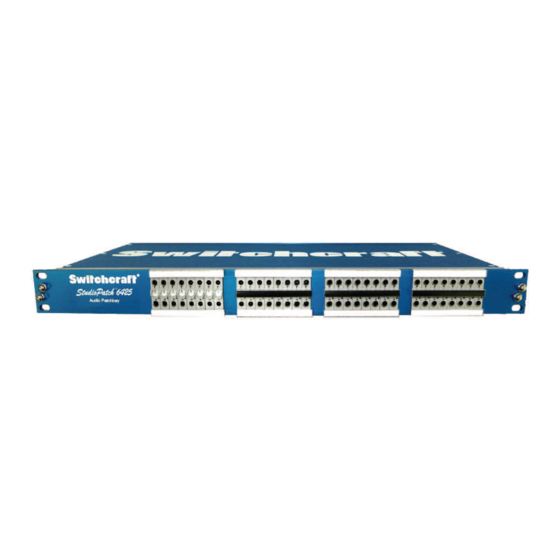
StudioPatch Series
Audio Patchbays
Operation Manual
Thank you for purchasing a StudioPatch Series audio patchbay by Switchcraft
. This product was proudly
®
manufactured in the United States.
The StudioPatch Series (6425 and 9625) are professional TT, 32 and 48 channel audio patchbays that are
capable of handling analog, as well as AES/EBU digital audio signals. They can directly connect to any
piece of audio equipment that uses standard, eight-channel DB25 (also known as DSUB) connectors, such
as TASCAM
DTRS decks, Digidesign
Pro Tools HD systems, Mackie
mixers, line cards, I/O's, and
®
®
®
much more. They can also directly connect to any piece of audio equipment that uses traditional analog
I/O's, such as XLR or TRS, through the use of a wide range of DB25 breakout cable. The connection
possibilities are virtually limitless.
What makes the StudioPatch Series so unique is how they allow you to configure the channels for routing
your audio signals. The normalling of each channel can be set to full, half, or non-normal configurations
from the front of the unit, with the simple twist of a regular screwdriver.
Contained in this manual, are some things you should know about installing, configuring, and caring for
this unit. Should you have any additional questions, please feel free to contact your local Switchcraft
®
dealer / representative, or call us directly at (773) 792-2700, and ask for the customer service department.
Serial Number
Date of Purchase
Place of Purchase
*StudioPatchTM is a trademark of Switchcraft
, Inc.
®
*TASCAM
and DTRS are trademarks of TEAC Corporation.
®
*Pro Tools is a trademark of Digidesign
.
®
*Digidesign
is a division of Avid Technology, Inc.
®
*Mackie
is a trademark of LOUD Technologies Inc.
®
All other trademarks are property of their respective holders.
Specifications subject to change without notice.
Advertisement
Table of Contents

Summary of Contents for Switchcraft StudioPatch Series
- Page 1 I/O’s, such as XLR or TRS, through the use of a wide range of DB25 breakout cable. The connection possibilities are virtually limitless. What makes the StudioPatch Series so unique is how they allow you to configure the channels for routing your audio signals. The normalling of each channel can be set to full, half, or non-normal configurations from the front of the unit, with the simple twist of a regular screwdriver.
-
Page 2: Table Of Contents
Setting The Normals Page 11–13 Designation Strips Page 14 Do's And Don'ts Page 15 Questions And Answers Page 16 Accessories Page 17 DB25 Connector Pinout Diagram Page 18 Cannon DL Connector Pinout Diagram (StudioPatch Series 96DL) Page 19 Warranty Page 20... -
Page 3: What Is A Patchbay And Why Is It Used
At Switchcraft, we realize that the needs of audio engineers can be drastically different depending on their particular situation. Flexibility is critical! INTRODUCING... -
Page 4: Detailed View
StudioPatch 6425 Front View Designation Marking Strips (White) Normalling Screw and clear covers Desginations Strips Removed Rear View Four Female DB25 (Inputs) in USA Four Female DB25 (Outputs) 4-40 Threads Normalling Positions Arrow points at Arrow points at 12:00 position Arrow points at 3:00 position 6:00 position... -
Page 5: Connecting The Studiopatch Series Patchbay
DB25 connector on the unit, the StudioPatch Series can directly link to it. It is important to keep in mind, however, that while most DB25 connectors utilize the standard Tascam DTRS pinout, there are other uses for DB25 cable that have different wiring schemes. - Page 6 DB25 Male to XLR (Also Known as DA-88 to XLR Breakout Cable) DB25 Male to 1/4" (TRS) (Also Known as DA-88 to 1/4˝ TRS Breakout Cable)
-
Page 7: Connection Examples
The rear panels of the StudioPatch Series (6425 and 9625) have a total of either eight or twelve female 25 Pin DB25 (or DSUB) connectors depending on whether you have purchased the 64 or 96 point versions. The top row of connectors are for inputs, and the bottom row are for outputs. Each DSUB can carry eight channels of balanced analog audio, or sixteen channels of AES/EBU standard digital audio. - Page 8 DB25 Breakout Cable As mentioned earlier, another way to connect the StudioPatch Series (6425 and 9625) is with DB25 breakout cable. In this example, your setup would have a DB25 connector on one end (let's say the analog DAW I/O), and XLR's to the destination (the mixing console).
- Page 9 8 Channel DB25 Male to 1/4" (TRS) In example 3, the StudioPatch Series (6425) is connected to a four-channel compressor, and a four-channel microphone preamp. Since these two outboard devices use a total of eight channels, one DB25 to 1/4-inch TRS breakout cable can be used for all of the inputs, and one can be used for all of the outputs.
-
Page 10: Connecting For Digital Audio
Connecting the StudioPatch Series for AES/EBU Digital Audio Signals The StudioPatch Series can also be used for patching AES/EBU digital audio signals. AES/EBU was developed by the Audio Engineering Society and the European Broadcasting Union as a way to transfer digital audio signals between devices. -
Page 11: Setting The Normals
Non-Normalled Position (with grounds bussed) Sleeve Ring Sleeve Ring A non-normal signal path occurs when the screw cam is set in the "N" position (only the tip, ring, and sleeve contacts are utilized). Since there are no normal connections on the jacks, there can be no normal path;... - Page 12 Half Normalled Position (with grounds bussed) Sleeve Ring Sleeve Ring Ring Normal Tip Normal A half-normal position occurs when the screw cam is set in the "H" position. Both tip and ring connections of the source jack (top) are wired respectively to the tip normal and ring normal connections of the destination jack (bottom).
- Page 13 Full Normalled Position (with grounds bussed) Sleeve Ring Ring Normal Tip Normal Sleeve Ring Ring Normal Tip Normal A full-normal position occurs when the screw cam is set in the "F" position. The jack's primary and normalling contacts are fully wired together from top to bottom. This normal signal path can be interrupted and redirected by plugging a patch cord into either jack.
-
Page 14: Designation Strips
Designation Strips Provided with your StudioPatch Series patchbay, are multiple designation strips and clear plastic designation windows. There are eight white, two-sided strips, and four that are black on one side, and white on the other. The all white strips are for labeling the source and destination jacks. The black and white strips are either for labeling the center row (white side) or covering the screw cams from being visible (black side). -
Page 15: Do's And Don'ts
Do's and Don'ts It is very important that your StudioPatch Series patchbay is well cared for. Listed below are a few things to remember: • Do not use a jack in the half-normalled position with a digital (AES/EBU) audio signal and insert a plug into the source (top) jack (see AES/EBU section). -
Page 16: Questions And Answers
Make sure that any cables going to and coming from the StudioPatch are reaching their desired inputs and/or outputs. Question: If I engage phantom power on my mixing console, will it pass through StudioPatch Series patchbays? Answer: Yes, it will. -
Page 17: Accessories
Accessories Although there are multiple brands of patchcords available that will work with Studiopatch Series patchbays, it is recommended that only genuine Switchcraft brand patchcords be used. At Switchcraft ® ® we make sure that our products work well together. The jacks we manufacture in our patchbays are designed to correctly fit the plugs we make. -
Page 18: Db25 Connector Pinout Diagram
StudioPatch Series 6425/9625 DB25 Connector Pinout DB25 Wiring Chart Jack Ring Sleeve (Channel) (White) (Black) (Bare) -
Page 19: Cannon Dl Connector Pinout Diagram (Studiopatch Series 96Dl)
StudioPatch 96DL The StudioPatch Series 96DL is a professional TT, 48 channel audio patchbay. It has all of the same features as the StudioPatch 9625. The only difference, however, is that the rear I/O section consists of four Cannon DL style connectors. -
Page 20: Warranty
® File your paperwork and document your serial number to this owner's manual. Register your serial number by filling out and sending the section below to Switchcraft , Inc. ®...
Need help?
Do you have a question about the StudioPatch Series and is the answer not in the manual?
Questions and answers