Table of Contents
Advertisement
Quick Links
ISOCON-6 USERS GUIDE
ISOCON-6
24V AC or DC POWERED ISOLATING SIGNAL CONVERTER
Whilst every effort has been taken to ensure the accuracy of this document, we accept no responsibility for damage, injury, loss or
expense resulting from errors or omissions, and reserve the right of amendment without notice.
This document may not be reproduced in any way without the prior written permission of the company.
ISOCON-6_Users_Guide
Advertisement
Table of Contents

Summary of Contents for IMO ISOCON-6
- Page 1 ISOCON-6 USERS GUIDE ISOCON-6 24V AC or DC POWERED ISOLATING SIGNAL CONVERTER Whilst every effort has been taken to ensure the accuracy of this document, we accept no responsibility for damage, injury, loss or expense resulting from errors or omissions, and reserve the right of amendment without notice.
-
Page 2: Table Of Contents
ISOCON-6 24V AC or DC POWERED ISOLATING SIGNAL CONVERTER ISOCON-6 USERS GUIDE CONTENTS 1. INTRODUCTION 1.1 Hardware Features 1.1.1 Isolation Detail 2. UNPACKING 3. CONNECTIONS 4. CONFIGURING THE ISOCON 4.1.1 Voltage Input: 4.1.2 Current Input 4.1.3 Millivolt (mV) Input 4.1.4 Potentiometer Input 4.1.5 Thermocouple Input... -
Page 3: Introduction
(see DUALCON-6). Note, units with above options are housed in a 17.5mm wide box. 1.1.1 Isolation Details The ISOCON-6 has full 3 port isolation of 1000V between the Input Stage, Output Stage and Power Supply for functional reasons. 2. UNPACKING: The instrument should be carefully inspected for signs of damage which may have occurred in transit. -
Page 4: Connections
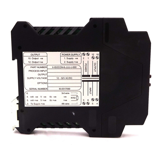
ISOCON-6 24V AC or DC POWERED ISOLATING SIGNAL CONVERTER ISOCON-6 USERS GUIDE 3.CONNECTIONS: The ISOCON is housed in a compact DIN rail mounting enclosure, with 8 terminals, arranged in 4 rows of 2 terminals. Two rows are at the top of the front panel and 2 rows are at the bottom. All the sensor input terminals are on the bottom rows and the power supply and analogue outputs are on the top terminals. -
Page 5: Configuring The Isocon
ISOCON-6 24V AC or DC POWERED ISOLATING SIGNAL CONVERTER ISOCON-6 USERS GUIDE 4. CONFIGURING THE ISOCON: Warning: DO NOT OPEN UNIT OR ADJUST SWITCHES WITH POWER SUPPLY, INPUT OR OUTPUT CONNECTED The ISOCON is an extremely versatile device which can support many different types of input. The unit is configured by turning the power off, selecting the internal switch settings required and turning the power back on. -
Page 6: Voltage Input
ISOCON-6 24V AC or DC POWERED ISOLATING SIGNAL CONVERTER ISOCON-6 USERS GUIDE 4.1.1 Voltage Input: Select the range from the table below and set Switch S1 to the required values. Voltage Switch S1 Range 0-1V 0-2V 0-4V 0-5V 0-7.5V 0-8V... -
Page 7: Current Input
ISOCON-6 24V AC or DC POWERED ISOLATING SIGNAL CONVERTER ISOCON-6 USERS GUIDE 4.1.2 Current Input: Select the range from the table below and set Switch S1 to the required values. Switch S1 Range 0-1mA 0-2mA 0-4mA 0-5mA 0-8mA 0-10mA 0-15mA... -
Page 8: Millivolt (Mv) Input
ISOCON-6 24V AC or DC POWERED ISOLATING SIGNAL CONVERTER ISOCON-6 USERS GUIDE 4.1.3 Millivolt (mV) Input: Select the range from the table below and set Switch S1 to the required values. Switch S1 Range 0-25mV 0-50mV 0-100mV 0-125mV 0-150mV 0-200mV... -
Page 9: Potentiometer Input
ISOCON-6 24V AC or DC POWERED ISOLATING SIGNAL CONVERTER ISOCON-6 USERS GUIDE 4.1.4 Potentiometer Input: Select the range from the table below and set Switch S1 to the required values. Potentiometer Switch S1 Input 2 Wire 0-125R 2 Wire 0-250R... -
Page 10: Thermocouple Input
ISOCON-6 24V AC or DC POWERED ISOLATING SIGNAL CONVERTER ISOCON-6 USERS GUIDE 4.1.5 Thermocouple Input: Select the range from the table below and set Switch S1 to the required values. Switch S1 for Thermocouple Input Temperature Range in °C Switch... -
Page 11: Rtd Input
ISOCON-6 24V AC or DC POWERED ISOLATING SIGNAL CONVERTER ISOCON-6 USERS GUIDE 4.1.6 RTD Input: Select the range from the table below and set Switch S1 to the required values. Switch S1 Range in °C 10 11 0 to 100... -
Page 12: Output Configuration
ISOCON-6 24V AC or DC POWERED ISOLATING SIGNAL CONVERTER ISOCON-6 USERS GUIDE 4.1.7 Output Configuration: Select the range from the table below and set Switch S3 to the required values. Switch S3 mA Source Normal mA Sink Inverted o/p Voltage... -
Page 13: Calibrating The Isocon
ISOCON-6 24V AC or DC POWERED ISOLATING SIGNAL CONVERTER ISOCON-6 USERS GUIDE 5. CALIBRATING THE ISOCON: When the unit is shipped the ISOCON will be calibrated for the input and output types and ranges noted on the side label. If this label is blank then the unit will be calibrated for 4-20mA input and 4-20mA source output. -
Page 14: Installation
ISOCON-6 24V AC or DC POWERED ISOLATING SIGNAL CONVERTER ISOCON-6 USERS GUIDE When the unit is used to convert a thermocouple input it is important when calibrating to ensure that the thermocouple simulator employed is switched to automatic cold junction compensation and is at the same ambient temperature as the ISOCON. Note that this is not always easy to achieve, especially if the ISOCON is mounted in a warm cabinet. -
Page 15: Troubleshooting
ISOCON-6 24V AC or DC POWERED ISOLATING SIGNAL CONVERTER ISOCON-6 USERS GUIDE 7. TROUBLESHOOTING: The ISOCON has some built in self diagnostic functions. If the LED on the front panel is flashing then the fault mode can be found by counting the number of flashes between gaps and using the table below to locate the problem. -
Page 16: Specifications ( @ 25°C)
ISOCON-6 24V AC or DC POWERED ISOLATING SIGNAL CONVERTER ISOCON-6 USERS GUIDE 8. SPECIFICATIONS ( @ 25°C): Insulation Stripping: 12 mm Operating Temperature: 0 to 55 °C Operating Altitude: Sea Level to 2000m Maximum Terminal Torque: 0.4 Nm Humidity: 0-90% RH Weight Approx.
Need help?
Do you have a question about the ISOCON-6 and is the answer not in the manual?
Questions and answers