Table of Contents
Advertisement
Advertisement
Table of Contents

Related Manuals for WABCO OptiTire


Summary of Contents for WABCO OptiTire
- Page 1 OPTITIRE TIRE PRESSURE MONITORING FOR COMMERCIAL VEHICLES SYSTEM DESCRIPTION...
- Page 2 The German version of this document is the original document. Translation of the original document: All non-German language editions of this document are translations of the original document. Edition 2 (08.2019) You will find the current edition at: Document number: 815 010 229 3 (en) http://www.wabco.info/i/533...
-
Page 3: Table Of Contents
Expert’s report / certificates ........................19 5.4.1 ATEX ............................19 5.4.2 Radio approvals ........................19 5.4.3 OptiTire RF declaration of conformity ..................20 Components ..............................21 Sensors ..............................21 6.1.1 The external sensor (WM2) ..................... 22 6.1.2 The internal sensor (WIS) ....................... 27 6.1.3... - Page 4 11.1 Maintenance ............................72 11.2 Replacement and repair ........................72 11.2.1 Replacing an IVTM ECU with an OptiTire ECU ..............72 11.2.2 Replacing 1st generation external sensor with a 2nd generation sensor ........ 72 11.2.3 Wheel change ......................... 72 11.2.4 Replacing PA tubes (external sensor) ..................
-
Page 5: List Of Abbreviations
List of abbreviations List of abbreviations ABBREVIATION MEANING (French: Accord européen relatif au transport international des marchandises Dangereuses par Route); European agreement concerning the international carriage of dangerous goods by road Controller Area Network; asynchronous serial bus system for networking control units in vehicles ECAS Electronically Controlled Air Suspension Electronic Control Unit... -
Page 6: Symbols Used
Reference to information on the internet Descriptive text – Action step 1. Action step 1 (in ascending order) 2. Action step 2 (in ascending order) Ö Consequence of an action Listing „ • Listing Note on the use of a tool / WABCO tool... -
Page 7: Safety Information
Adhere to all instructions, information and safety information to prevent injury to persons and damage to property. WABCO will only guarantee the safety, reliability and performance of their products and systems if all the information in this publication is adhered to. -
Page 8: Introduction
Further studies have shown that over or under inflation of 15% can reduce the life of a tire by more than 10 %. With under-inflated tires there is an increased risk of sustained overheating. This can cause terminal damage to the casing. WABCO OptiTire helps to maintain the correct tire pressure and to detect slow punctures early. Downtimes Tire damage is the most frequent reason for commercial vehicle vehicles to be out of service. - Page 9 „ A deterioration in vehicle handling. „ An extended braking distance. „ WABCO’s OptiTire helps maintain tire pressure at the recommended level, preventing tire damage and enhancing fleet safety. OptiTire cannot announce sudden, extreme tire damage caused by external effects.
-
Page 10: System Description
In the ECU, the measured values are compared to one another and to standard values stored as a parameter set in the ECU. A single OptiTire ECU can monitor up to 20 wheels + 2 spare wheels. Dual tires are measured separately. -
Page 11: Configuration For Bus And Towing Vehicle
In the case of original equipment, the tire pressures are retrieved by a central on-board computer via CAN and displayed on an integrated display in the dashboard. If retrofitted, the WABCO display (WABCO part number: 446 221 000 0) is used for retrieving the tire pressures. - Page 12 System description Example: Parts list for bus / towing vehicle (with external sensors WM2) WABCO PART ARTICULATED NUMBER COMPONENT COMMENT BUS 6X2 446 220 100 0 Communication with trailer ECU / warning lamps 446 220 000 4 Mount Support for mounting the ECU...
- Page 13 960 733 122 0 Fastening strap Fastening strap for 22.5" rims 22.5" Circuit diagrams – Open the WABCO Webshop: https://webshop.wabco-auto.com/webshop/ – Search the desired circuit diagram by entering the 10 digit number: 841 801 970 0 (solobus) „ 841 801 971 0 (articulated bus) „...
-
Page 14: Configuration For Trailers
Configuration for trailers Transmission types To display the OptiTire data of the trailer in the driver’s cabin, both the trailer and towing vehicle must be equipped with OptiTire in combination with the external sensor WM2 if communication is implemented via radio link. - Page 15 If the trailer should be independently equipped with OptiTire, the pressure release can be carried out via telemetry or the vehicles own display. When using the OptiTire display, it requires a special box for splash protection or another protected installation position. The WABCO SmartBoard can be installed as an alternative.
- Page 16 – Search the desired circuit diagram by entering the 10 digit number. If the OptiTire system is installed instead of the IVTM system, additionally use the adapter cable with the WABCO part number: 894 600 001 2 required. Circuit diagram 841 801 943 0 "Trailer ABS VCS"...
- Page 17 Circuit diagram 841 801 913 0 "Trailer EBS D with CAN and SmartBoard" (from year of manufacture 2004) The SmartBoard and OptiTire are connected to the Trailer EBS D modulator on port IN/OUT2. CAN2 must be activated via the Diagnostic Software.
-
Page 18: Optitire In Trailer Operation
Not all towing vehicles display the tire pressures transmitted via CAN in the dashboard. Please contact the manufacturer of the towing vehicle if you have any questions on this subject. Alternatively, the tire pressures of the trailer can be transmitted by a radio signal to an OptiTire system in the towing vehicle. -
Page 19: Expert's Report / Certificates
WABCO GmbH, Am Lindener Hafen 21, 30453 Hanover. 5.4.2 Radio approvals The OptiTire components contain a radio transmitter for the 433 MHz ISM waveband. The output power is less than 1 mW. The following approvals are available: Expert’s report / certificate CE: 2014 / 53 / EU (RED) „... -
Page 20: Optitire Rf Declaration Of Conformity
System description 5.4.3 OptiTire RF declaration of conformity "This device complies with Part 15 of the FCC Rules. Operation is subject to the following two conditions: (1) This device may not cause harmful interference, and (2) This device must accept any interference received, including interference that may cause undesired operation"... -
Page 21: Components
– Search for the desired outline drawing by entering the product number of the component. OptiTire can be interrupted in its function if other devices or systems in the vicinity are also transmitting in the area of 433 MHz. These can be radio sets, radio remote controls (e.g. for door actuation, cranes, forklift), insufficiently shielded electrical drives with high power or other radio transmitters. -
Page 22: The External Sensor (Wm2)
Assignment between wheel and sensor must be absolutely maintained during tire change procedure. If a tire and sensor is incorrectly matched, the OptiTire system will not send the required warning when a wheel with low pressure is wrongly assigned to an axle on which this pressure is actually permissble.. - Page 23 With twin wheels and Super Single rims, problems may occur with the radio transmission due to the immersion depth. To ensure a good quality of reception, T-shaped external sensors should be used (WABCO part numbers: 960 731 031 0 or 960 731 041 0). "External sensors WM2" variants...
- Page 24 Components HOLE, WABCO PART WHEEL APPLICATION NUMBER BOLT BOLT HOLE Ø ANGLE FIGURE Twin tires, Super-Single 960 731 041 0 32 mm 335 mm 70° Towing vehicle: Front axle, 960 731 051 0 26 mm 335 mm 60° load axle...
- Page 25 Components HOLE, WABCO PART WHEEL APPLICATION NUMBER BOLT BOLT HOLE Ø ANGLE FIGURE Towing vehicle: Front axle, 960 731 075 0 26 mm 285.75 mm 33° load axle Twin tires, Super-Single 960 731 081 0 26 mm 225 mm 70°...
- Page 26 The external sensors must be permanently connected to the tires for sensing tire pressures. Use WABCO pre-assembled PA tubes for this purpose. The connection does not have to be disconnected for inflating the tires as valves for inflating the tire are located on the external sensors.
-
Page 27: The Internal Sensor (Wis)
This prevents large forces acting on the internal sensor and tearing it off during tire assembly/disassembly. Using the WABCO OptiTire TPMS Manager (WABCO part number Start-up 300 200 001 0) - Page 28 Make sure you use suitable tire inflation valves during installation of the internal sensor (WIS). Valve sets The following valve sets (consisting of valve, nut and locking screw) are available: APPLICATION WABCO PART NUMBER SURFACE OUTER CONTOUR Standard steel rims 17 to 22.5"...
- Page 29 Components RIM SIZE MATERIAL SUPPLIER RIM NO. VALVE SET 960 732 100 0 / 22.50 x 09.00 Steel Gianetti 15941 960 732 101 0 960 732 100 0 / 22.50 x 09.00 Steel Gianetti 16088 960 732 101 0 960 732 100 0 / 22.50 x 08.25 Steel Gianetti...
-
Page 30: The Internal Sensor (Sms)
Counterweight Not required Installation Installation on the rim by means of fastening strap. Using the WABCO OptiTire TPMS Manager (WABCO part number Start-up 300 200 001 0) Purpose and function In addition to monitoring the tire pressure, the internal sensor also enables an indication of the tire temperature. -
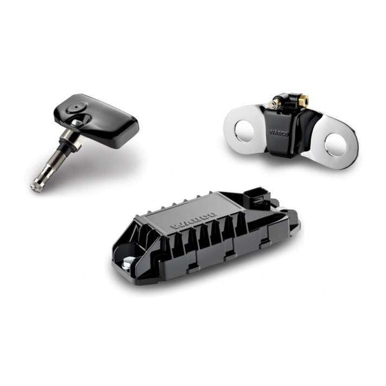
Page 31: Ecu - The Electronic Control Unit
ECU and towing vehicle ECU is ensured. You should use special brackets for good radio contact. Fixing bracket (WABCO part number: 446 220 000 4) Radio contact is provided by antenna integrated in the ECU housing that guarantees interference-free pressure signal reception from all sensors. -
Page 32: Wabco Display
10 "Operation", page 65. Connecting cables OptiTire is connected to the vehicle cabling in two sections on the towing vehicle / bus: The first section comprises the connection of the ECU to the distribution element in the vicinity of „... - Page 33 Stop light / warning lamp 2 yellow Warning lamp 1 green Connection to +12 V/24 V and ignition must be fused with 5 ampere fuses. Since OptiTire has a low current consumption an existing fused circuit can normally be integrated as well.
- Page 34 Components Trailer wiring LEGEND ECU (via adapter cable with WABCO part number: 894 600 001 2) Brown: Ground Red: +12 V/24 V White: Stop light Diagnosis...
- Page 35 Components Cable sets Connecting cables with open end Part Number Cable ends type open 449 376 070 0 7-strand with push-on Bayonet socket contacts and PG screw 7-pin 449 376 250 0 connection 7 x 0.5 mm² for TEBS E (subsystem) Part Number Cable ends type Bayonet socket...
- Page 36 Components for TEBS E (GIO 5) Part Number Cable ends type 449 927 050 0 Socket HDSCS Code B 8-pin 4-pin 449 927 120 0 for electronic extension module and SmartBoard Part Number Cable ends type 2x bayonet socket Code C 449 925 253 0 7-pin 8-pin...
- Page 37 Components Bus cable set, 5-pin Part Number Cable ends type Plug Display + diagnosis 2000 socket with blue 1000 Bayonet socket 894 607 295 0 7-pin 7-pin + open 4-strand 4 x 0.5 mm² Cable set towing vehicle, 7-pin Part Number Cable ends type Plug Display...
- Page 38 For OptiTire it is necessary to switch off the termination via the Expert Mode in the diagnosis. However, this is only necessary if four devices are connected. When using only three devices, the termination remains in OptiTire and the free cable end is sealed with the supplied cap.
-
Page 39: Wabco Tpms Manager
POUND PER QUARTER INCH Celsius bar / °C kPa / °C PSI / °C Fahrenheit bar / °F kPa / °F PSI / °F To control the internal sensor SMS, you may need to update the software version on the WABCO TPMS Manager. - Page 40 Components WABCO TPMS Manager software update 1. Start the WebVT software. 2. Connect the WABCO TPMS Manager to your PC using the supplied USB cable. 3. Click on the My Tools tab. 4. Click Update and select Full. 5. Wait until the update is complete.
-
Page 41: Installation
Installation Installation In this chapter you will learn how the OptiTire is installed your vehicle. Observe all safety instructions when carrying out assembly work on the vehicle. WABCO Bridge configurator – Open the myWABCO website: https://www.am.wabco-auto.com/de/mywabco/welcome/ Help on logging in can be obtained by pressing the Step-by-step instructions button. - Page 42 Installation Assembly of the external sensors WM2 WARNING Risk of accidents due to loosening the fastening screws of the external sensor The safe fixing of the wheel module is only possible when the external sensor housing has a tight fit to the bracket.
- Page 43 3. Mark the position on the tube where the PA tube sits flush with the edge of the external sensor (e.g. using adhesive tape). 4. Cut the PA tube (WABCO part number: 960 731 800 0 bis 960 731 802 0) to the required length if necessary.
- Page 44 Installation – Using the marking, check if the PA tube has been pushed in until the stop. – Pull on the PA tube to check if the PA tube has been inserted with a tight connection (approx. 20 N). – Connect the PA tube to the tire valve. –...
-
Page 45: Assembly Of The Internal Sensor Wis
Installation Valve extension NOTICE Do not use plastic valve extensions. These will not remain tight under permanently existing pressure. Twin wheels (outer wheel) Twin wheels (inner wheel) Assembly of the internal sensor WIS Safety information – Always observe the applicable hazard warnings and correct procedures on the assembly machine. This information has priority over these instructions. - Page 46 Installation Preparing the installation 1. Read chapter "6.1.2 The internal sensor (WIS)", page 27. 2. Jack up the vehicle at the corresponding wheel positions. 3. Remove the wheel. 4. Use a suitable assembly device to remove the tire. It is sufficient to pull the tire over the rime on one side; fee access to the drop-centre and valve is all that is required.
- Page 47 Installation Figure 4 Figure 5 Figure 6 Figure 7 In the case of steel rims the internal sensor sits In the case of aluminium rims only the rear flat on the rim. section of the wheel electronics sits on the rim. Figure 8 Figure 9 Correct fit of the internal sensor...
-
Page 48: Assembly Of The Internal Sensor Sms
Installation Assembly of the internal sensor SMS Safety information – Always observe the applicable hazard warnings and correct procedures on the assembly machine. This information has priority over these instructions. – Replace the internal sensor if the pressure opening is blocked with foreign bodies. –... - Page 49 Installation 2. Guide the fastening strap through the centre of the drop centre and once around the rim (Figure 3). 3. Pass the Velcro through the ladder buckle (Figure 4). 4. Tighten the fastening strap with a tensile force of ~100 Nm and close the Velcro fastener (Figure 5). Note the following: The sensor must lie flat on the drop-centre with the concave underside (Figure 6).
- Page 50 Installation Figure 7 To better locate the sensor when mounted, secure the sensor at the height of the valve (Figure 7). 5. Secure the Velcro fastener by pulling the plastic strap loop centrally onto the sewn end of the fastening strap (Figure 8). Figure 8 ...
-
Page 51: Assembly Of The Tire
Installation Assembly of the tire NOTICE Damage of the internal sensor by fluids The internal sensor can be damaged by the penetration of fluids. – Make sure that the internal sensor does not come into contact with fluids (e.g. assembly fluid). – Do not fill the tires with water. 1. -
Page 52: Mounting The Ecu In Bus / Towing Vehicle
ECU position on vehicle NOTICE Damage to the vehicle frame due to welding Welding work for mounting the bracket (WABCO part number 446 220 000 4) may affect the strength of the vehicle frame. – Screw the bracket to the vehicle. - Page 53 For a good radio connection, the ECU must not be shielded by metal walls in the immediate vicinity, e.g. by a U-beam. – For the towing vehicle use the bracket (WABCO part number 446 220 000 4). Screw the bracket to the vehicle.
-
Page 54: Wiring In Towing Vehicle/Bus
Installation Wiring in towing vehicle/bus Proceed as follows to install the wires of the OptiTire system into the bus or the towing vehicle: – Read Chapter "6.4 Connecting cables", page 32. – Select the suitable circuit diagram (see Chapter "5.2 Configuration for bus and towing vehicle", page 11). -
Page 55: Mounting The Ecu In The Trailer
„ NOTICE Damage to the vehicle frame due to welding Welding work for mounting the bracket (WABCO part number 446 220 000 4) may affect the strength of the vehicle frame. – Screw the bracket to the vehicle. – Attach the ECU below on the frame. - Page 56 Installation Semitrailer: Assembly at cross member Driving direction LEGEND Half distance between two axles Half distance between two sensors Signal radius of a sensor Distance from the centre of the cross member to the centre of the axle Signal range of a sensor Optimum mounting position of the ECU...
-
Page 57: Wiring In Trailer
– Select the suitable circuit diagram (see Chapter "Wiring diagrams for trailers", page 16). – Fit the diagnostic socket to a suitable attachment location and label it with "Diagnostic OptiTire". Locations where diagnostic ports are already located would be specially suitable as the attachment location. -
Page 58: Requirements For Start-Up
You can then use this personal identification number to enable enhanced functions in the software that allow you to modify the settings in electronic control units. WABCO Academy – Registration for a training course / eLearning – Open the myWABCO website: https://www.am.wabco-auto.com/de/mywabco/welcome/... -
Page 59: Diagnostic Hardware
Diagnostic hardware Diagnostic components for towing vehicle The CAN diagnostic cable (WABCO part number 446 300 348 0) is used for diagnosing towing vehicles. Diagnostic components for trailers When carrying out diagnosis on trailers, please extract the WABCO part number of the required... -
Page 60: Start-Up
Start-up Start-up Starting the Diagnostic Software – Start the OptiTire Diagnostic Software. – Switch on ignition. Ensure power supply of trailer if necessary. – Choose whether a guided selection should take place or the Diagnostic Software should automatically search for connected ECUs. -
Page 61: Stimulating The Sensors
– For this purpose, touch the housing of each wheel module below the sticker "OptiTire" for 5 seconds using a magnet (2 kg retention force) or using a bar magnet parallel to the OptiTire logo. External sensor with solenoid for simulating the external sensors... -
Page 62: Warning Lamp Configuration
Change ECU address (Trailer Train) (Trailer ECUs only) For large vehicles and/or a large number of wheels, it is necessary to enable multiple use of OptiTire via a CAN bus. This option cannot be used in conjunction with TEBS or SmartBoard. -
Page 63: Expert Parameters
Start-up 9.2.7 Expert parameters As the last parameter setting define the parameters in the Expert parameters window. Expert parameters are available for special applications: – To do this, activate the Display expert parameters function in the window Parameter under the module configuration tab. -
Page 64: Module Reception
2. Print the start-up log, (Start-up window). 3. Print the vehicle label onto self-adhesive aluminium foil (WABCO part number: 899 200 922 4) (Start-up window). 4. Attach the vehicle label to the vehicle where it is protected and legible. 5. Exit the start-up procedure in the diagnostic software. -
Page 65: Operation
10.2 Switching on of ignition After the ignition is switched on, the OptiTire system runs a self-test to check that all the internal functions are functioning correctly. All symbols are displayed for one second, all pilot lights and audio signals are enabled. This procedure is repeated twice. -
Page 66: Checking Pressure Values
Operation System check The display will change to normal mode if all pressures are correct. Normal mode 10.3 Checking pressure values Proceed as follows to display the pressure values of the individual tires: – Press the button with the tire symbol. The axle of which the pressures are displayed, is marked on the display. -
Page 67: Display Of Faults
10.4 Display of faults When OptiTire detects a fault, an amber or red warning lamp illuminates. Proceed as follows to display the type of fault on the vehicle: – Push button with the question mark after the yellow or red warning lamp lights up. - Page 68 Operation If the system warns about several tires the tire with the most serious fault is indicated first. Repeated pressing of the button with the question mark displays further faults. Creeping pressure loss Overview of fault types ERROR DISPLAY ACTION –...
-
Page 69: Adjusting Tire Pressures
System should be checked in the workshop. No reception Marked wheel has not transmitted pressure value for over one hour. OptiTire has stopped sending warning messages for this wheel, driver needs to check tire pressure on the wheel manually. No reception... - Page 70 Operation System failure A system failure has occurred if display shows crossed-out "IVTM". OptiTire does not signal warning messages for any wheel. The driver must check the tire pressures manually on the wheel. System error Repair note – Check the supply voltage of the ground line.
-
Page 71: Display Via Smartboard
446 192 111 0 / 446 192 211 0 (for hazardous goods vehicles) The SmartBoard is a display and operating console that can be used to display the following information relating to the OptiTire system: System configuration, such as part number, software version, serial number, production date and „... -
Page 72: Workshop Notes
Assembly: If the original IVTM retaining plate and associated 8 mm screws are used, either cap „ nuts or suitable washers must be used in addition to compensate the 11 mm holes in the OptiTire housing. The adapter connector (WABCO part number 894 600 001 2) should be used to connect the „... - Page 73 Workshop notes Please perform wheel changes as follows: 1. Remove any dirt from the external sensor and PA tube. 2. Note ID of external sensor (engraved on top of the housing) and its position on the vehicle, e.g. rear axle left, outside. Alternative: Fix a plate with the description of the location to each external sensor.
-
Page 74: Replacing Pa Tubes (External Sensor)
4. With damaged thread, replace the complete external sensor. 5. Screw the new V203 connection into the thread of the external sensor. A new V203 connection can be obtained using the WABCO part number 893 770 005 2. VOSS SV 203 connection 1. -
Page 75: No Signal Received From The Sensor
A corresponding entry in the diagnostic memory will be seen. Checklist for sensor – If the warning "no reception wheel module" is repeated often in the WABCO Display, you can use the checklist to determine if the sensor should be replaced. - Page 76 DESIGNATION DEFAULT RESULT Activation of the external sensor WM2 with bar magnet or the internal sensors WIS and SMS with the WABCO TPMS Manager (WIS) is not successful. In the display the sensor is indicated with a crossed-out battery symbol.
-
Page 77: Disposal
Disposal Disposal The final and professional decommissioning and disposal of the product must be carried out in „ accordance with the applicable legal regulations of the user country. In particular, the regulations for the disposal of batteries, equipment and the electrical system must be observed. Electrical appliances must be collected separately from household or commercial waste and „... -
Page 78: Wabco Regional Offices
WABCO regional offices WABCO regional offices WABCO Headquarters, Giacomettistrasse 1, 3006 Bern 31, Switzerland, Tel: +32-2663 98 00 WABCO Europe BVBA WABCO Belgium BVBA/SPRL WABCO Austria GesmbH Chaussée de la Hulpe 166 't Hofveld 6 B1-3 Rappachgasse 42 1170 Brüssel 1702 Groot-Bijgaarden Vienna 1110... - Page 79 WABCO regional offices WABCO Australia Pty Ltd WABCO do Brasil Indústria e WABCO Hong Kong Limited Comércio De Freios Ltda Unit 3, 8 Anzed Court 14/F Lee Fund Centre Rodovia Anhanguera, km 106 Mulgrave, Victoria 3170 31 Wong Chuk Hang Road CEP 13180-901...
- Page 80 Notes...
- Page 82 WABCO is also at the forefront commercial vehicle industry, of advanced fleet management true to the motto "Mobilizing systems that contribute to Vehicle Intelligence".
Need help?
Do you have a question about the OptiTire and is the answer not in the manual?
Questions and answers