
Related Manuals for Clarke Strong-Arm CSA50FPB


Summary of Contents for Clarke Strong-Arm CSA50FPB
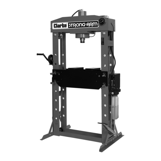
- Page 1 WARNING: Read these instructions before using the press 50 TONNE HYDRAULIC PRESS MODEL NO: CSA50FPB PART NO: 7615203 OPERATION & MAINTENANCE INSTRUCTIONS ORIGINAL INSTRUCTIONS GC0820 - ISS 1...
-
Page 2: Operating Features
INTRODUCTION Thank you for purchasing this CLARKE 50 Tonne Hydraulic Press. Before attempting to operate the press, it is essential that you read this manual thoroughly and carefully follow all instructions given. In doing so you will ensure the safety of yourself and that of others around you, and you can also look forward to the press giving you long and satisfactory service. -
Page 3: Technical Specifications
TECHNICAL SPECIFICATIONS Rated Load 50 Tonne (50,000 kg) Operating Pressure 64 Mpa (9200 psi) Ram Travel 265 mm Ram Shaft Diameter 63 mm Net Weight 293 kg Dimensions D x W x H 800 x 1300 x 1960 mm Throat Width 710 mm Throat Depth (Ram to pressing plate) Platform at highest;- 0 mm... -
Page 4: Safety Precautions
SAFETY PRECAUTIONS 1. Due to the weight of the press, lifting equipment and the help of an assistant will be required during installation. Fix the press to the floor using suitable anchor bolts. 2. Before starting work, check for signs of cracked welds, loose or missing bolts, damaged screen, or any other damage. -
Page 5: Preparation For Use
PREPARATION FOR USE WARNING: DUE TO THE WEIGHT OF THE PRESS, LIFTING EQUIPMENT OR THE HELP OF AN ASSISTANT WILL BE REQUIRED DURING INSTALLATION. LOCATING THE PRESS Using suitable lifting equipment if required, lift the frame assembly upright and manoeuvre it to its intended location in the workshop. The press must be firmly secured to a firm and level floor using expansion bolts (not supplied). - Page 6 PROTECTIVE SCREEN (OPTIONAL) A protective screen CPS50T is available from your CLARKE dealer, part no: 7615262. 1. Bolt the protective screen brackets to the pressing bedplate. Parts & Service: 020 8988 7400 / E-mail: Parts@clarkeinternational.com or Service@clarkeinternational.com...
- Page 7 2. Fit the protective screen assembly to the brackets and ensure it can be set in one of the available positions using the latches on each side. PURGING THE HYDRAULIC SYSTEM 1. Open the release valve by turning anti-clockwise. 2. Pump the handle or foot pedal several full strokes to eliminate any air bubbles from the system.
-
Page 8: Positioning The Ram
2. When satisfied that the bed is at the correct height insert the locking pins into their positions and secure with the butterfly clips. POSITIONING THE RAM 1. Position the carriage horizontally along the cross-beam using the adjusting handwheel on the side of the press. -
Page 9: Operation
OPERATION 1. Place the workpiece on the bed. It must be completely stable and supported by packing or shims where required. Pressing plates (bed blocks) are supplied, which locate on the bed. Place the workpiece on these to give it stability. CAUTION: DO NOT POINT LOAD SUCH ACCESSORIES AS THEY ARE NOT DESIGNED TO TAKE THE FULL FORCE OF THE RAM IN ONE SPOT. - Page 10 7. Slowly pump the handle or foot pedal so that the ram begins to exert pressure on the workpiece. 8. Continue to pump the handle and constantly monitor the pressing, ensuring the ram and work remain completely in line with no risk of slipping. 9.
-
Page 11: Maintenance
Check the hydraulic connections for leaks. Replace or properly repair any damaged or leaking hydraulic components before using. Note any loss of oil and if oil is seen to become foul, replace using CLARKE hydraulic oil, Part No. 3050830. If any rust is apparent on the structure it must be removed completely and the paint restored. -
Page 12: Troubleshooting
Piston will not retract Air-lock. Release air by removing completely. the filler plug. If this does not solve the problem, contact the CLARKE Sevice department on 020 8988 7400. Parts & Service: 020 8988 7400 / E-mail: Parts@clarkeinternational.com or Service@clarkeinternational.com... -
Page 13: Ram Parts Diagram
RAM PARTS DIAGRAM DESCRIPTION DESCRIPTION Elbow connector Ring Ram cylinder Ring O-ring 60.5x2.5 Piston Spring Grub screw Grub screw Washer Bolt M10 x80 Y-ring Ram Toe Back ring O-ring 120x5.3 Piston head Mounting Collar O-ring 90.5 x 5.3 O-ring 74.5x5.3 Parts &... -
Page 14: Frame Assembly Parts List
FRAME ASSEMBLY PARTS LIST DESCRIPTION DESCRIPTION Bolt M12 x 120 Grub screw Spring Pressure gauge Bolt M8 x 12 Sealing ring Spring washer Gauge connector Screw adjuster assembly Connector Carriage beam Gauge connecting nut Bearing 6202-2Z T-connector Clip 15 Connector Nut M20 Bolt M12x20 Upper roller... -
Page 15: Frame Assembly Parts Diagram
FRAME ASSEMBLY PARTS DIAGRAM Parts & Service: 020 8988 7400 / E-mail: Parts@clarkeinternational.com or Service@clarkeinternational.com... -
Page 16: Pump Parts List
PUMP PARTS LIST DESCRIPTION DESCRIPTION Handle Sleeve Bolt M10 x 70 Handle Connecting rod Handle Socket Cap nut M5 Nut M14 Plastic protective shell Connector Speed regulator valve part Connector pin X-headed screw M5x8 Handle socket pin Nut M10 Torsion spring bolt A O-ring Torsion spring bolt B End Ring... -
Page 17: Pump Parts Diagram
PUMP PARTS DIAGRAM Parts & Service: 020 8988 7400 / E-mail: Parts@clarkeinternational.com or Service@clarkeinternational.com... -
Page 18: Declaration Of Conformity
DECLARATION OF CONFORMITY Parts & Service: 020 8988 7400 / E-mail: Parts@clarkeinternational.com or Service@clarkeinternational.com... - Page 19 GUARANTEE This product is guaranteed against faulty manufacture for a period of 12 months from the date of purchase. Please keep your receipt which will be required as proof of purchase. This guarantee is invalid if the product is found to have been abused or tampered with in any way, or not used for its intended purpose.
Need help?
Do you have a question about the Strong-Arm CSA50FPB and is the answer not in the manual?
Questions and answers