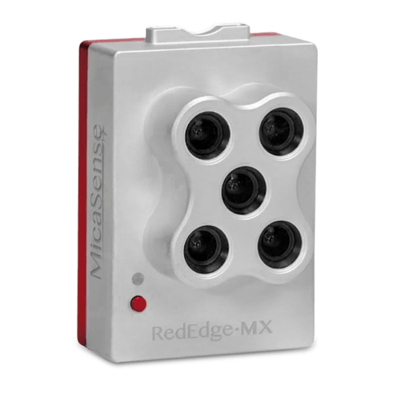
MicaSense RedEdge-MX Integration Manual
Multispectral camera
Hide thumbs
Also See for RedEdge-MX:
- Integration manual (23 pages) ,
- Integration manual (13 pages) ,
- Integration manual (14 pages)
Summary of Contents for MicaSense RedEdge-MX
- Page 1 RedEdge- M X Integration Guide Rev 01 MicaSense RedEdge-MX Multispectral Camera Integration Guide Revision: 01 – October 2018 MicaSense, Inc. Seattle, WA © 2018 MicaSense, Inc.
-
Page 2: Table Of Contents
Standalone Integration Using Camera, DLS, GPS Module 11 Integration with Aerial Platform for Triggering 12 Deep Integration with Host Platform 13 Addition of Top of Frame Capture to Integration 14 © 2018 MicaSense, Inc. Page 2 of 19 ... -
Page 3: Introduction And Scope
Rev 01 1. Introduction and Scope This document provides the information required for mechanical and electrical integration of a MicaSense RedEdge- M X multispectral camera onto a host aircraft. 2. Camera Dimensions and Mass ... -
Page 4: Lens And Imager Information
Do not use a screw that will extend into the threaded holes by more than 3 mm (0.125”). Use a washer or other spacer to ensure that the screws do not go into the camera too far. © 2018 MicaSense, Inc. Page 4 of 19 ... -
Page 5: Inputs And Outputs
The RedEdge- M X camera features 3 connectors for interface to peripherals and to the host aircraft. A fourth connector (USB Type A) is used for the Wi-Fi module (included). © 2018 MicaSense, Inc. Page 5 of 19 ... - Page 6 Pin # Signal 1 Trigger 2 Ground 3 Power Connector on Camera Hirose DF13A-3P-1.25H(51) Mating Connector Hirose DF13-3S-1.25C 28AWG wire recommended © 2018 MicaSense, Inc. Page 6 of 19 ...
- Page 7 When using a PWM signal as the trigger, the camera detects a transition from a “long” PWM to a “short” PWM (or vice-versa depending on the configuration setup of the camera) © 2018 MicaSense, Inc. Page 7 of 19 ...
- Page 8 Contact support@micasense.com if further information is needed. © 2018 MicaSense, Inc. Page 8 of 19 ...
-
Page 9: Downwelling Light Sensor 2 (Dls 2)
In addition, the DLS 2 provides GPS data to RedEdge-MX unless GPS data is provided from an external source as outlined earlier in this guide. If using an alternative GPS source, the ... - Page 10 RedEdge- M X Integration Guide Rev 01 Measurements and Attachment Points Height 14.03 mm Width 46.00 mm Length 63.50 mm Weight 49 g © 2018 MicaSense, Inc. Page 10 of 19 ...
- Page 11 The LED camera status indicator mimics the LED signals on RedEdge-MX. The signal types are outlined in the Sensor Firmware Guide. The camera trigger button will command a capture on the RedEdge-MX. This is useful for capturing a preflight image of the calibration panel. ...
- Page 12 It contains an integral GPS sensor that may be utilized for geotagging of the RedEdge-MX imagery if system GPS signals are not provided to the sensor by other means. Install the module where it will have a clear view of the sky, far away from any devices that ...
-
Page 13: Serial And Ethernet Data ("Comm")
5.3. Serial and Ethernet Data (“COMM”) This connector is available for tighter integration with host aircraft. It includes a standard TTL-level serial port as well as an Ethernet port. Documentation for the communications protocol is available by contacting MicaSense. Pin # Signal ... -
Page 14: Example Integrations
DLS. Automatic Capture/Triggering Options ● RedEdge-MX supports three methods for capturing images: Overlap, Timer, and External Trigger. To learn more about how to configure these settings, please see the Sensor Firmware Guide. ○ Overlap Mode (Recommended) ... - Page 15 I n overlap mode, when the aircraft climbs to within 50 meters below your target altitude, RedEdge-MX will start capturing and only take a capture if it has traveled forward enough distance to ensure the overlap percentage you have specified. When the sensor's altitude is below 50 meters from the target ...
-
Page 16: Integration With Aerial Platform For Triggering
(e.g. 1.0ms to 2.0ms) or long to short (e.g. 2.0ms to 1.0ms). These trigger settings are configurable via the WiFi interface, and are persistent once saved. © 2018 MicaSense, Inc. Page 16 of 19 ... -
Page 17: Deep Integration With Host Platform
MAVLink communication protocol, serial communications, and advanced Pixhawk or APM configuration. Ethernet connectivity is also an option - visit support.micasense.com for further resources on either of these two protocols. ... -
Page 18: Addition Of Top Of Frame Capture To Integration
DLS and the other end (with Ground and Pin 4 - see table in Section 5.1.2) would connect to the RTK/PPK GPS receiver or associated computer. © 2018 MicaSense, Inc. Page 18 of 19 ... - Page 19 ● The contents of this guide are subject to change without notice ● MicaSense, Inc. assumes no liability for incidental or consequential damages arising from the use of this product, and any claims by a third party. ● Copying of the contents of this guide, in whole or in part is prohibited under ...


Need help?
Do you have a question about the RedEdge-MX and is the answer not in the manual?
Questions and answers