
Related Manuals for Edgetech 2000-DSS


Summary of Contents for Edgetech 2000-DSS
- Page 1 2000-DSS COMBINED SONAR U S E R H A R D W A R E M A N U A L 0009335_REV_D 9/21/2018 EdgeTech 4 Little Brook Road West Wareham, MA 02576 Tel: (508) 291-0057 Fax: (508) 291-2491 www.EdgeTech.com...
- Page 2 The information, figures, and specifications in this manual are proprietary and are issued in strict confidence on condition that they not be copied, reprinted, or disclosed to a third party, either wholly or in part, without the prior, written consent of EdgeTech. Any reproduction of EdgeTech supplied software or file sharing is strictly prohibited.
-
Page 3: Attention - Read This First
ATTENTION – READ THIS FIRST! All personnel involved with the installation, operation, or maintenance of the equipment described in this manual should read and understand the warnings and cautions provided below. CAUTION! This equipment contains devices that are extremely sensitive to static electricity. -
Page 4: About This Document
Purpose of this Manual The purpose of this manual is to provide the user with information on the setup and use of EdgeTech’s 2000 Series. Although this manual encompasses the latest operational features of the 2000 Series, some features may be periodically upgraded. -
Page 5: Warranty Statement
All equipment manufactured by EdgeTech is warranted against defective components and workmanship for a period of one year after shipment. Warranty repair will be done by EdgeTech free of charge. Shipping costs are to be borne by the customer. Malfunction due to improper use is not covered in the warranty, and EdgeTech disclaims any liability for consequential damage resulting from defects in the performance of the equipment. -
Page 6: Hardware Variations And Compatibility
HARDWARE VARIATIONS AND COMPATIBILITY The 2000-DSS Combined Sonar contains both standard and proprietary hardware. At times, EdgeTech may change the standard components due to their availability or performance improvements. Although the component manufacturers—along with their models and styles—may change from unit to unit, replacement parts will generally be interchangeable. -
Page 7: Software Service Overview
Software Updates and Enhancements EdgeTech customers can download new software releases with all modifications and enhancements from the EdgeTech ftp site. Major software bugs, should they occur, will be reported directly to the customer. New software releases consist of the following: •... -
Page 8: Returned Material Authorization
Refer to RMA number on all documentation and correspondences. All returned materials must be shipped prepaid. Freight collect shipments will not be accepted. All equipment should be adequately insured for shipping, but equipment belonging to EdgeTech must be insured for full value. - Page 9 CUSTOMER SERVICE Customer service personnel at EdgeTech are always eager to hear from users of our products. Your feedback is welcome, and is a valuable source of information which we use to continually improve these products. Therefore we encourage you to contact EdgeTech Customer Service to offer any suggestions or...
-
Page 10: Company Background
USBL positioning systems, and bathymetric systems—that have become standards in the industry. EdgeTech has also consistently anticipated and responded to future needs through an active research and development program. Current efforts are focused on the application of cutting-edge CHIRP and acoustic technology. -
Page 11: Table Of Contents
2000 Series Applications ......................1-1 Main System Components ......................1-2 1.2.1 Topside Processor ......................... 1-2 1.2.2 2000 Digital Telemetry Link ....................1-3 1.2.3 2000-DSS Tow Vehicle ......................1-4 1.2.4 Tow Cables ..........................1-5 Optional Equipment ........................1-5 1.3.1 Magnetometer ........................1-6 1.3.2 Acoustic Tracking System ..................... - Page 12 Gaussian Shaped Amplitude Spectrum Outgoing Pulse ............1-8 SPECIFICATIONS ........................2-1 Topside Processor ........................2-1 2000 Digital Telemetry Link ....................... 2-3 2000-DSS Tow Vehicles ......................2-4 Cables ............................2-6 SETUP AND ACTIVATION ......................3-1 Unpacking and Inspection ......................3-1 Power Requirements ......................... 3-2 3.2.1...
- Page 13 xiii 3.8.2 Performing the Pre-Deployment Checks ................3-13 Tow Vehicle Deployment ......................3-16 3.10 Tow Vehicle Recovery ......................3-18 TECHNICAL DESCRIPTION ..................... 4-19 2000 Topside Processor ......................4-19 4.1.1 Topside Processor ....................... 4-19 4.1.2 2000 Digital Telemetry Link ....................4-20 4.1.2.1 Selecting Negative Edge Triggering for the Optional Responder .......
- Page 14 Insulation Resistance Breakdown ................6-11 6.3.8.4 Damaged Tow Cable Connector ................. 6-11 Part Numbers for Major Topside Components ............... 6-12 Part Numbers for Major 2000-DSS Tow Vehicle Components ..........6-12 SYSTEM RESTORE ........................ A-1 PRINTERS ..........................B-1 TOWING CHARACTERISTICS ....................C-1 Configuration 1 ..........................
- Page 15 C.14 Configuration 14 ........................C-16 C.15 Configuration 15 ........................C-17 C.16 Configuration 16 ........................C-18 C.17 Configuration 17 ........................C-19 C.18 Configuration 19 ........................C-20 C.19 Configuration 20 ........................C-21 C.20 Configuration 21 ........................C-22 C.21 Configuration 22 ........................C-23 C.22 Configuration 23 ........................
-
Page 16: List Of Figures
Figure 4-8: Tow Vehicle Interconnect Drawing..................4-26 Figure 4-9: Armored Cable, PMI Grip, Unterminated Topside ..............4-29 Figure 4-10: Test Cable ..........................4-30 Figure 5-1: 2000-DSS Tow Vehicle with Upper Half of Fiberglass Shell Removed ........5-3 2000-DSS COMBINED SONAR 0009335_REV_D... - Page 17 xvii END CAP REMOVAL HOLE (3) SOCKET HEAD CAP SCREW(3) Figure 5-2: Electronics Bottle Connector End Cap ..................5-4 Figure 5-3: Remote Desktop Icon ......................5-5 Figure 5-4: Remote Desktop Splash Screen ....................5-5 Figure 5-5: Remote Desktop Warning Screen .................... 5-6 Figure 5-6: Closing Sonar.exe ........................
- Page 18 Figure C-2: Tow Cable Length Versus Depth—Cable A320327, 500 Meters ..........C-3 Figure C-3: Tow Cable Shape and Tow Vehicle Position—Cable A320327, 1000-Meters ......C-4 Figure C-4: Tow Cable Length Versus Depth—Cable A320327, 1000 Meters ........... C-4 2000-DSS COMBINED SONAR 0009335_REV_D...
- Page 19 Table 6-2: 2000 Digital Telemetry Link Troubleshooting Guide ..............6-4 Table 6-3: Major Topside Components and Part Numbers ..............6-12 Table 6-4: Major 2000-DSS Tow Vehicle Components and Part Numbers ..........6-13 Table B-1: Printer Requirements ....................... B-1 Table C-1: Tow Cable Characteristics ......................C-2...
-
Page 21: Overview
(CW) systems. The 2000-DSS Combined Side Scan Sonar and Sub-Bottom Profiling System is available with a choice of two dual frequency configurations for the side scan sonar: 100/400 kHz and 300/600 kHz. The 2000-DSS uses a high frequency, 2–16 kHz sub-bottom sonar for higher resolution sub-bottom imaging in water... -
Page 22: Main System Components
The 2000-DSS Combined Side Scan Sonar and Sub-Bottom Profiling System is composed of two main components: the Rack Mount Topside and the 2000-DSS Tow Vehicle. The Rack Mount Topside is made up of a Topside Processor and a 2000 Digital Telemetry Link installed in a 19-inch rack enclosure, along 1-2. -
Page 23: 2000 Digital Telemetry Link
1.2.2 2000 Digital Telemetry Link The 2000 Digital Telemetry Link provides downlink telemetry to the tow vehicle for sonar control and receives uplink side scan and sub bottom data, sensor data and status information from the tow vehicle. It interfaces with the Topside Processor over a 10/100/1000BaseT Ethernet connection and includes tow vehicle and DC power supplies, an asynchronous digital subscriber line (ADSL) modem and an Ethernet switch, all within a single 19-inch 2U chassis. -
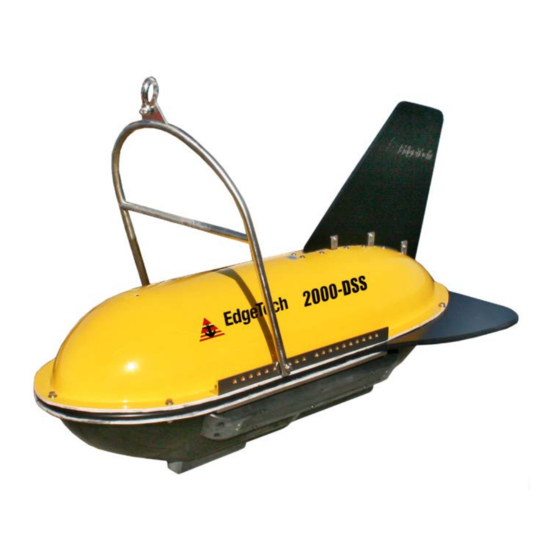
Page 24: 2000-Dss Tow Vehicle
1-3. IGURE The 2000-DSS Tow Vehicle sub-bottom sonar operates over a frequency range of 2–16 kHz, has a 2000- meter depth rating, and is designed primarily for applications requiring higher resolution sub-bottom imagery. It is hydrodynamically stabilized and includes the sub-bottom transducer and two sub bottom hydrophone arrays mounted under an acoustic baffle. -
Page 25: Tow Cables
1.2.4 Tow Cables Both Kevlar reinforced and armored tow cables are available separately, terminated at both ends or just at the tow vehicle end. The tow cables are used to connect to and tow the tow vehicle. A Kevlar reinforced tow cable is shown 1-4. -
Page 26: Magnetometer
1.4 Full Spectrum Chirp Technology Overview EdgeTech's Full Spectrum Chirp technology has several distinct advantages over conventional side scan and sub-bottom profiling systems. These benefits include the use of separate sub-bottom acoustic projectors and receivers to enable simultaneous transmission and reception of acoustic signals, high... -
Page 27: Separate Sub-Bottom Acoustic Projectors And Receivers
sediment layering and display of along track and across track imagery, reduction of side lobes for minimal reception of undesired echoes, additional processing gain for energy efficiency, and a Gaussian shaped amplitude spectrum of the outgoing pulse to preserve resolution and bandwidth with attenuation. 1.4.1 Separate Sub-Bottom Acoustic Projectors and Receivers The side scan sonar uses a line array of piezoelectric elements to both transmit and receive the acoustic signals, one on the port side of the tow vehicle and one on the starboard side. -
Page 28: Reduction Of Side Lobes
As a wavelet with a Gaussian shaped spectrum is attenuated by the sediment, energy is lost but its bandwidth is nearly preserved. Therefore, even after being attenuated, the acoustic pulse has approximately the same resolution as an unattenuated pulse. 2000-DSS COMBINED SONAR 0009335_REV_D... -
Page 29: Specifications
2.0 SPECIFICATIONS The specifications for the EdgeTech 2000 Series Combined Side Scan Sonar and Sub-Bottom Profiling System include electrical, mechanical and environmental characteristics for the following components: • Topside Processor • 2000 Digital Telemetry Link • 2000-DSS Tow Vehicle NOTE: All specifications are subject to change without notice. -
Page 30: Table 2-1: Topside Specifications
Total shipping weight of the 2000 Topside Processor and the 2000 Digital Telemetry Link mounted inside a 19-inch rack enclosure with the keyboard, the trackball and one monitor. Shipped in a sealed high impact polyurethane case. Rack enclosure weight is 41 kg (90 lb). 2000-DSS COMBINED SONAR 0009335_REV_D... -
Page 31: 2000 Digital Telemetry Link
2.2 2000 Digital Telemetry Link The specifications for the 2000 Digital Telemetry Link are shown in 2-2. ABLE SPECIFICATION VALUE Size: 8.3 cm (3.25 in.) high, 48.3 cm (19 in.) wide; 43.2 cm (17 in.) deep Weight: 6.4 kg (14 lbs.) Case type: EIA RS-310C 19-inch standard rackmount Case construction:... -
Page 32: 2000-Dss Tow Vehicles
2.0 SPECIFICATIONS 2.3 2000-DSS Tow Vehicles The specifications for the 2000-DSS Tow Vehicle is shown in 2-3. ABLE SPECIFICATION VALUE G E N E R A L S P E C I F I C A T I O N S 145.0 cm (57.1 in.) long... - Page 33 SPECIFICATION VALUE 500 m (100 kHz) Expanded Operating 230 m (300 kHz) ranges 150 m (400 kHz) (per side): 120 m (600 kHz) 4 j (100 kHz) 3 j (300 kHz) Output pulse energy: 2 j (400 kHz) 1 j (600 kHz) Up to 20 ms (100 kHz) Up to 12 ms (300 kHz) Pulse length:...
-
Page 34: Cables
<8°, 2–10 kHz <7°, 2–12 kHz Optimum tow height: 3–5 m above sea floor Transmitters: Receive arrays: Table 2-3: 2000-DSS Towfish Specifications 2.4 Cables For cable specifications, see the following diagrams in section 4.0: • IGURE • 4-10 IGURE Vertical resolution is the smallest distinguishable distance between the peaks of two reflections that can be displayed on the screen as separate reflectors. -
Page 35: Setup And Activation
Also check the packing list and verify that all the items on the list are included. Again, if any damage is found, report it to the carrier and to EdgeTech. If any items are missing, immediately contact EdgeTech. Do not install or operate any equipment that appears to be damaged. Although the items shipped will vary, depending on the customer requirements, the 2000 Series Combined Side Scan Sonar and Sub-Bottom Profiling System typically includes, as a minimum, the items listed below. -
Page 36: Power Requirements
AC POWER CORD WIRE COLOR FUNCTION Black AC line White AC neutral Green Earth ground Table 3-1: AC Power Cord Wiring NOTE: The 2000 Topside Processor is shipped configured for the end user’s country voltage requirements. 2000-DSS Combined Sonar 0009335_REV_D... -
Page 37: Navigation Interface
3.3 Navigation Interface The 2000-DSS Combined Side Scan Sonar and Sub-Bottom Profiling System accepts most standard National Marine Electronics Association (NEMA) 0183 message sentence formats from a connected global positioning system (GPS) or integrated navigation system. 3.4 Topside Location—Best Practices The Rack Mount topside should be located and set up in a dry, sheltered area that is protected from weather and water spray and where the temperature is consistently between 0°C and 40°C (32°F and... -
Page 38: Figure 3-1: Rack Mount Topside Front Panel
LED STATUS 2000-DL INDICATORS POWER SWITCH 2000-DL REMOVABLE DIGITAL LINK HARD DRIVE DVD-RW DRIVE USB INPUTS 2000 TOPSIDE COMPUTER SYSTEM POWER LED (LEFT) HARD DRIVE LED SYSTEM RESET BUTTON AND BUTTON (RIGHT) Figure 3-1: Rack Mount Topside Front Panel... -
Page 39: Figure 3-2: Rack Mount Topside Back Panel
SEA CABLE SYNC CONNECTOR 2000-DL DATA LINK INPUT CONNECTOR AC POWER INPUT AND SWITCH DISPLAY PORT VIDEO (2) AC POWER INPUT AND SWITCH COM PORTS (6) ETHERNET INPUTS USB 2.0 AND 3.0 DVI MONITOR PORT Figure 3-2: Rack Mount Topside Back Panel... -
Page 40: Topside Computer Controls And Indicators
Rocker switch. Switches AC power to the POWER switch on the front panel of the 2000-DL. This switch can be left in the on position at all times. POWER: Rocker switch. Turns the 2000-DL on or off. PWR: Green indicator. Illuminated when the 2000-DL is on. 2000-DSS Combined Sonar 0009335_REV_D... -
Page 41: Tcp/Ip Address Settings
LAN: Green indicator. Flashes continuously when an Ethernet connection is established. LINK: Green indicator. Flashes while the 2000-DL is establishing a reliable communications link with the side scan sonar. Illuminates continuously when a reliable communications link with the sonar is established. FISH POWER: Red indicator. -
Page 42: Connecting The System Components
When connecting the system components, refer to sub-section 3.5.1 for the location and description of the connectors. The cables used with the system are shown in 3-3. IGURE Figure 3-3: System Cables 2000-DSS Combined Sonar 0009335_REV_D... -
Page 43: Connecting And Attaching The Tow Cable To The Tow Cable
3.7.1 Connecting and Attaching the Tow Cable to the Tow Cable A tow cable is shown connected and attached to a 2000-DSS Tow Vehicle in 3-4. For shallow water IGURE surveys, a tow rope with a working load of 2000 lbs. or more and a breaking strength of at least 6000 lbs. -
Page 44: Connecting The 2000 Topside Processor
11. Connect an AC power cord to the LINE VAC connector of the 2000 Digital Telemetry Link and to the AC power source. 12. Connect an AC power cord to each of the LCD monitors and to the AC power source. 2000-DSS Combined Sonar 0009335_REV_D... -
Page 45: System Activation And Test
3. Turn on the SYSTEM POWER switch on the front panel. The SYSTEM POWER indicator should illuminate, and the HDD indicator should flash while the Windows desktop opens. Then the EdgeTech DISCOVER 2000-C Dual Frequency Side Scan and DISCOVER Sub Bottom software open to the Main windows as shown in 3-5. -
Page 46: Figure 3-5: Discover 2000-C Dual Frequency Side Scan & Discover Sub-Bottom Windows
LINK indicator should flash while a reliable communications link with the tow vehicle is being established and then illuminate continuously when the link is found. In addition, the NET indicator on the Status bar at the bottom of the Main window should indicate as follows: 2000-DSS Combined Sonar 0009335_REV_D... -
Page 47: Performing The Pre-Deployment Checks
3-13 3.8.2 Performing the Pre-Deployment Checks The pre-deployment checks should be performed after the system is activated and before the tow vehicle is deployed. These checks are performed for both the side scan and sub-bottom sonars and involve verifying that data can be recorded and played back in DISCOVER; rubbing your hand on the side scan transducer arrays and tapping the sub-bottom hydrophone arrays while observing the Sonar displays in the DISCOVER Main windows;... -
Page 48: Figure 3-7: Options Dialog Box, Sonar Control Tab-Discover Sub Bottom
The Display tab shown in opens. IGURE 11. On the Display tab, set the Gain to either 0 or -3 dB, and then click Norm. 12. Close the Options dialog box. Figure 3-8: Options Dialog Box, Display Tab—DISCOVER Sub-Bottom 2000-DSS Combined Sonar 0009335_REV_D... - Page 49 3-15 CAUTION! Do not allow the sub-bottom transducer on the tow vehicle to continuously transmit in air for an extended period as damage to the transducer could occur. 13. From the Sonar menu, choose Sonar On. When the sonar is on, a check mark appears next to the menu item.
-
Page 50: Tow Vehicle Deployment
Doing so can degrade the sonar imagery. Verify that the tow vehicle is as level as possible when towing it. NOTE: For detailed towing characteristics for the 2000-DSS Tow Vehicle with several tow cable types and lengths and tow vehicle speeds, refer to appendix C.0. -
Page 51: Figure 3-9: 2000-Dss Tow Vehicle Being Deployed
3-17 Figure 3-9: 2000-DSS Tow Vehicle being Deployed To deploy the tow vehicle: 1. With the survey vessel under way at up to two knots, slowly and carefully lower the tow vehicle into the water, well away from the propeller. Do not let the tow vehicle strike the hull of the survey vessel. -
Page 52: Tow Vehicle Recovery
6. Disconnect the tow cable from the tow cable connector. 7. Install the dummy plug on the tow cable connector. 8. Refer to sub-section for instructions on how to clean and inspect the tow vehicle, the tow cable and the underwater connectors after use. 2000-DSS Combined Sonar 0009335_REV_D... -
Page 53: Technical Description
This section provides an overall general description of the hardware elements comprising the 2000 Topside Processor and the 2000-DSS Tow Vehicle of the 2000 Series Combined Side Scan Sonar and Sub- Bottom Profiling System. This information, which includes block diagrams, board descriptions, chassis photos, component callouts, and wiring diagrams, can be useful for troubleshooting purposes and installing optional equipment. -
Page 54: 2000 Digital Telemetry Link
Power board to provide Power board diagnostics, tow vehicle power control, positive and negative trigger edge selection, and sensor monitoring. An Ethernet connection to the Net Burner board is provided on J3 from the ADSL Modem board. Power is input from the Power board. 2000-DSS Combined Sonar 0009335_REV_D... -
Page 55: Selecting Negative Edge Triggering For The Optional Responder
Selecting Negative Edge Triggering for the Optional Responder The 2000-DSS system has the ability to be configured with an optional responder in the tow vehicle. If ordered from the factory with a responder installed, the 2000-DL digital telemetry link will have a jumper 4-2, and the customer does not need to take any further steps. - Page 56 Figure 4-2: 2000 Digital Telemetry Link Electronics Block Diagram...
- Page 57 Figure 4-3: 2000 Digital Telemetry Link Wiring Diagram...
-
Page 58: Tow Vehicle
4-24 4.0: TECHNICAL DESCRIPTION 4.2 Tow Vehicle A photo of the 2000-DSS Tow Vehicle electronics chassis is shown 4-7, and a block diagram and IGURE interconnect drawing are in 4-8, respectively. The electronics chassis contains all of IGURE IGURE the tow vehicle circuit boards along with the optional pressure sensor. The circuit boards are the... - Page 59 Figure 4-4: Tow Vehicle Electronic Block Diagram...
- Page 60 Figure 4-5: Tow Vehicle Interconnect Drawing...
- Page 61 4-27 Amplified transmit signals are output to the transducer arrays or received signals are input from the transducer arrays as follows: • Port transducer array receive • J14: Starboard transducer array receive The T/R Switch board also includes four noise reducing receiver preamplifiers, one each for the high and low frequency port transducer arrays and one each for the high and low frequency starboard transducer arrays.
-
Page 62: Cables
Outline drawings of the optionally available tow cable and test cable are listed below along with their corresponding figure numbers. • 4-9: A , PMI G IGURE RMORED ABLE NTERMINATED OPSIDE • 4-10: T IGURE ABLE 2000-DSS COMBINED SONAR 0009335_REV_D... - Page 63 Figure 4-6: Armored Cable, PMI Grip, Unterminated Topside...
- Page 64 Figure 4-7: Test Cable...
-
Page 65: Maintenance
This section provides some maintenance recommendations and includes instructions on how to disassemble and reassemble the 2000-DSS Tow Vehicle should it be required to access and remove the electronics chassis in the electronics bottle. In addition, lists of major components for the 2000 Topside Processor and the 2000-DSS Tow Vehicles are included. -
Page 66: Storage
High voltages that can cause injury or death are present in the tow vehicle. Turn off both the Topside Processor and the 2000 Digital Telemetry Link and disconnect the tow cable before disassembling the tow vehicle. 2000-DSS COMBINED SONAR 0009335_REV_D... -
Page 67: Disassembling The Tow Vehicle
5.3.1 Disassembling the Tow Vehicle To disassemble the tow vehicle: Place the tow vehicle on a clean, dry, flat surface. For the 2000-DSS Tow Vehicle, use the 9/16-inch wrench and remove the three sets of bolts, washers and self-locking nuts in the bow. -
Page 68: Reassembling The Tow Vehicle
IGURE Calibrating the Compass The compass is calibrated at the EdgeTech manufacturing facility. Should the compass in the towfish lose its calibration for any reason in the field, it may be necessary to recalibrate it. This is accomplished by accessing the embedded Windows installation in the towfish itself via a remote desktop application on the Rack Mount Topside. -
Page 69: Figure 5-3: Remote Desktop Icon
Furthermore, it is necessary to physically move the towfish around in different positions for the compass within it to establish the necessary reference points. The support of at least two survey technicians, and a rotating table (as shown in the procedure to follow) or winch for hoisting and rotating the towfish are essential. -
Page 70: Figure 5-5: Remote Desktop Warning Screen
IGURE Figure 5-5: Remote Desktop Warning Screen 4. In the remote desktop program, the embedded Windows installation in the towfish will become accessible. Shut down the Sonar.exe application running (see below): IGURE Figure 5-6: Closing Sonar.exe 2000-DSS COMBINED SONAR 0009335_REV_D... -
Page 71: Figure 5-7: Tera Term Icon
5. On this desktop, click on the Tera Term command console icon 5-7). At the splash screen IGURE 5-8), click OK. IGURE Figure 5-7: Tera Term Icon Figure 5-8: Tera Term Splash Screen... -
Page 72: Figure 5-9. Terra Term Port Set-Up
6. Establish communications with the SSAHRS and verify via a serial console. Figure 5-9. Terra Term Port Set-up Figure 5-10. Motion Sensor Serial Output 7. Stop the device and retrieve the current level 2 (factory) calibration using the following two commands. stop <CR> getLevel2CompassCalibration <CR> 2000-DSS COMBINED SONAR 0009335_REV_D... -
Page 73: Figure 5-11. Motion Sensor Calibration Result
8. Ensure that the points are 0, the error percentage is 100.0%, the hard iron values are all 0.0, and that the soft iron values are an identity matrix (see 5-11). IGURE Figure 5-11. Motion Sensor Calibration Result If for some reason they are not; reset SSAHRS with the following command and then cycle power. setLevel2CompassCalibration,factory2015,0,100.0,50.0,0,0,0, 1,0,0,0,1,0,0,0,1 <CR>... -
Page 74: Figure 5-13: Compass Calibration Table
<CR> c. Verify Factory Compass Calibration has been set by issuing the following commands: Stop <CR> getLevel2CompassCalibration 13. At this point, the SSAHRS calibration is complete. Close out of remote desktop. 2000-DSS COMBINED SONAR 0009335_REV_D... -
Page 75: Changing The Angle Of Declination
Changing the Angle of Declination The compass' angle of declination is set to true north at the EdgeTech facility. However, to provide a more accurate target location, it is necessary to enter the known magnetic declination for the survey location into the compass as follows: 14. - Page 76 Declination for your location can be found by going to the following website: http://www.ngdc.noaa.gov/geomag-web/#declination Here is an example of how using this website can help you to determine your angle of deviation: Zipcode 02360 was inserted, then "Get & Add Lat/Lon" was selected: 2000-DSS COMBINED SONAR 0009335_REV_D...
-
Page 77: Figure 5-16: Magnetic Declination Estimated Value Screen
5-13 Figure 5-16: Magnetic Declination Estimated Value Screen... -
Page 78: Figure 5-17: Angle Of Declination Calculated
The Declination Angle received was 14.47 degrees. This is the angle that will be entered into the TeraTerm command screen. • Enter the Declination Angle using the command: setDeclination, 14.47 <CR> Verify entry of declination Angle using the command: 2000-DSS COMBINED SONAR 0009335_REV_D... - Page 79 5-15 getDeclination <CR> Figure 5-18...
-
Page 81: Troubleshooting
6.0 TROUBLESHOOTING In the unlikely chance that some operational or performance problems occur with the 2000 Series Combined Side Scan Sonar and Sub-Bottom Profiling System, it may be possible to correct them using the troubleshooting guides in the following pages. For the Topside Processor and the 2000 Digital Telemetry Link, tabular troubleshooting guides are provided in 6-2, respectively. -
Page 82: 2000 Digital Telemetry Link Troubleshooting Guide
There is no connection Check LAN connections between Digital Telemetry Link does not between the 2000 Digital the 2000 Digital Telemetry Link illuminate when the unit is turned Telemetry Link and the and the Topside Processor. Topside Processor. 2000-DSS COMBINED SONAR 0009335_REV_D... - Page 83 SYMPTOM PROBABLE CAUSE CORRECTIVE ACTION Open the 2000 Digital Telemetry The indicator is not Link and check the indicator and operating. wiring. Tow cable between the 2000 Digital Telemetry Link Check connections and tow and tow vehicle is cable. The green LINK indicator on the disconnected or faulty.
-
Page 84: Tow Vehicle Troubleshooting Guide
If the above checks do not identify or remedy the problem, attempt to isolate the failure to one of the major system components: the sonar processor, the modem/power unit, the tow vehicle, or the tow cable. The following presents various operational problems and general comments on where to look and what to look for. 2000-DSS COMBINED SONAR 0009335_REV_D... -
Page 85: Equipment Required
3 kHz means that self-test has failed. These tones are generated in software in the tow vehicle and replicated on the surface when an EdgeTech topside processor is used to access the Tow vehicle computer subsystem using the Remote Desktop application. The Self-Test PASS tones repeat until data linkup has... -
Page 86: Topside Power Unit
A dark band should appear on the sonar processor screen corresponding to the side rubbed. Data throughput rates on the uplink (vehicle to topside) can be critical in getting smooth data from the tow vehicle. The data throughput rate can be checked using EdgeTech supplied utilities at each end of the link The sockBlast application is used to test network throughput between the tow vehicle and the Topside Processor. -
Page 87: Tow Vehicle
Figure 6-1: sockBlast Window Two copies must be run one on each computer. One serves as the client (topside) and the other as the server (tow vehicle). Since the client connects to the server, the Create Client (topside) address must be the TCP/IP address of the server (tow vehicle) machine, which is 192.9.0.99. -
Page 88: No Sonar Data
+12 VDC +/-0.6V TP12 -12 VDC +/-0.6V TP12 +27 VDC +/-0.6V TP10 TP12 +48 VDC +/-2.0V Other voltages to check on the SSB board and labeled as such are: Supply +3.3 VDC +/-0.1 +5 VDC +/-0.2V 2000-DSS COMBINED SONAR 0009335_REV_D... -
Page 89: Ssb Board Test Points
+12 VDC +/-0.6V -12 VDC +/-0.6V Test Lights: 1. Power Distribution Board. Monitor the +400 volt D4 and +48 volt D8 LED's. They should be on steady. 2. SSB Board. There are two LED's of interest. 'LED A' flashes when 120 kHz is transmitting. 'LED B' flashes when 410 kHz is transmitting. -
Page 90: Other Checks
6. Add the measurements of 4) and 5) above, subtract the measurement of 2), and divide the result by 2. Rs =_________________ 7. Subtract the value of 6) from the measured values of 4) and 5). R1 =_________________ R2 =_________________ 2000-DSS COMBINED SONAR 0009335_REV_D... -
Page 91: Open Wire
6-11 8. The distance to the short from end #1 is the ratio of (R1/R1+R2) times the total cable length. Recheck from end #2 which is (R2/R1+R2) times the cable length. 6.3.8.2 Open Wire An open wire in a cable is much more difficult to locate than a short circuit; therefore, a capacitance bridge is recommended. -
Page 92: Part Numbers For Major Topside Components
Assembly Top Power Supply 0011860 Power Supply 0006372 Ethernet Switch 0005088 Table 6-3: Major Topside Components and Part Numbers 6.5 Part Numbers for Major 2000-DSS Tow Vehicle Components COMPONENT DESCRIPTION EDGETECH PART NUMBER RUDDER 2000 DSS 0006596 BRACKET RUDDER 2000 DSS 0003403... -
Page 93: Table 6-4: Major 2000-Dss Tow Vehicle Components And Part Numbers
END CAP REAR 05 INCH 3000M AL 0005069 PCB ASSY SUB CAPACITOR BANK 2000 DSS 0009230 ASSY SUB BOARDSET CPU COMX ATOM MBT10 E3825 0018350 MEMORY FLASH GENERIC R-DRIVE IMAGE KONTRON E3815 CPU 0017144 Table 6-4: Major 2000-DSS Tow Vehicle Components and Part Numbers... -
Page 95: System Restore
A.0 SYSTEM RESTORE The following section outlines the procedures for backing up and restoring the system drive. CAUTION! All data will be lost upon restoring the system to factory settings. Be sure to backup all data before preforming the procedure below. -
Page 97: Printers
B.0 PRINTERS A number of different printers are available for connecting to the 2000 Series Combined Side Scan Sonar and Sub-Bottom Profiling System. All of these printers connect to the USB connector on the back of the Topside Computer. Of the available printers, the following are recommended for best results: •... -
Page 99: Towing Characteristics
C.0 TOWING CHARACTERISTICS This section includes graphical plots representing the towing characteristics of the 2000-DSS Tow Vehicle for various cable lengths, tow vehicle speeds and tow vehicle depths. There are a total of 32 plot C-1. These plots are available for equipment selection purposes only. In... -
Page 100: Table C-1: Tow Cable Characteristics
C-18 6000 C-19 7000 C-20 8000 C-21 9000 C-22 C-23 1000 C-24 2000 C-25 3000 C-26 4000 C-27 A302799 5000 C-28 6000 C-29 7000 C-30 8000 C-31 9000 C-32 10000 C-33 Table C-1: Tow Cable Characteristics 2000-DSS COMBINED SONAR 0009335_REV_D... -
Page 101: Figure C-1: Tow Cable Shape And Tow Vehicle Position-Cable A320327, 500 Meters
C.1 Configuration 1 Figure C-1: Tow Cable Shape and Tow Vehicle Position—Cable A320327, 500 Meters Figure C-2: Tow Cable Length Versus Depth—Cable A320327, 500 Meters... -
Page 102: Figure C-3: Tow Cable Shape And Tow Vehicle Position-Cable A320327, 1000-Meters
C.0: TOWING CHARACTERISTIC C.2 Configuration 2 Figure C-3: Tow Cable Shape and Tow Vehicle Position—Cable A320327, 1000-Meters Figure C-4: Tow Cable Length Versus Depth—Cable A320327, 1000 Meters 2000-DSS COMBINED SONAR 0009335_REV_D... - Page 103 C.3 Configuration 3 Figure C-1: Tow Cable Shape and Tow Vehicle Position—Cable A320327, 2000 Meters Figure C-2: Tow Cable Length vs Depth—Cable A320327, 2000 Meters...
- Page 104 C.0: TOWING CHARACTERISTIC C.4 Configuration 4 Figure C-3: Tow Cable Shape and Tow Vehicle Position—Cable A320327, 3000 Meters Figure C-4: Tow Cable Length Versus Depth—Cable A320327, 3000 Meters 2000-DSS COMBINED SONAR 0009335_REV_D...
- Page 105 C.5 Configuration 5 Figure C-5: Tow Cable Shape and Tow Vehicle Position—Cable A320327, 4000 Meters Figure C-6: Tow Cable Length vs Depth—Cable A320327, 4000 Meters...
- Page 106 C.0: TOWING CHARACTERISTIC C.6 Configuration 6 Figure C-7: Tow Cable Shape and Tow Vehicle Position—Cable A320327, 5000 Meters Figure C-8: Tow Cable Length Versus Depth—Cable A320327, 5000 Meters 2000-DSS COMBINED SONAR 0009335_REV_D...
- Page 107 C.7 Configuration 7 Figure C-9: Tow Cable Shape and Tow Vehicle Position—Cable A320327, 6000 Meters Figure C-10: Tow Cable Length Versus Depth—Cable A320327, 6000 Meters...
- Page 108 C.0: TOWING CHARACTERISTIC C-10 C.8 Configuration 8 Figure C-11: Tow Cable Shape and Tow Vehicle Position—Cable A320327, 7000 Meters Figure C-12: Tow Cable Length Versus Depth—Cable A320327, 7000 Meters 2000-DSS COMBINED SONAR 0009335_REV_D...
- Page 109 C-11 C.9 Configuration 9 Figure C-13: Tow Cable Shape and Tow Vehicle Position—Cable A320327, 8000 Meters Figure C-14: Tow Cable Length Versus Depth—Cable A320327, 8000 Meters...
- Page 110 C.0: TOWING CHARACTERISTIC C-12 C.10 Configuration 10 Figure C-15: Tow Cable Shape and Tow Vehicle Position—Cable A320327, 9000 Meters Figure C-16: Tow Cable Length Versus Depth—Cable A320327, 9000 Meters 2000-DSS COMBINED SONAR 0009335_REV_D...
- Page 111 C-13 C.11 Configuration 11 Figure C-17: Tow Cable Shape and Tow Vehicle Position—Cable A320327, 10000 Meters Figure C-18: Tow Cable Length Versus Depth—Cable A320327, 10000 Meters...
- Page 112 C.0: TOWING CHARACTERISTIC C-14 C.12 Configuration 12 Figure C-19: Tow Cable Shape and Tow Vehicle Position—Cable A301241, 500 Meters Figure C-20: Tow Cable Length Versus Depth—Cable A301241, 500 Meters 2000-DSS COMBINED SONAR 0009335_REV_D...
- Page 113 C-15 C.13 Configuration 13 Figure C-21: Tow Cable Shape and Tow Vehicle Position—Cable A301241, 1000 Meters Figure C-22: Tow Cable Length Versus Depth—Cable A301241, 1000 Meters...
- Page 114 C.0: TOWING CHARACTERISTIC C-16 C.14 Configuration 14 Figure C-23: Tow Cable Shape and Tow Vehicle Position—Cable A301241, 2000 Meters Figure C-24: Tow Cable Length Versus Depth—Cable A301241, 2000 Meters 2000-DSS COMBINED SONAR 0009335_REV_D...
- Page 115 C-17 C.15 Configuration 15 Figure C-25: Tow Cable Shape and Tow Vehicle Position—Cable A301241, 3000 Meters Figure C-26: Tow Cable Length Versus Depth—Cable A301241, 3000 Meters...
- Page 116 C.0: TOWING CHARACTERISTIC C-18 C.16 Configuration 16 Figure C-27: Tow Cable Shape and Tow Vehicle Position—Cable A301241, 5000 Meters Figure C-28: Tow Cable Length Versus Depth—Cable A301241, 5000 Meters 2000-DSS COMBINED SONAR 0009335_REV_D...
- Page 117 C-19 C.17 Configuration 17 Figure C-29: Tow Cable Shape and Tow Vehicle Position—Cable A301241, 6000 Meters Figure C-30: Tow Cable Length Versus Depth—Cable A301241, 6000 Meters...
- Page 118 C.0: TOWING CHARACTERISTIC C-20 C.18 Configuration 19 Figure C-31: Tow Cable Shape and Tow Vehicle Position—Cable A301241, 7000 Meters Figure C-32: Tow Cable Length Versus Depth—Cable A301241, 7000 Meters 2000-DSS COMBINED SONAR 0009335_REV_D...
- Page 119 C-21 C.19 Configuration 20 Figure C-33: Tow Cable Shape and Tow Vehicle Position—Cable A301241, 8000 Meters Figure C-34: Tow Cable Length Versus Depth—Cable A301241, 8000 Meters...
- Page 120 C.0: TOWING CHARACTERISTIC C-22 C.20 Configuration 21 Figure C-35: Tow Cable Shape and Tow Vehicle Position—Cable A301241, 9000 Meters Figure C-36: Tow Cable Length Versus Depth—Cable A301241, 9000 Meters 2000-DSS COMBINED SONAR 0009335_REV_D...
- Page 121 C-23 C.21 Configuration 22 Figure C-37: Tow Cable Shape and Tow Vehicle Position—Cable A302799, 500 Meters Figure C-38: Tow Cable Length Versus Depth—Cable A302799, 500 Meters...
- Page 122 C.0: TOWING CHARACTERISTIC C-24 C.22 Configuration 23 Figure C-39: Tow Cable Shape and Tow Vehicle Position—Cable A302799, 1000 Meters Figure C-40: Tow Cable Length Versus Depth—Cable A302799, 1000 Meters 2000-DSS COMBINED SONAR 0009335_REV_D...
- Page 123 C-25 C.23 Configuration 24 Figure C-41: Tow Cable Shape and Tow Vehicle Position—Cable A302799, 2000 Meters Figure C-42: Tow Cable Length Versus Depth—Cable A302799, 2000 Meters...
- Page 124 C.0: TOWING CHARACTERISTIC C-26 C.24 Configuration 25 Figure C-43: Tow Cable Shape and Tow Vehicle Position—Cable A302799, 3000 Meters Figure C-44: Tow Cable Length Versus Depth—Cable A302799, 3000 Meters 2000-DSS COMBINED SONAR 0009335_REV_D...
- Page 125 C-27 C.25 Configuration 26 Figure C-45: Tow Cable Shape and Tow Vehicle Position—Cable A302799, 4000 Meters Figure C-46: Tow Cable Length Versus Depth—Cable A302799, 4000 Meters...
- Page 126 C.0: TOWING CHARACTERISTIC C-28 C.26 Configuration 27 Figure C-47: Tow Cable Shape and Tow Vehicle Position—Cable A302799, 5000 Meters Figure C-48: Tow Cable Length Versus Depth—Cable A302799, 5000 Meters 2000-DSS COMBINED SONAR 0009335_REV_D...
- Page 127 C-29 C.27 Configuration 28 Figure C-49: Tow Cable Shape and Tow Vehicle Position—Cable A302799, 6000 Meters Figure C-50: Tow Cable Length Versus Depth—Cable A302799, 6000 Meters...
- Page 128 C.0: TOWING CHARACTERISTIC C-30 C.28 Configuration 29 Figure C-51: Tow Cable Shape and Tow Vehicle Position—Cable A302799, 7000 Meters Figure C-52: Tow Cable Length Versus Depth—Cable A302799, 7000 Meters 2000-DSS COMBINED SONAR 0009335_REV_D...
- Page 129 C-31 C.29 Configuration 30 Figure C-53: Tow Cable Shape and Tow Vehicle Position—Cable A302799, 8000 Meters Figure C-54: Tow Cable Length Versus Depth—Cable A302799, 8000 Meters...
- Page 130 C.0: TOWING CHARACTERISTIC C-32 C.30 Configuration 31 Figure C-55: Tow Cable Shape and Tow Vehicle Position—Cable A302799, 9000 Meters Figure C-56: Tow Cable Length Versus Depth—Cable A302799, 9000 Meters 2000-DSS COMBINED SONAR 0009335_REV_D...
- Page 131 C-33 C.31 Configuration 32 Figure C-57: Tow Cable Shape and Tow Vehicle Position—Cable A302799, 10000 Meters Figure C-58: Tow Cable Length Versus Depth—Cable A302799, 10000 Meters...
Need help?
Do you have a question about the 2000-DSS and is the answer not in the manual?
Questions and answers