
Related Manuals for curt VENTURER

Summary of Contents for curt VENTURER
- Page 1 VENTURER VENTURER BRAKE CONTROL INSTALLATION AND USER GUIDE For use with 12 volt negative ground systems only For trailers with two to six brakes Read, follow and save this guide for future reference 51110-INS-R1 • PAGE 1...
- Page 2 One or more of the following may be needed to complete installation: • Brake control connection harness, supplied with the tow vehicle (if equipped) • CURT quick plug - custom connector for specific vehicles. See catalog for availability • CURT part# 51515 - male quick plug with pigtails • CURT part# 51500 - brake control wiring kit...
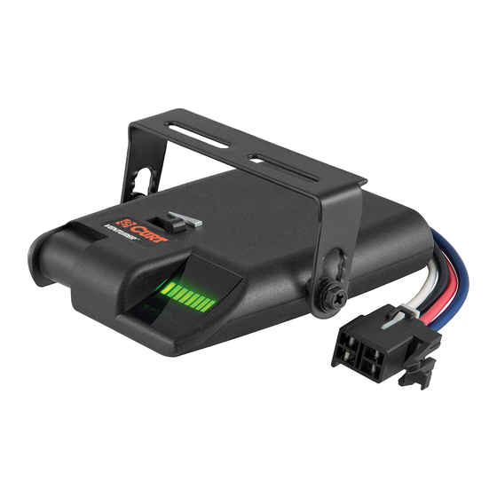
- Page 3 Controls and Components 1. Display 2. Sync adjustment 3. Output adjustment 4. Manual control lever 5. Quick plug connector PAGE 3...
- Page 4 Disconnect Indication Should a trailer disconnect occur, either unplugged or wiring failure, the status LED will glow steady red. It will remain red for approximately 10 minutes or until the connection is restored. If the disconnection was not a result of intentionally unplugging the trailer, check and repair wiring to the trailer brake system.
- Page 5 Sync Control The sync control is located on the left side of the brake control unit and is responsible for adjusting trailer brake aggressiveness. The trailer brakes become more aggressive as the switch is moved toward the front of the tow vehicle. The sync adjustment has no effect on the manual control.
- Page 6 Display The display shows the output setting when the control is activated. It is used to setup and monitor the brake control. BLANK DISPLAY GREEN BARS WITH FLASHING GREEN Not activated by Sync setting, 1 to 8 bars either brake pedal Trailer connected or manual control Brake pedal or...
- Page 7 Error Conditions Troubleshooting Guide Condition Display Probable Cause Probable Solution Blank display with Blank Tripped circuit breaker, Check battery brake pedal pushed no battery connection connections or manual control B+ or ground Repair battery activated connections Loss of trailer Single Red Trailer unplugged, Check tow vehicle connection...
- Page 8 Mounting the Brake Control NOTE: Avoid mounting the brake control module near a CB radio or other RF transmitter. Front Front Horizontal Front Any angle Vertical PAGE 8...
- Page 9 Check the owner's manual for plug availability, location and installation. If the mating plug supplied with the vehicle is no longer available, a CURT quick plug can be used. See the CURT catalog for application information.
- Page 10 WIRING DIAGRAM IMPORTANT: Make sure that both positive and ground connections are made directly to the tow vehicle's battery. Connecting to existing wiring or chassis ground, other than the battery terminal, may damage vehicle circuits and could lead to trailer brake failure. Mount a 30 amp, auto reset, circuit breaker as close to the battery as possible.
- Page 11 IMPORTANT: When passing wire through sheet metal, always go through an existing grommet, add a grommet or use silicone sealer to protect the wire from sharp edges. Feed two 12 gauge, or larger, wires, one white and one black, from the mounted brake control to the battery area.
- Page 12 For all other vehicles, use a test probe to find the cold side of the stoplight switch. Probe the switch wires until a wire is found that is only on when the brake pedal is pressed IMPORTANT: Once a cold side wire is found, test to ensure that the wire is not grounded when the pedal is in the up position.
- Page 13 Test Drive In an open area, such as a large parking lot, drive forward and apply the trailer brakes using the manual control. If the trailer brakes are weak adjust the output control to the right. If the trailer brakes jerk or lockup adjust the output control to the left. Repeat this step until firm braking is felt without lockup.
- Page 14 Bench Test Instructions Wire as shown below. Bench Test Wiring PAGE 14...
- Page 15 Set the output control to maximum and set the sync control to minimum. NOTE: If at any time during the bench test the red LED flashes, make sure that the blue 'brake' wire is not shorted to the 'negative' battery terminal or the white 'battery' wire. Test Standby Condition Hold the red 'stoplight' wire on the '+' battery terminal.
- Page 16 Disconnect and reconnect the red wire. The bulb should light brightly with no delay, the display should step to eight green bars quickly. Disconnect the red wire. Test Manual Activation With the output control still set at maximum, slowly activate the manual control slide button. The bulb should start dim and get brighter and the display should step up to eight green bars as the manual control is pushed.
Need help?
Do you have a question about the VENTURER and is the answer not in the manual?
Questions and answers