Advertisement
Quick Links
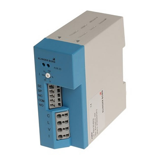
ASB20: Description of connections and function
Connection:
Control circuit:
Connector
SE
SP
NC
COM
NO
Load circle:
Connector
V
I
L
C
When connection it is essential to connect the release relay COM and NO in the control circuit of the
motor contactor!
The brake should not be used on a transformer. If the brake is used in conjunction with our soft starter,
it is essential to ensure the order of connections.
LED-display:
Display
Red LED glows at that for short time
Green LED glows
Green LED flashes
Red LED glows
Description
Motor connection for stand-still detection
Control signal for brake
Control output for special functions
Release relay COM (base point)
Control release
Description
Motor connection (see circuit diagram)
Mains supply
N for 230 V
L2 for 400 V
Input supply phase L3
Motor connection (see circuit diagram)
Description
Normal operation display
Stand-still or actuated motor
Normal operating mode
Motor brakes
Error indication through:
- Excessed braking time
- Disrupted power supply
- See failures
Page 1 of 2
Advertisement

Summary of Contents for Klinger Born ASB20
- Page 1 ASB20: Description of connections and function Connection: Control circuit: Connector Description Motor connection for stand-still detection Control signal for brake Control output for special functions Release relay COM (base point) Control release Load circle: Connector Description Motor connection (see circuit diagram)
- Page 2 Failures and corrective: If a fault occurs, the red LED lights up permanently and a new start is not possible. Fix the lock, by disconnecting the power supply for about 2 seconds. The cause of the disorder may be due to: Failures and cause Corrective The braking time is higher than 14...
Need help?
Do you have a question about the ASB20 and is the answer not in the manual?
Questions and answers