
Related Manuals for dSPACE DS1104

Summary of Contents for dSPACE DS1104
- Page 1 DS1104 R&D Controller Board Hardware Installation and Configuration For DS1104 and CP1104/CLP1104 Connector Panels Release 4.1 – March 2004...
- Page 2 It is available • On your dSPACE CD at \Diag\Tools\dSPACESupportWizard.exe • Via Start – Programs – dSPACE Tools (after installation of the dSPACE software) • At http://www.dspace.de/goto?supportwizard You can always find the latest version of dSPACE Support Wizard here. Software Updates and Patches dSPACE strongly recommends that you download and install the most recent patches for your current dSPACE installation.
-
Page 3: Table Of Contents
Installation and Configuration Overview ..........22 Checking the System Requirements..........24 Installing the Hardware How to Install the DS1104............... 26 Connecting a Connector Panel to the Board........28 How to Connect a Panel (CP, CLP) to a Board......29 How to Mount a Panel in a 19'' Rack..........30 Verifying the System How to Run ControlDesk..............32... - Page 4 Implementing Simulink Models Using Real-Time Interface... 44 How to Implement C Models............49 Handling Real-Time Applications ............. 50 Basics of Booting the DS1104............. 51 How to Handle Applications for the Global Memory ....53 How to Handle Applications for the Flash Memory ..... 55 How to Use Scoutcmd to Load and Start Applications ....
- Page 5 General Notes and Tips on Signal Conditioning ......146 Grounding and Shielding ............147 Avoiding Crosstalk ..............151 Wiring Up External Devices ............152 ADC Performance of dSPACE Boards ........153 Data Sheets DS1104 Data Sheet ..............158 CP1104 Data Sheet ..............161 CLP1104 Data Sheet..............
- Page 6 Contents DS1104 Hardware Installation and Configuration March 2004...
-
Page 7: Documentation Overview
For a brief description of this document, see About This Document on page 10. For more information on the documents that are available when you work with the DS1104 R&D Controller Board, see Related Documents on page 11. DS1104 Hardware Installation and Configuration... -
Page 8: Documentation Types
From each HelpDesk page, you can easily search and navigate to the desired information. You also have direct access to printable Adobe PDF files: see How to Work with dSPACE HelpDesk in the dSPACE HelpDesk. DS1104 Hardware Installation and Configuration... - Page 9 Implementation Experiment and Test Production Code Generation Calibration The topics that are shown depend on your dSPACE system. Context-sensitive help When you work with any dSPACE software, you can get context-sensitive help via the F1 key and/or Help button. PDF Files...
-
Page 10: About This Document
Documentation Overview About This Document This document will show you the installation of the DS1104 R&D Controller Board and CP1104/CLP1104 Connector Panels. It describes the hardware installation procedure, shows how to configure the system, and explains how to get started with your dSPACE system using an appropriate example. -
Page 11: Related Documents
RTI and RTI-MP Implementation Reference offers reference information on the various dialogs, files, options, etc. of Real-Time Interface (RTI and RTI-MP) for dSPACE systems. It also describes the blocks introduced by RTI-MP. DS1104 RTI Reference provides concise information on the board’s RTI library. - Page 12 MLIB/MTRACE. CLIB C Interface Library contains detailed reference information on the C Interface Library CLIB, which contains C functions to access the dSPACE processor and controller boards from the host PC. DS1104 Hardware Installation and Configuration March 2004...
-
Page 13: Introduction To The Ds1104
Introduction to the DS1104 The dSPACE system based on the DS1104 R&D Controller Board comprises hardware and software. For a short introduction to the hardware components of the DS1104, refer to Hardware on page 14. For information on the software, refer to Software on page 16. -
Page 14: Hardware
Hardware The DS1104 R&D Controller Board is a standard board that can be plugged into a PCI slot of a PC. The DS1104 is specifically designed for the development of high-speed multivariable digital controllers and real-time simulations in various fields. It is a complete real-time control system based on a 603 PowerPC floating-point processor running at 250 MHz. - Page 15 Introduction to the DS1104 Shipment The DS1104 R&D Controller Board is a single-board system. The hardware package contains: One PCI-slot board with a bracket including a 100-pin I/O connector. One adapter cable with two 50-pin female Sub-D connectors. The adapter cable is optional.
-
Page 16: Software
Introduction to the DS1104 Software The dSPACE software, such as the implementation and the experiment software, comes on CD-ROM and has to be installed first. For information on the software package, the installation and license handling, refer to Introduction to dSPACE Software in the dSPACE Software Installation and Management Guide. -
Page 17: Safety Precautions
Safety Precautions To avoid risk of injury and/or damage to the dSPACE hardware, read and ensure that you comply with the following safety precautions. Safety Precautions for Installing and Connecting the Hardware on page 18 Safety Precautions for Using Connector Panels on page 19... -
Page 18: Safety Precautions For Installing And Connecting The Hardware
Read the instructions carefully before starting installation. Note all warnings given. Handling boards dSPACE boards contain sensitive electronic devices. Before unpacking, installing and removing them, take the following precautions to avoid damage caused by high electrostatic voltage: Make sure that you and all material the board comes in contact with are properly grounded. -
Page 19: Safety Precautions For Using Connector Panels
Do not apply voltages/currents outside the specified ranges to the connector pins. Do not connect or disconnect any devices while the dSPACE System is powered up and/or external devices are switched on. Make sure that the PC and external devices are turned off beforehand. - Page 20 Safety Precautions DS1104 Hardware Installation and Configuration March 2004...
-
Page 21: Before You Start
Before You Start Before you start: Make yourself familiar with the installation and configuration procedures of the DS1104 R&D Controller Board. Refer to Installation and Configuration Overview on page 22. Check if your system fulfills the system requirements. Refer to Checking the System Requirements on page 24. -
Page 22: Installation And Configuration Overview
Read the instructions carefully before starting installation. Consider all warnings given. Installation sequence Installing the DS1104 requires the following steps in the specified order. 1. Check whether the software has been installed on the host PC. You must first install the software before installing any hardware component in the host PC. - Page 23 • On your dSPACE CD at \Diag\Tools\dSPACESupportWizard.exe • Via Start – Programs – dSPACE Tools (after installation of the dSPACE software) External devices For information on connecting external devices of your application to the dSPACE system, refer to Connecting External Devices to the dSPACE System on page 71.
-
Page 24: Checking The System Requirements
For details, refer to Checking the System Requirements in the dSPACE Software Installation and Management Guide. It is not possible to install the DS1104 in an expansion box. DS1104 Hardware Installation and Configuration March 2004... -
Page 25: Installing The Hardware
Installing the Hardware The DS1104 must be installed in the host PC. For detailed instructions refer to How to Install the DS1104 on page 26. If you use a connector panel for connecting the external devices to the dSPACE system, refer to Connecting a Connector Panel to the Board on page 28. -
Page 26: How To Install The Ds1104
Working with more than one dSPACE board in plug & play configuration may cause assignment problems. For details, refer to Problems with Multiple Plug & Play Boards on page 165. You can install as many DS1104 boards as free PCI slots are available in your host PC. Preconditions The host PC is switched off. - Page 27 If the PC does not boot, switch off the power supply immediately and check that the board is inserted firmly. For information on connecting external devices to the I/O connector of the DS1104, see How to Connect External Devices to a Board on page 72. DS1104 Hardware Installation and Configuration...
-
Page 28: Connecting A Connector Panel To The Board
19’’ industry rack. For instructions, refer to How to Mount a Panel in a 19'' Rack on page 30. For the connector pinouts of CP1104/ CLP1104, refer to CP1104/CLP1104 Connectors on page 88 DS1104 Hardware Installation and Configuration March 2004... -
Page 29: How To Connect A Panel (Cp, Clp) To A Board
1 If the panel is to be mounted in a 19” rack, this should be done first (see How to Mount a Panel in a 19'' Rack on page 30). 2 Plug the CP1104 or CLP1104 to the DS1104 and tighten the lock screws. Take care not to mix up the connectors of the DS1104. -
Page 30: How To Mount A Panel In A 19'' Rack
Depending on the rack used, several M2.5x10 or M3x10 bolts are required. Panel is attached by M2.5x10 or M3x10 bolts 122.5 mm 128.5 mm (4.82 inch) (5.06 inch) M2.5 or M3 threads Panel 5 mm (0.2 inch) spacing DS1104 Hardware Installation and Configuration March 2004... -
Page 31: Verifying The System
Verifying the System After the DS1104 R&D Controller Board is installed (see How to Install the DS1104 on page 26), no further configuration is necessary. Nevertheless you should check if your board is ready to run real-time applications. Running ControlDesk The dSPACE real-time hardware is managed by the Platform Manager integrated in ControlDesk. -
Page 32: How To Run Controldesk
After installing the dSPACE software, ControlDesk is available in the Windows Start menu and as an icon on the desktop. To start ControlDesk 1 In the Windows Start menu, choose Programs – dSPACE Tools – ControlDesk. 2 In the Navigator, click the Platform tab. - Page 33 Verifying the System With the Platform Navigator, it is possible: to register other dSPACE boards in your system that do not support plug & play. to download applications to your simulation platform manually. For more information on ControlDesk and its features, refer to the ControlDesk Experiment Guide.
-
Page 34: How To View The Board Properties
Properties After installation, the board properties can be checked. To view the board properties 1 In the Platform Navigator, double-click the corresponding DS1104 icon to open the Controller Board Properties dialog. 2 In the Controller Board Properties dialog, check the accompanying pages. - Page 35 - of the platforms already registered, in the form of key-value pairs. Initializing a DS1104 some properties of the board are entered into the dSPACE.ini file. If you delete this file, you will have to reregister any boards that do not support plug &...
- Page 36 Verifying the System To view the dSPACE.ini file From ControlDesk’s menu bar, choose View – dSPACE.ini. The Dspace.ini window opens. DS1104 Hardware Installation and Configuration March 2004...
-
Page 37: How To Verify The Installation
To verify the installation 1 In ControlDesk’s File Selector, change to %DSPACE_ROOT%\Demos\DS1104\Check\, select the System Description file (SDF), and drag & drop it onto the DS1104 icon in the Platform Navigator. 2 In the Tool Window, select the Log Viewer page. -
Page 38: Updating The Firmware
Verifying the System Updating the Firmware Usually your DS1104 board contains the latest firmware. If you install a new dSPACE Release it may contain newer firmware. In this case the firmware can be updated. After you install the dSPACE Release, you can update the firmware. - Page 39 Based on dSPACE version field in the Current Firmware frame of the Firmware Management dialog. In these cases, you have to update the firmware.
-
Page 40: How To Update The Firmware
5 When the update is complete, the Close button on the Firmware Management dialog is enabled. Click it to close the dialog. You have to update the firmware for each firmware type individually. DS1104 Hardware Installation and Configuration March 2004... -
Page 41: Implementing And Handling Applications
Implementing Models on page 43. 2. Then build your model and download it to your dSPACE real-time hardware. For detailed instructions on how to download, start and stop an application, see Handling Real-Time Applications on page 50. - Page 42 ControlDesk to experiment with it. For some basic information on how to create a ControlDesk experiment and observe the variables and change parameters of a running real-time application, see Experimenting with ControlDesk on page 59. DS1104 Hardware Installation and Configuration March 2004...
-
Page 43: Implementing Models
An algorithm can also be handcoded in C. In addition to the necessary compilers, the tools required to generate object files are part of the dSPACE software. See How to Implement C Models on page 49. DS1104 Hardware Installation and Configuration... -
Page 44: Implementing Simulink Models Using Real-Time Interface
Installation and Management Guide. 2 Open ControlDesk (via Programs – dSPACE Tools – ControlDesk in the Windows Start menu) and specify the DS1104 as the working board (via Platform – Set Working Board from the menu bar). For details, see How to Set the Working Board in the ControlDesk Experiment Guide. - Page 45 The Simulink Library Browser appears in a separate window. 6 In the Simulink Library Browser window, you can click the +/– signs to browse through the dSPACE RTI1104 library. You can also right-click a library icon and choose from the context menu Open the <Name of the Library>...
- Page 46 To open a dSPACE board library from the MATLAB prompt In the MATLAB Command Window, enter rti1104. The dSPACE board library for the DS1104 is displayed. The DS1104 board library contains information, demos and the icons available with the DS1104. Double-click the items to obtain more information.
- Page 47 The Simulink model smd_1104_sl is displayed in an extra window. 3 To examine the model, double-click its blocks. 4 From the menu bar of the Model window, choose Tools – Real-Time Workshop – Options to view the simulation parameters. DS1104 Hardware Installation and Configuration March 2004...
- Page 48 Refer to Experimenting with ControlDesk on page 59. If the real-time application - stored in the current MATLAB working folder - is stopped, it can be downloaded to the DS1104 again using the SDF file in ControlDesk. A new build process is not needed if you do not change the Simulink model in the meantime.
-
Page 49: How To Implement C Models
The object file smd_1104_hc.ppc is generated, downloaded and started. 4 Use ControlDesk to stop the real-time application: Select the DS1104 in the Platform Navigator, and click the Stop RTP/Simulation icon in the Platform toolbar. DS1104 Hardware Installation and Configuration March 2004... -
Page 50: Handling Real-Time Applications
Basics of Booting the DS1104 on page 51. Global and flash On the DS1104, the application can be loaded to the global memory memory or flash memory. For instructions on how to start, stop and reload... -
Page 51: Basics Of Booting The Ds1104
Clearing an application on page 57). Warm boot/reload If the DS1104 is in the idle state after power-up or if an executing application has been stopped by ControlDesk, you can start a new application by loading it to the global or flash memory. If you load an application to the flash memory, it is copied to the global memory before it is started. - Page 52 To avoid problems with undefined termination values, use RTI’s simulation control (RUN/STOP mechanism) for stopping and reloading applications (see Simulation Control (RUN/STOP Mechanism) in the RTI and RTI-MP Implementation Guide). DS1104 Hardware Installation and Configuration March 2004...
-
Page 53: How To Handle Applications For The Global Memory
Or you can choose Platform – Application – Load Application from the menu bar. If you drag & drop an application onto the processor board when your system is still running, a dialog similar to the following opens. DS1104 Hardware Installation and Configuration March 2004... - Page 54 2 From the menu bar, choose Platform – Application – Reload Application. Or you can click the Reload Application/Start Simulation icon in the Platform toolbar. The application that was previously downloaded to the global memory is loaded again and started. DS1104 Hardware Installation and Configuration March 2004...
-
Page 55: How To Handle Applications For The Flash Memory
If you load an application when your system is still running, a dialog similar to the following opens. If you confirm the message with Yes, the running application is stopped before the new application is downloaded and started. DS1104 Hardware Installation and Configuration March 2004... - Page 56 Or you can click the Reload Application/Start Simulation icon in the Platform toolbar. The application that was previously downloaded to the flash is copied to the global memory again. Then, the application is started automatically. DS1104 Hardware Installation and Configuration March 2004...
- Page 57 Clear flash application memory to delete only the loaded application from the flash memory. The currently loaded application is displayed in the Application in Flash field. 5 Click Clear Memory to clear the flash memory according to your selection. DS1104 Hardware Installation and Configuration March 2004...
-
Page 58: How To Use Scoutcmd To Load And Start Applications
The test.sdf application is loaded to the board, and the RTP is started. To load an application to the flash memory using scoutcmd In a DOS window, enter scoutcmd -b ds1104 test.sdf -fl The test.sdf application is loaded to the flash memory (parameter -fl), and the RTP is started. -
Page 59: Experimenting With Controldesk
Implementing and Handling Applications Experimenting with ControlDesk To observe the behavior of the real-time application and to change application-specific parameters, use dSPACE’s experimentation tool ControlDesk. For detailed information on ControlDesk and its features, refer to the ControlDesk Experiment Guide. Required files To experiment with a real-time application, three application-specific files are required: see How to Generate the Required Files on page 60. -
Page 60: How To Generate The Required Files
For information on how to write your own TRC file, refer to Syntax of the TRC File in the ControlDesk Reference. To create and edit an SDF file, you can use ControlDesk’s SDF File Editor or the Save Current Configuration command. DS1104 Hardware Installation and Configuration March 2004... -
Page 61: How To Use Controldesk
DS1104 as the working board: In the Platform Navigator, you can recognize the working board by its bold print. If the DS1104 is not the current working board, choose Platform – Set Working Board …... - Page 62 Implementing and Handling Applications 4 In the Variable Browser, click the trace group Model to display the variables (a, v, x, f, ...) of that block in the Showlist on the right. DS1104 Hardware Installation and Configuration March 2004...
- Page 63 (for example, Data Acquisition). • In the Instrument Selector, click the icon of the instrument (for example, a PlotterArray). • In the layout window, draw a rectangle using the mouse. DS1104 Hardware Installation and Configuration March 2004...
- Page 64 (for example, x). The red frame disappears when the connection is built. 7 Select the instrument, and choose Properties from the context menu to display or change the properties of the instrument. DS1104 Hardware Installation and Configuration March 2004...
- Page 65 ControlDesk instrument. To save data connections, you should create an experiment and add the layout to it. For further information, refer to Saving and Loading Instrument Panels in the ControlDesk Experiment Guide. DS1104 Hardware Installation and Configuration March 2004...
- Page 66 ControlDesk will open the experiment together with all the related files. 3 Use the Platform Navigator to load the file smd_1104_hc.sdf from the same folder. 4 Close all windows except the instrument panel DS1104 Spring-Mass-Damper Demo (SMD). DS1104 Hardware Installation and Configuration March 2004...
- Page 67 Implementing and Handling Applications 5 From the menu bar, choose Instrumentation – Animation mode to start the animation. DS1104 Hardware Installation and Configuration March 2004...
- Page 68 Implementing and Handling Applications 6 Change the parameter Mass m to 0.10 with the slider, and observe the system behavior in the plotter. DS1104 Hardware Installation and Configuration March 2004...
- Page 69 7 Change the Frequency f to 100.0 with the slider, and observe the system behavior in the plotter without stopping the Animation mode. For more information on ControlDesk and its features, refer to the ControlDesk Experiment Guide. DS1104 Hardware Installation and Configuration March 2004...
- Page 70 Implementing and Handling Applications DS1104 Hardware Installation and Configuration March 2004...
-
Page 71: Connecting External Devices To The Dspace System
How to Connect External Devices to a Board on page 72 How to Connect External Devices to a Connector Panel on page 74 DS1104 Hardware Installation and Configuration March 2004... -
Page 72: How To Connect External Devices To A Board
Do not apply voltages/currents outside the specified ranges to the connector pins. 4 Connect the devices belonging to your application to the DS1104 via the adapter cable. Do not mix up the connectors of the adapter cable. They are labeled P1A, P1B. - Page 73 Connecting External Devices to the dSPACE System 6 Turn on the host PC. The host PC should boot as usual. 7 Turn on all external devices connected to the dSPACE system. DS1104 Hardware Installation and Configuration March 2004...
-
Page 74: How To Connect External Devices To A Connector Panel
5 Reconnect the host PC and all external devices to the power supply. 6 Turn on the host PC. The host PC should boot as usual. 7 Turn on all external devices connected to the dSPACE system. DS1104 Hardware Installation and Configuration March 2004... -
Page 75: Uninstalling The System
Uninstalling the System All components of a dSPACE system, software and hardware, can be removed from the host PC in the following order: 1. You have to remove the software first. For further information, refer to Removing dSPACE Software in the dSPACE Software Installation and Management Guide. -
Page 76: How To Remove The Hardware
For details, refer to Safety Precautions for Installing and Connecting the Hardware on page 18. Method To remove the dSPACE board from the host PC WARNING! Hazardous voltages. Risk of electric shock and/or damage to the hardware. Before removing any board, make sure that: The power supply of the host PC is switched off. -
Page 77: Connector Pinouts And Leds
Board Overview on page 78 contains an illustration of the board, showing the location of connectors, jumpers and LEDs. DS1104 Connectors on page 80 shows the pin assignments of the different board connectors. CP1104/CLP1104 Connectors on page 88 shows the front view of the connector panel and the pin assignments of the connectors equipped on the panel. -
Page 78: Board Overview
Slave DSP debug connector (P3) Status LED Slave DSP flash jumper (J1) The DS1104 contains the following important elements (from left to right): The I/O connector (P1) is a 100-pin connector. The signals available at this connector are described in I/O Connector (P1) on page 81. - Page 79 Flash Jumper (J1) on page 87. The red status LED is equipped for troubleshooting purposes. For details, see Checking the DS1104 on page 164. The master PPC debug connector (P2) is a JTAG 1149.1 hardware debug connector and can be used for master PPC debugging.
-
Page 80: Ds1104 Connectors
Slave DSP Flash Jumper (J1) on page 87 Prior to connecting external devices to the board, ensure you have familiarized yourself with the relevant instructions provided in Connecting External Devices to the dSPACE System on page 71. DS1104 Hardware Installation and Configuration March 2004... -
Page 81: I/O Connector (P1)
I/O lines terminating at the I/O connector, see Signal Connection to External Devices on page 119. For the DS1104, the total load of the connector pins providing VCC (P1 19 and P1 20; P1A 4 and P1B 4 on the Sub-D connectors) must not exceed 500 mA. - Page 82 P1B 49 P1 94 P1A 49 P1 95 P1B 33 ADCH4 P1 96 P1A 33 ADCH3 P1 97 P1B 17 P1 98 P1A 17 P1 99 P1B 50 ADCH2 P1 100 P1A 50 ADCH1 DS1104 Hardware Installation and Configuration March 2004...
- Page 83 TXD (TXD) SCAP3 SCAP4 SCAP2 VCC (+5 V) SCAP1 SPWM6 SPWM4 SPWM5 SPWM3 SPWM1 SPWM2 IDX(1) IDX(1) PHI90(1) PHI0(1) PHI90(1) PHI0(1) IO18 IO16 IO12 IO14 IO10 DACH7 DACH5 DACH3 DACH1 ADCH7 ADCH5 ADCH3 ADCH1 DS1104 Hardware Installation and Configuration March 2004...
- Page 84 RXD (RXD) SSIMO SSOMI SSTE VCC (+5 V) SSCLK ST3PWM ST1PWM ST2PWM SPWM9 SPWM7 SPWM8 IDX(2) IDX(2) PHI90(2) PHI0(2) PHI90(2) PHI0(2) IO19 IO17 IO13 IO15 IO11 DACH8 DACH6 DACH4 DACH2 ADCH8 ADCH6 ADCH4 ADCH2 DS1104 Hardware Installation and Configuration March 2004...
-
Page 85: Master Ppc Debug Connector (P2)
For the location of the connector on the board, see Board Overview on page 78. Connector (P2) Signal Signal TRST RUN_STP VDD_SENSE CHKSTP_IN HRESET CKSTP_OUT The dSPACE software does not support the master PPC debug connector. DS1104 Hardware Installation and Configuration March 2004... -
Page 86: Slave Dsp Debug Connector (P3)
The TMS320F240 slave DSP features a superset of the IEEE 1149.1 JTAG standard emulation port. This emulation port can be used for software debugging. The DS1104 contains a JTAG connector to connect an external emulator such as the Texas Instruments XDS510. -
Page 87: Slave Dsp Flash Jumper (J1)
• the watchdog is enabled VCCp The dSPACE software does not support the watchdog of the slave DSP. For this reason, do not change the jumper’s default setting shown above. DS1104 Hardware Installation and Configuration... -
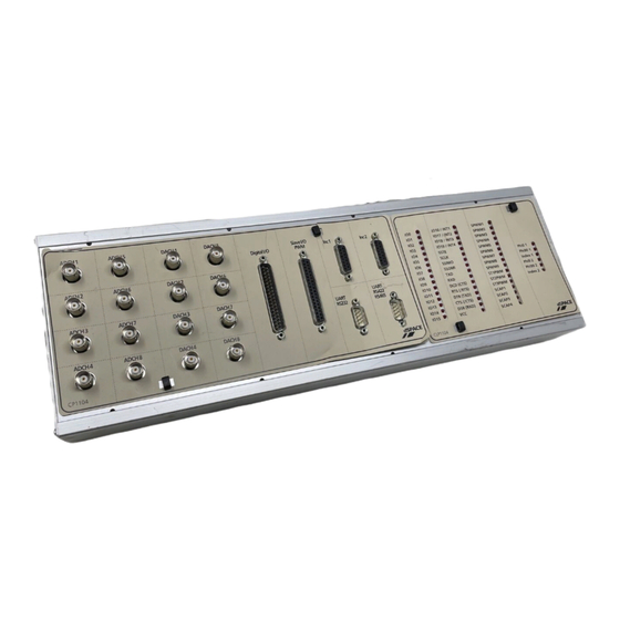
Page 88: Cp1104/Clp1104 Connectors
Connector Pinouts and LEDs CP1104/CLP1104 Connectors The connector panels CP1104 and CLP1104 provide easy-to-use connections between the DS1104 and devices to be connected to it. Devices can be individually connected, disconnected or interchanged without soldering. This simplifies system construction, testing and troubleshooting. - Page 89 PC power supply must not exceed 500 mA (CP1104) or 400 mA (CLP1104). The VCC lines are protected against short circuits by a common multifuse on the DS1104. DS1104 Hardware Installation and Configuration March 2004...
- Page 90 Connector Pinouts and LEDs If VCC is overloaded or shorted, the multifuse on the DS1104 is heated up by the overcurrent and abruptly raises its resistance. To reset the multifuse to its initial low resistance, turn off the power for some minutes to allow the multifuse to cool down.
-
Page 91: Bnc Connectors (Cp1
BNC wiring. For detailed information (I/O circuits, electrical characteristics, etc.) on the I/O lines terminating at the BNC connectors, see Analog Inputs on page 120 and Analog Outputs on page 122. DS1104 Hardware Installation and Configuration March 2004... -
Page 92: Digital I/O Connector (Cp17)
(front view). Do not rely on the numbers written on Sub-D connectors. Connector (CP17) Signal Signal VCC (+5 V) VCC (+5 V) IO19 IO17 IO18 IO16 IO15 IO13 IO14 IO12 IO11 IO10 DS1104 Hardware Installation and Configuration March 2004... - Page 93 PC power supply must not exceed 500 mA (CP1104) or 400 mA (CLP1104). For detailed information (I/O circuits, electrical characteristics, etc.) on the I/O lines terminating at this connector, see Bit I/O on page 125. DS1104 Hardware Installation and Configuration March 2004...
-
Page 94: Slave I/O Pwm Connector (Cp18)
Do not rely on the numbers written on Sub-D connectors. Connector (CP18) Signal Signal SCAP1 SCAP3 SCAP2 SCAP4 ST2PWM ST1PWM ST3PWM SPWM1 SPWM3 SPWM2 SPWM5 SPWM4 SPWM7 SPWM6 SPWM9 SPWM8 SSIMO SSOMI SCLK SSTE VCC (+5 V) VCC (+5 V) DS1104 Hardware Installation and Configuration March 2004... - Page 95 PC power supply must not exceed 500 mA (CP1104) or 400 mA (CLP1104). For detailed information (I/O circuits, electrical characteristics, etc.) on the I/O lines terminating at this connector, see Slave DSP Digital I/O on page 142. DS1104 Hardware Installation and Configuration March 2004...
-
Page 96: Incremental Encoder Interface Connectors (Cp19, Cp20)
CP20 (x = 2). For the CP1104 and CLP1104 Connector Panels, the total load of all connector pins that provide access to the PC power supply must not exceed 500 mA (CP1104) or 400 mA (CLP1104). DS1104 Hardware Installation and Configuration March 2004... - Page 97 Connector Pinouts and LEDs For detailed information (I/O circuits, electrical characteristics, etc.) on the I/O lines terminating at this connector, see Incremental Encoder Interface on page 129. DS1104 Hardware Installation and Configuration March 2004...
-
Page 98: Uart Rs232 Connector (Cp21)
The pinout has been adapted from the 9-pin RS232 connector of a PC. The DS1104 supports one serial interface. In RS232 mode the signals are available from the RS232 connector CP21. In RS422/485 mode the signals are available from the RS422/485 connector CP22. -
Page 99: Uart Rs422/Rs485 Connector (Cp22)
The UART RS422/RS485 connector CP22 is a 9-pin, male Sub-D connector located on the front of the connector panel. The DS1104 supports one serial interface. In RS232 mode the signals are available from the RS232 connector CP21. In RS422/485 mode the signals are available from the RS422/485 connector CP22. -
Page 100: Clp1104 Led Assignments
The pulse length of data signals of the UART (RXD, TXD) is extended to make even small blocks of data visible. The power required by the LEDs is taken from the DS1104’s supply voltage (VCC). DS1104 Hardware Installation and Configuration... -
Page 101: Mapping Of I/O Signals
Mapping of I/O Signals The following table lists the I/O signals of the DS1104 by function groups, their electrical specifications, and the mapping of these signals to RTI blocks and RTLib functions. The table also provides the mapping of the I/O signals to the I/O pins on the DS1104, on the Sub-D connectors (P1A, P1B), and on the CP1104/CLP1104 connector panels. - Page 102 Mapping of I/O Signals Conflicting I/O features Some I/O features of the DS1104 conflict with other I/O features. In the table below, these signals are marked with an asterisk“*“. For an overview, see Conflicting I/O Features on page 109. Channel/Bit Numbers of Related RTI Blocks/RTLib Functions I/O Pin on …...
- Page 103 • Output current range: ±5 mA • I/O circuit and further electrical characteristics: see Bit I/O on page 125 DS1104BIT_IN_Cx / Bit 0 See Bit I/O Unit in the DS1104 Bit 0 P1 68 P1A 12 CP17 20 DS1104BIT_OUT_Cx RTLib Reference...
- Page 104 DS1104SER_INT_REC_LEV RXD * P1 7 P1B 2 CP22 3 TXD * P1 8 P1A 2 CP22 2 RXD * P1 9 P1B 35 CP22 4 TXD * P1 10 P1A 35 CP22 1 DS1104 Hardware Installation and Configuration March 2004...
- Page 105 P1B 36 CP18 35 bit 1 SSIMO * Bit 12 Group 4 P1 13 P1B 3 CP18 16 bit 2 SSOMI * Bit 13 Group 4 P1 11 P1B 19 CP18 34 bit 3 DS1104 Hardware Installation and Configuration March 2004...
- Page 106 P1 28 P1A 38 CP18 8 Slave DSP PWMSV Generation SPWM5 * Phase 3 Phase 3 P1 24 P1A 21 CP18 9 in the DS1104 RTLib Reference SPWM2 Phase 1 Phase 1 P1 30 P1A 22 CP18 26 (inverted) (inverted) SPWM4...
- Page 107 1, 4, 6, 12 … 15, 20, 25, 30 … 33, 36, 37 Incremental Encoder Interface CP19, CP20 8, 10 … 15 UART RS232 and RS485/422 CP21 , CP22 GND of the DS1104 is internally connected to PC ground. DS1104 Hardware Installation and Configuration March 2004...
- Page 108 18, 19 Incremental Encoder Interface CP19, CP20 1, 9 For the DS1104, the total load of the connector pins P1 19 and P1 20 (pins P1B 4 and P1A 4 on the Sub-D connector) must not exceed 500 mA. For the connector panels CP1104 and CLP1104, the total load of all connector pins that provide access to the PC power supply must not exceed 500 mA (CP1104) or 400 mA (CLP1104).
-
Page 109: Conflicting I/O Features
I/O feature as a whole. Suppose two I/O features of the dSPACE board use the same on-board timer device. In this case, only one of the two I/O features can be used at a time. - Page 110 Mapping of I/O Signals Conflicts for the Bit I/O Unit The following I/O features of the DS1104 conflict with the Bit I/O unit: Bit I/O Unit *) Conflicting I/O Feature **) (RTI) (RTLib) Signal (RTI) (RTLib) Conflicts Concerning Single Bits...
- Page 111 Mapping of I/O Signals Conflicts for the Slave DSP Bit I/O Unit The following I/O features of the DS1104 conflict with the Slave DSP Bit I/O unit: Slave DSP Bit I/O Unit *) Conflicting I/O Feature **) (RTI) (RTLib) Signal...
- Page 112 Mapping of I/O Signals Conflicts for Slave DSP 1-Phase PWM Signal Generation (PWM) The following I/O features of the DS1104 conflict with Slave DSP 1-Phase PWM Signal Generation: Slave DSP 1-Phase PWM Signal Generation (PWM) *) Conflicting I/O Feature **)
- Page 113 Mapping of I/O Signals Conflicts for Slave DSP Space Vector PWM Signal Generation (PWMSV) The following I/O features of the DS1104 conflict with Slave DSP Space Vector PWM Signal Generation: Slave DSP Space Vector PWM Signal Generation (PWMSV) *) Conflicting I/O Feature **)
- Page 114 Mapping of I/O Signals Conflicts for Slave DSP Square-Wave Signal Generation (D2F) The following I/O features of the DS1104 conflict with Slave DSP Square-Wave Signal Generation: Slave DSP Square-Wave Signal Generation (D2F) *) Conflicting I/O Feature **) (RTI) (RTLib) Signal...
- Page 115 Mapping of I/O Signals Conflicts for Slave DSP PWM Signal Measurement (PWM2D) The following I/O features of the DS1104 conflict with Slave DSP PWM Signal Measurement: Slave DSP PWM Signal Measurement (PWM2D) *) Conflicting I/O Feature **) (RTI) (RTLib) Signal...
- Page 116 Mapping of I/O Signals Conflicts for Slave DSP Square-Wave Signal Measurement (F2D) The following I/O features of the DS1104 conflict with Slave DSP Square-Wave Signal Measurement: Slave DSP Square-Wave Signal Measurement (F2D) *) Conflicting I/O Feature **) (RTI) (RTLib) Signal...
- Page 117 • See Slave DSP Serial • Related RTI blocks: DS1104SL_DSP_BIT_IN_Cx/ Peripheral Interface in the DS1104SL_DSP_BIT_OUT_Cx DS1104 RTLib Reference • Related RTLib functions: see Slave DSP Bit I/O Unit in the DS1104 RTLib Reference DS1104 Hardware Installation and Configuration March 2004...
- Page 118 Mapping of I/O Signals DS1104 Hardware Installation and Configuration March 2004...
-
Page 119: Signal Connection To External Devices
Serial Interface on page 136 Slave DSP Digital I/O on page 142 User interrupts must be connected to the pins of the bit I/O unit. For details, see Recognizing User Interrupts on page 128. DS1104 Hardware Installation and Configuration March 2004... -
Page 120: Analog Inputs
ADCH1 ... ADCH4 Four 12-bit parallel ADCs with one input signal each: ADCH5 ... ADCH8 For a feature description of the ADCs refer to ADC Unit in the DS1104 Features document. For detailed information on connecting external devices to the analog... -
Page 121: Input Circuit And Electrical Characteristics
Noise, crosstalk and inductive effects can degrade the signal and lead to incorrect results if you do not perform the following correctly: Grounding and Shielding on page 147 Avoiding Crosstalk on page 151 Wiring Up External Devices on page 152 DS1104 Hardware Installation and Configuration March 2004... -
Page 122: Analog Outputs
The DS1104 provides a digital/analog converter (DAC) with 8 parallel DAC channels. The analog output channels are called DACH1 ... DACH8. For a feature description of the DACs refer to DAC Unit in the DS1104 Features document. For detailed information on connecting external devices to the analog... -
Page 123: Output Circuit And Electrical Characteristics
Value Min. Max. Output voltage –10 V +10 V Output current –5 mA +5 mA → 0 Ω Output resistance Power-up default SNR (signal-to-noise ratio) > 80 dB DAC outputs are low-impedance outputs. DS1104 Hardware Installation and Configuration March 2004... -
Page 124: Notes And Tips On Signal Conditioning
Noise, crosstalk and inductive effects can degrade the signal and lead to incorrect results if you do not perform the following correctly: Grounding and Shielding on page 147 Avoiding Crosstalk on page 151 Wiring Up External Devices on page 152 DS1104 Hardware Installation and Configuration March 2004... -
Page 125: Bit I/O
Signal Connection to External Devices Bit I/O The DS1104 contains a bit I/O unit with 20 digital I/O pins called IO0 ... IO19. You can select the direction for each bit individually by software. For a feature description of the bit I/O unit refer to Bit I/O Unit in the DS1104 Features document. -
Page 126: I/O Circuit And Electrical Characteristics
500 µA Input current (The current direction is shown in the circuit diagram above.) Power-up default All bit I/O output circuits are disabled and driven to VCC by the built-in 10 kΩ pull-up resistors. DS1104 Hardware Installation and Configuration March 2004... -
Page 127: Notes And Tips On Signal Conditioning
• Grounding and Shielding on page 147 • Avoiding Crosstalk on page 151 • Wiring Up External Devices on page 152 DS1104 Hardware Installation and Configuration March 2004... - Page 128 The signal must remain low for at least 100 ns after the transition. high : 1 µs high high min : 100 ns low min DS1104 Hardware Installation and Configuration March 2004...
-
Page 129: Incremental Encoder Interface
Signal Connection to External Devices Incremental Encoder Interface The DS1104 provides a digital incremental encoder interface with input channels for two incremental encoders. The pins which make up the inputs are called: IDX(1), IDX(1), PHI90(1), PHI90(1), PHI0(1), PHI0(1) IDX(2), IDX(2), PHI90(2), PHI90(2), PHI0(2), PHI0(2) The incremental encoder interface supports single-ended TTL and differential RS422 signals (selectable by software). -
Page 130: Input Circuit And Electrical Characteristics
0 ... 5 V. RS422 input resistance The input resistance gradually drops from 8.5 kΩ at the corner frequency of 28 kHz to 210 Ω at the corner frequency of 225 kHz. DS1104 Hardware Installation and Configuration March 2004... - Page 131 Signal Connection to External Devices Encoder power The DS1104 offers a 5 V supply voltage for the incremental encoders. supply lines These voltage outputs (VCC) are connected to the PC‘s 5 V power supply via a multifuse. If a supply output is overloaded or shorted, the multifuse is heated by the overcurrent and abruptly increases its resistance.
-
Page 132: Notes And Tips On Signal Conditioning
1 µs. The interrupt is activated by the low to high transition of the signal. The signal must remain high for at least 100 ns after the transition from low to high. high : 100 ns high high min : 1 µs low min DS1104 Hardware Installation and Configuration March 2004... - Page 133 To allow proper operation, do not connect the outputs of your encoder to an AC-coupling network. The input signals must be DC signals. Encoder providing Connect encoders that provide differential RS422 signals to the differential RS422 DS1104 as shown in the illustration below. signals DS1104 Incremental encoder output PHI0...
- Page 134 If your encoder has sense lines, connect SENSE+ to Vsupply and SENSE lines SENSE– to GND. Connect the sense lines directly within the connector of the encoder (see below). DS1104 Incremental encoder output VSupply SENSE + SENSE - DS1104 Hardware Installation and Configuration March 2004...
- Page 135 If you use an external supply voltage, you have: power supply To guarantee that no input voltages are fed to the DS1104 while it is switched off To connect the encoder’s ground line to a ground pin of the board...
-
Page 136: Serial Interface
TXD, TXD RTS, RTS CTS, CTS DCD, DTR, DSR For a feature description refer to Serial Interface in the DS1104 Features document. For notes and tips of connecting the UART, refer to: Connecting RS232 Devices on page 137 Connecting RS422/RS485 Devices on page 138... -
Page 137: Connecting Rs232 Devices
DS1104 For some devices (e.g., modems), you should not cross-connect the TXD and RXD signals. For the correct connection refer to the manual of the device you want to connect to the DS1104. DS1104 Hardware Installation and Configuration March 2004... -
Page 138: Connecting Rs422/Rs485 Devices
Line termination The UART chip of the DS1104 does not provide line termination. If you use the UART as an RS422 or RS485 transceiver, line termination is essential, especially for faster data transfer rates and long cables. The main reasons for correct termination are reflections at the ends of the line, and the minimum transmitter load requirement. - Page 139 T = Transmitter R = Receiver The termination resistor Z , must be within 20% of the characteristic ) and can vary from 90 Ω to 120 Ω. impedance of the cable (Z DS1104 Hardware Installation and Configuration March 2004...
- Page 140 If no transmitter is currently active in an RS485 network, undefined conditions (RS485) conditions may occur. To avoid these conditions, you must provide a pull-up and a pull-down resistor (each 1 kΩ) as shown above. DS1104 Hardware Installation and Configuration March 2004...
- Page 141 The figure below shows the grounding arrangement in an RS485 network. Ground wire 100 Ω 100 Ω 100 Ω 100 Ω Logic ground Logic ground Chassis ground Chassis ground T = Transmitter R = Receiver DS1104 Hardware Installation and Configuration March 2004...
-
Page 142: Slave Dsp Digital I/O
Signal Connection to External Devices Slave DSP Digital I/O The slave DSP of the DS1104 provides the following I/O: Slave DSP Bit I/O Unit Slave DSP Timing I/O Unit Slave DSP Serial Peripheral Interface The pins of the slave DSP digital I/O are called: SPWM1 ... -
Page 143: I/O Circuit And Electrical Characteristics
500 µA Input current (The current direction is shown in the circuit diagram above.) Power-up default All digital I/O output circuits are disabled and driven to VCC by the built-in 10 kΩ pull-up resistors. DS1104 Hardware Installation and Configuration March 2004... -
Page 144: Notes And Tips On Signal Conditioning
If you want to change the power-up default, you can set the I/O pins to a defined logical low level by connecting a 1 kΩ pull-down resistor from ground to each I/O pin. DS1104 Hardware Installation and Configuration March 2004... - Page 145 Signal Connection to External Devices Using the ST1PWM Pin The ST1PWM pin is lead to the interrupt controller of the DS1104, so it is possible to generate interrupts that are synchronous to PWM signal generation. You can also use the pin as a further external interrupt input (user interrupt).
-
Page 146: General Notes And Tips On Signal Conditioning
ControlDesk. This may give the impression that the performance of the A/D sections of dSPACE boards is poor. For an explanation of this incorrect impression and further background information (definition of SNR, measuring noise), refer to ADC Performance of dSPACE Boards on page 153. -
Page 147: Grounding And Shielding
For notes on cabling and connecting ground lines as well as further background information, refer to Grounding Signals on page 149. Shielding For notes on cabling and connecting the shield as well as further background information, refer to Shielding on page 150. DS1104 Hardware Installation and Configuration March 2004... - Page 148 Shield is a barrier to keep in everything inside and keep out everything outside. It is usually connected to the device enclosures at both ends to form a closed cage around all signals and cards. It is not necessarily connected to power ground. DS1104 Hardware Installation and Configuration March 2004...
- Page 149 If not enough ground pins are available at the connector, several return lines can be attached to a common ground pin. However, this common ground lead should be kept as short as possible to reduce ground line inductance. DS1104 Hardware Installation and Configuration March 2004...
- Page 150 Using the encoder interface with differential signals, the PHI90 line should be twisted with PHI90, PHI0 with PHI0 et cetera. Connecting shield to Use a metal shell connector to the dSPACE board connector and the dSPACE system connect the shield to the connector shell so that shield, connector shell and system enclosure form a closed shield surrounding all electronics.
-
Page 151: Avoiding Crosstalk
Signal Connection to External Devices Do not connect the shield to the GND pins of the dSPACE system. Connecting shield to At the other end, the shield should be connected directly to the the external device sensor/actuator housing. Sometimes sensors and actuators have dedicated shield pins available at their connector. -
Page 152: Wiring Up External Devices
Connect your external devices to the board connectors directly. Using BNC cables If your dSPACE hardware offers BNC cables: If noise is a problem, avoid the use of BNC connectors. BNC connectors use the outside of the connector for ground. They do not permit shielding. -
Page 153: Adc Performance Of Dspace Boards
16-bit ADC, for example, never has an effective number of bits equal to 16. The A/D section of every dSPACE board is FFT (Fast Fourier Transform) tested during production so that we can guarantee the published data sheet values for every board. For 16-bit ADCs we typically achieve an SNR of 78 …... - Page 154 (occasional extreme peaks must be ignored using this equation). Furthermore, the peak-to peak noise theoretically might be ±10 V (even if the inputs are shorted) without decreasing the SNR, assuming that such high peaks appear rarely enough. DS1104 Hardware Installation and Configuration March 2004...
- Page 155 “voltage range” for the dSPACE system! dSPACE boards have an input range of ±10 V and you are looking at signals with a voltage range of a few mV. That is similar to using a ruler to measure 1/1,000 inches.
- Page 156 Signal Connection to External Devices DS1104 Hardware Installation and Configuration March 2004...
-
Page 157: Data Sheets
Data Sheets For the technical data of the DS1104 and the optional connector panels CP1104/CLP1104, see: DS1104 Data Sheet on page 158 CP1104 Data Sheet on page 161 CLP1104 Data Sheet on page 161 DS1104 Hardware Installation and Configuration March 2004... -
Page 158: Ds1104 Data Sheet
±10 V input voltage range 2 µs conversion time • • ±5 mV offset error • ±0.25 % gain error • 4 ppm/K offset drift • 25 ppm/K gain drift • >80 dB signal-to-noise ratio (SNR) DS1104 Hardware Installation and Configuration March 2004... - Page 159 5 V/0.5 A sensor supply voltage Serial interface • 1 serial UART (universal asynchronous receiver and transmitter) • Selectable transceiver mode: RS232/RS422/RS485 • Max. baudrate RS232: 115.2 kBaud • Max. baudrate RS422/RS485: 1 MBaud DS1104 Hardware Installation and Configuration March 2004...
- Page 160 0 … 55 ºC (32 ... 131 ºF) Cooling Active cooling by fan Power supply • +5 V ±5 %, 2.5 A • +12 V ±5 %, 0.3 A • –12 V ±5 %, 0.2 A Power consumption 18.5 W DS1104 Hardware Installation and Configuration March 2004...
-
Page 161: Cp1104 Data Sheet
The following table shows the data sheet of the CLP1104 Connector/LED Combi Panel. Parameter Characteristics Power consumption 5 V; max. 100 mA (via DS1104 board) Grounding The enclosure and the front panel are not grounded. Cable length 2 m (6.6 ft) standard Physical size (with desktop enclosure) 433.5 x 142.5 x 70 mm... - Page 162 Data Sheets DS1104 Hardware Installation and Configuration March 2004...
-
Page 163: Troubleshooting
If any problem related to the hardware and software of your system occurs, refer to the following information: Checking the DS1104 on page 164 Problems with Multiple Plug & Play Boards on page 165 Checking the Host PC on page 168... -
Page 164: Checking The Ds1104
Check the PCI interface clock rate by the status of the red LED on the board. If the LED is lit, the host PC’s PCI bus for the DS1104 is over- or underclocked. The LED is lit whenever the clock rate is lower than 5 MHz or higher than 35 MHz. -
Page 165: Problems With Multiple Plug & Play Boards
Problems with Multiple Plug & Play Boards Working with more than one dSPACE board in plug & play configuration presents us with two problems. The first is that the logical name of a board as assigned by the software must be associated with a physical board. - Page 166 2 In the Platform Navigator, double-click the corresponding board icon to open the Platform Properties dialog. 3 Compare the serial number of each dSPACE board (label on each board’s bracket) with the one shown in the board’s property page of the Platform Manager to make sure that your applications are still loaded to the correct dSPACE boards.
- Page 167 For details, see Platform Properties in the ControlDesk Reference. After using the Clear System command, you must reregister all installed dSPACE boards that do not support plug & play or where plug & play mode is disabled by means of the address switches.
-
Page 168: Checking The Host Pc
Checking the Host PC If the host PC does not operate correctly after installation of the DS1104, check that the board is installed firmly. Problems Related to the Firmware If you are prompted to update your firmware when downloading an application to your real-time processor(s), see Updating the Firmware on page 38 for further information. -
Page 169: Index
121 experimenting with ControlDesk 59 CP1104 external devices input circuit 121 data sheet 161 notes and tips for signal connecting to the dSPACE system 71 crosstalk conditioning 121 general notes and tips 151 analog outputs electrical characteristics 123 file notes and tips for signal dSPACE.ini 35... - Page 170 141 viewing the board properties 34 line termination 138 viewing the versions page 35 shield connecting to the dSPACE system 150 LED assignment CLP1104 100 connecting to the external device 151 log viewer 37 warm boot 51 definition 148...
Need help?
Do you have a question about the DS1104 and is the answer not in the manual?
Questions and answers