Table of Contents
Advertisement
About This Product
The Advanced Terminal Unit Controller (ATC) runs
custom, freely-programmed applications, and provides
the inputs and outputs required to monitor and control
a wide variety of HVAC/R equipment.
The ATCs operate as BACnet
Controllers (B-ASC) and integrate into Johnson
Controls
and third-party BACnet systems.
®
Communication Protocols
You can configure the field bus communication
protocol in the ATC as a standard BACnet MS/TP device
or an N2 protocol device. You can use the Controller
Configuration Tool (CCT) to switch the communication
protocol. Switchable communication protocols provide
a cost-effective upgrade and modernization path for
customers with existing N2 controllers.
Compliance Information
This equipment has been tested and found to comply
with the limits for a Class A digital device pursuant to
Part 15 of the FCC Rules. These limits are designed
to provide reasonable protection against harmful
interference when this equipment is operated
in a commercial environment. This equipment
generates, uses, and can radiate radio frequency
energy and, if not installed and used in accordance
with the instruction manual, may cause harmful
interference to radio communications. Operation
of this equipment in a residential area may cause
harmful interference, in which case the users will
be required to correct the interference at their own
expense.
This Class (A) digital apparatus meets all the
requirements of the Canadian Interference-Causing
Equipment Regulations.
ATC1510 Advanced Terminal Unit Controller
Application Specific
®
Installation Guide
Installation
Observe the following guidelines when installing an
ATC:
• To minimize vibration and shock damage to the
controller, transport the controller in the original
container.
• Verify that all parts shipped with the controller.
• Do not drop the controller or subject it to physical
shock.
Parts Included
• One Advanced Terminal Unit Controller
• One installation instruction guide
• 10 cable ties
• One multi-language warning sheet
Accessories
Table 1: Accessories
Product Code Number
LC-IP20
Required Materials and Special Tools
• Three fasteners appropriate for the mounting
surface (M4 screws or #8 screws)
• One 20 cm (8 in.), or longer, piece of 35 mm DIN rail
and the appropriate hardware for DIN rail mount
• Small straight-blade screwdriver to secure the wires
in the terminal blocks
*241014302015—*
24-10143-02015 Rev —
2019-05-20
Description
IP20 Terminal Cover Kit
(barcode for factory use only)
LC-ATC1510-0
Advertisement
Table of Contents

Related Manuals for Johnson Controls ATC1510


Summary of Contents for Johnson Controls ATC1510
- Page 1 ATC1510 Advanced Terminal Unit Controller Installation Guide 24-10143-02015 Rev — 2019-05-20 About This Product Installation The Advanced Terminal Unit Controller (ATC) runs Observe the following guidelines when installing an custom, freely-programmed applications, and provides ATC: the inputs and outputs required to monitor and control •...
-
Page 2: Mounting The Controller
On the back of the controller, extend the two mounting clips as illustrated. Position the controller so that the two extended mounting clips are facing downwards, and place the controller on the DIN rail. ATC1510 Advanced Terminal Unit Controller Installation Guide... - Page 3 4-terminal FC Bus block that fits into a board-mounted jack. Wire the FC bus as shown in Figure 1. Note: Controllers can be daisy-chained by inserting two wires into each connection. ATC1510 Advanced Terminal Unit Controller Installation Guide...
-
Page 4: Input And Output Wiring Guidelines
Connect the supply wires to the red plug- in terminal block as shown in Figure 4. b. Insert the plug-in terminal block into the ATC. For the location of the ATC power ATC1510 Advanced Terminal Unit Controller Installation Guide... -
Page 5: I/O Terminal Blocks, Ratings And Requirements
Binary Input common. OCOMn Same as (Configurable) OUTn. Binary Output Signal Common All Configurable Outputs (COs) defined as Binary Outputs are isolated from all other commons, including other CO commons. ATC1510 Advanced Terminal Unit Controller Installation Guide... - Page 6 Same circuit as modules logic circuitry 24 VAC, SELV; Not- 24VAC OUT limited power (>15 Watts) Class 2, 0.5 A (Output) 24 VAC Output Common Note: The 24 VAC Output Common terminal (COM) is isolated from all other commons. ATC1510 Advanced Terminal Unit Controller Installation Guide...
-
Page 7: Cable And Wire Length Guidelines
Note: Figure 5 applies to low-voltage (<30 V) inputs and outputs only. Figure 5: Maximum wire length for low-voltage (<30 V) Inputs and Outputs by current and wire size ATC1510 Advanced Terminal Unit Controller Installation Guide... -
Page 8: Communications Bus And Supply Power Wiring Guidelines
The FC bus and SA bus wiring recommendations in this table are for MS/TP Bus communications at 38.4k baud. For more information, refer to the MS/TP Communications Bus Technical Bulletin (LIT-12011034). ATC1510 Advanced Terminal Unit Controller Installation Guide... -
Page 9: Termination Details
Termination details A set of Johnson Controls termination diagrams provides details for wiring inputs and outputs to the controllers. See the figures in this section for the applicable termination diagrams. Table 5: Termination diagrams Type of Field Type of Input/... - Page 10 Actuator (Switch Low, Externally Sourced) (Triac Jumpers where applicable) 24 VAC Binary Output (Switch Low, Externally Sourced) (Triac Jumpers where applicable) 24 VAC Binary Output (Switch High, Externally Sourced) (Triac Jumpers where applicable) ATC1510 Advanced Terminal Unit Controller Installation Guide...
- Page 11 Address = 199) The following table contains termination diagrams or terminology that is UNIQUE to specific controller documents. Type of Field Type of Input/ Termination Diagrams Device Output Relay Output (Switch Low, Externally Sourced) ATC1510 Advanced Terminal Unit Controller Installation Guide...
- Page 12 The following procedure describes how to install the IP20 Covers Accessory Kit to the ATC. Attach the IP20 cover to the lower part of the ATC, and tighten the screws. ATC1510 Advanced Terminal Unit Controller Installation Guide...
-
Page 13: Setting The Device Address
Network Sensor at Technical Specifications table describes the valid address 199. If there is no connected Network Sensor, device addresses for communications bus applications. the startup of this default state will be delayed by ATC1510 Advanced Terminal Unit Controller Installation Guide... -
Page 14: Commissioning Field Controllers
CCT. They are obtained from the Metasys software licensing portal, and are loaded and licensed on the computer/server that is running CCT. For additional information about the firmware package files, refer to the CCT Installation Instructions (LIT-12011259). ATC1510 Advanced Terminal Unit Controller Installation Guide... -
Page 15: Troubleshooting Field Controllers
Off Steady = EOL switch in Off position devices) Repair information If an equipment controller fails to operate within its specifications, replace the controller. For a replacement controller, contact your Johnson Controls representative. ATC1510 Advanced Terminal Unit Controller Installation Guide... -
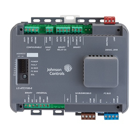
Page 16: Physical Features
Physical Features The following section describes the physical features of the ATC. Figure 6: Advanced Terminal Unit Controller Physical Features ATC1510 Advanced Terminal Unit Controller Installation Guide... - Page 17 10 A relay output 240 VAC power input FC Bus FC Bus EOL switch SA Bus SA Bus RJ12 Universal inputs Binary inputs Cover screw Address switch Status LEDs Figure 7: Controller and Mounting Dimensions, mm (in.) ATC1510 Advanced Terminal Unit Controller Installation Guide...
-
Page 18: Technical Specifications
Same circuit as modules logic circuitry +15 VDC, 200 mA SELV, Limited Power (<15 Watts), Class 2 Processor Renesas RX631 32-bit microcontroller, 2 MB Flash, 128 KB RAM ® External Memory 16 MB flash memory and 8 MB RAM ATC1510 Advanced Terminal Unit Controller Installation Guide... - Page 19 165 x 130 x 63 mm including terminals and mounting clips Dimensions (H x W x D) 165 x 165 x 63 mm (With IP20 Cover) Weight 0.6 kg (1 lbs 5 oz) ATC1510 Advanced Terminal Unit Controller Installation Guide...
-
Page 20: Points Of Single Contact
This product is covered by a limited warranty, details of which can be found at www.johnsoncontrols.com/ buildingswarranty. © 2019 Johnson Controls. All rights reserved. All specifications and other information shown were current as of document revision and are subject to change without notice.
Need help?
Do you have a question about the ATC1510 and is the answer not in the manual?
Questions and answers