
Related Manuals for Kewtech KT63 PLUS


Summary of Contents for Kewtech KT63 PLUS
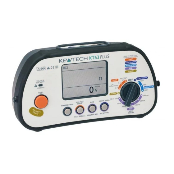
- Page 1 KT63 PLUS Multifunction Installation Tester Operating Instructions Kewtechcorp.com...
- Page 2 Index Safety information and explanation of symbols used ........4 Contents of the KT63 PLUS ............... 5 Inserting Batteries ..................7 Overview ....................8 Rotary Switch Functions ................9 Push Button Functions ................10 Continuity Test Function ................10 Insulation Test Function ................13 Special Polarity Test Pad .................
- Page 3 The KT63 PLUS Multifunction Tester has been designed and built to the highest standards providing you with a safe and simple solution to your test requirements. The KT63 PLUS tester is used to verify the safety of Commercial, Domestic and Industrial installations.
- Page 4 Read Before Using • To maintain operator safety use only specified accessories. • When working on live circuits, use of a proving unit such as the Kewtech KEWPROVE is recommended to establish correct function of the tester. • If the equipment is used in a manner not specified by the manufacturer, the protection afforded by the equipment may be impaired.
- Page 5 Safety Before using the KT63 PLUS read this instruction manual carefully to ensure a safe understanding of the symbols and use of the tester. See opposite page for a list of symbols used on the product and in this manual.
- Page 6 Contents of the KT63 PLUS Your Kewtech Multifunction Tester comes complete with: • Kewtech KT63 PLUS Multifunction Tester • Mains test lead with BS1363 Plug (KAMP12) • 3 Wire distribution board test lead set with probes and crocodile clips (ACC063) •...
- Page 7 Inserting batteries To insert batteries ensure the instrument is switched off and no test leads are connected. Remove battery cover from base of unit, insert batteries into holder ensuring correct polarity. Replace cover. Always use good quality LR6 AA (x6) Alkaline Batteries and do not mix old and new batteries. Re-chargeable batteries are not suitable.
- Page 8 Overview Front panel and controls Top view kewtechcorp.com...
- Page 9 Rotary switch functions All test functions are selected by using the main rotary switch. Power off. Continuity 250V Insulation test 500V Insulation test 1000V Insulation test 1000mA RCD test (Manual) 500mA RCD test (Manual) 300mA RCD test (Manual) 100mA RCD test (Manual) 10.
- Page 10 To ensure long battery life the KT63 PLUS will automatically power off when standing idle for 5 minutes. To power the KT63 PLUS back on either return the selector switch to “OFF” and then back to the test selection or simply press any of the four buttons under the display screen.
- Page 11 The brown test lead can be substituted by using the brown remote test probe supplied. This allows remote activation of the KT63 PLUS from the safety of the test probe ensuring that you are always looking at the point of contact and not the KT63 PLUS.
- Page 12 The KT63 PLUS is now correctly set up to perform continuity testing on a circuit. You can also set up your KT63 PLUS to be used in hands free mode on continuity by simply pressing the HANDS FREE button and then pressing test. HANDS FREE will flash at the top of the screen to indicate you are in hands free mode.
- Page 13 If the tester is connected to a live circuit (25V or greater), the LED will flash red and the hazard buzzer will sound. Your KT63 PLUS is fully protected and measured RMS voltage will be displayed on the secondary/lower display. Further testing after this point will be inhibited. To resume testing, disconnect the test leads and isolate the circuit.
- Page 14 The brown test lead can be substituted by using the red remote test probe supplied. This allows remote activation of the KT63 PLUS from the safety of the test probe ensuring that you are always looking at the point of contact and not the KT63 PLUS.
- Page 15 Hands Free Hands Free Insulation Testing. To enable the hands free feature simply press the ‘HANDS FREE’ button once. The ‘HANDS FREE’ annunciator will appear flashing on the display, press the test button to start testing. The ‘HANDS FREE’ annunciator will continue to flash until cancelled by a further press of the ‘HANDS FREE’...
- Page 16 3 colour coded prods/crocodile clips of the test lead should be connected to the corresponding Line, Neutral and Earth terminals. Your Kewtech KT63 PLUS tester has a special polarity test function. It is a little known fact that a system can be reverse...
- Page 17 Loop Impedance Testing Principle of Measurement – Hi-I Hi-I Line-Earth loop measurement takes place in several steps: The tester measures an unloaded half-cycle of the mains. The tester switches in load RL.This causes the mains circuit to be slightly attenuated due to the effective source impedance.
- Page 18 The KT63 PLUS Loop test function has 2 modes for Loop testing that allow the user to conduct the most accurate test possible depending whether or not the circuit under test is protected by an RCD.
- Page 19 Unlike most testers that only measure the resistance of the Loop, the high current mode of the KT63 PLUS will measure the impedance of the Loop which includes an element of reactance. This can be significant where the distribution board is close to the mains supply transformer and is therefore much more accurate than older Loop testing techniques.
- Page 20 Test Lead Configuration The KT63 PLUS Loop test function can be used with 2 types of connecting lead. It is important to understand and use the correct lead configuration for each test mode or you may not obtain the correct results.
- Page 21 The brown test lead can be substituted by using the remote test probe supplied. This allows remote activation of the KT63 PLUS from the safety of the test probe ensuring that you are always looking at the point of contact and not the KT63 PLUS.
- Page 22 Connect the test lead to the socket/circuit under test. Providing that the connections are correct and the supply voltage is within the correct range the VOLTAGE/POLARITY LED will light Green, the Kewtech KT63 PLUS will start taking some background measurements and will display the Line Neutral supply voltage Voltage will be displayed.
- Page 23 Warning Leakage currents in the circuit following the residual current protection device may influence the measurements. Potential fields of other earthing installations may influence the measurement. Special conditions in S-type residual current protective devices shall be taken into consideration. Equipment connected downstream of a residual current protective device (RCD) may cause considerable extension of the operating time.
- Page 24 Although fully protected against over voltage to 550VAC this tester should only be used on a 230V supply. The KT63 PLUS will test all the most commonly encountered RCD’s of both standard (AC & A) types and selective (ACS & AS) types across the full range of tests required by BS7671 (IET wiring regulations 2018).
- Page 25 The probes can be fitted with either prod tips or crocodile clips as required. Mains Supply Wiring and Voltage Test When first connected to a mains supply the KT63 PLUS will automatically conduct a safety test to ensure that the Live, Neutral/Earth conductors are correctly connected and that the supply voltage is in the acceptable range of 207-253V.
- Page 26 PASS Pass or Fail Result In addition to displaying the time taken for the RCD to trip the KT63 PLUS will also indicate whether it has passed or failed the test requirement of BS7671 (IET wiring regulations 2018). x 1/2...
- Page 27 Using three test leads, connect test leads to the L1 to Phase 1, L2 to Phase 2 and L3 to Phase 3. The KT63 PLUS will display .1 .2 .3 or .1 .3 .2 depending on the direction of phase rotation.
- Page 28 Warning Only use LR6 Alkaline replacement batteries. Please dispose of your batteries carefully. Batteries are made from important resources and chemicals, including lead, cadmium, zinc, lithium and mercury. If batteries are disposed of as normal waste, they’ll be taken to a landfill site and those resources will be lost and will contribute to the pollution of the environment.
- Page 29 Measurement Specifications and Accuracies High Current - High Resolution 2 wire test Live – Earth or Phase - Phase. Over Voltage System Voltage System Voltage Measurement Range Accuracy Protection Range Frequency (BS EN 61557-10) 0.000 Ω to 9.999 Ω ± (3% + 30mΩ) 100 - 440 V ac 50-60 Hz 550 V...
- Page 30 Continuity Measurement Short Circuit Max Lead Null Over Voltage Accuracy Open Circuit Range Current (at 2 Ω) Resistance Protection ± (3% + 2 > 4 V 0.00 Ω to 19.99 kΩ > 200 mA 4 Ω 550 V Fused digits) <...
- Page 31 Operating Uncertainties Insulation Loop Continuity Resistance Impedance Influence Quantity ΔT IΔN Influence EN 61557-4 EN 61557-6 EN61557-6 EN 61557-3 Quantity A – Intrinsic Uncertainty 0.8% 0.9% 5.6% 14.4% E1 – Position E2 – Supply Voltage 1.0% 0.8% 0.3% 1.3% E3 - Temperature 0.8% 4.9% 0.7%...
- Page 32 For repair and calibration please return to us at : Express Cal Unit 2, Shaw Wood Business Park, Shaw Wood Way, Doncaster DN2 5TB 01302 761044 expresscal@Kewtechcorp.com Kewtech Corporation Limited Midas House, Unit 2b, Stones Courtyard, High Street, Chesham, Bucks HP5 1DE 01494 792212 sales@Kewtechcorp.com Kewtechcorp.com...
Need help?
Do you have a question about the KT63 PLUS and is the answer not in the manual?
Questions and answers