
Summary of Contents for Reflex Fillcontrol Auto Series
- Page 1 06.07.2016 - Rev. B Fillcontrol Auto Make-up and degassing Fillcontrol Auto 2P Fillcontrol Auto 2PS Operating manual Original operating manual...
-
Page 3: Table Of Contents
Contents English Fillcontrol Au to M ake-up and d egassing 06.07.2016 - Rev. B Contents Notes on the operating manual..............................5 Liability and guarantee................................... 5 Safety........................................ 6 Explanation of symbols ..................................6 3.1.1 Symbols and notes used ..............................6 Personnel requirements ..................................7 Personal protective equipment ................................ - Page 4 Inspection of pressure-carrying components ..........................50 10.5 Maintenance certificate ..................................51 Disassembly ....................................52 Annex ......................................53 12.1 Reflex Customer Service ..................................53 12.2 Guarantee ......................................53 12.3 Conformity and standards ................................. 53 4 — English Fillcontrol Auto Make-up and degassing — 06.07.2016 - Rev. B...
-
Page 5: Notes On The Operating Manual
Reflex Winkelmann GmbH accepts no liability for any damage resulting from failure to observe the information in this operating manual. In addition to the requirements set out in this operating manual, national statutory regulations and provisions in the country of installation must also be complied with (concerning accident prevention, environment protection, safe and professional work practices, etc.). -
Page 6: Safety
Safety Safety Explanation of symbols 3.1.1 Symbols and notes used The following symbols and signal words are used in this operating manual. DANGER Danger of death and/or serious damage to health • The sign, in combination with the signal word 'Danger', indicates imminent danger; failure to observe the safety information will result in death or severe (irreversible) injuries. -
Page 7: Personnel Requirements
Safety Personnel requirements Only specialist personnel or specifically trained personnel may install and operate the equipment. The electric connections and the wiring of the device must be executed by a specialist in accordance with all applicable national and local regulations. Personal protective equipment When working at the system, wear the stipulated personal equipment such as hearing and eye protection, safety boots, helmet, protective clothing, protective gloves. -
Page 8: Inadmissible Operating Conditions
Safety Inadmissible operating conditions The device is not suitable for the following applications: • Pressure maintaining station for the facility system. • Mobile system operation. • Outdoor operation. • Usage with these media: – Mineral oils – Flammable fluids • Usage with these water types: –... -
Page 9: Description Of The Device
Description of the device Description of the device Description The devices combine the functions makeup and degassing of water for the plant system. The system separator tank ensures the separation of the plant system from the mains water supply. • Fillcontrol Auto 2P. -
Page 10: Overview
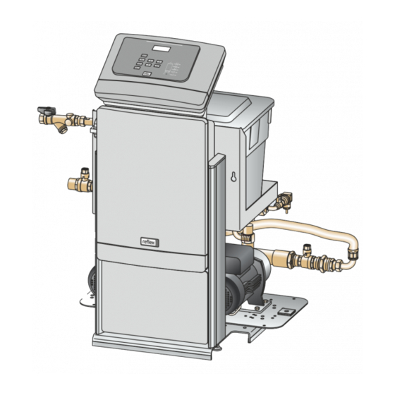
Description of the device Overview 4.2.1 Fillcontrol Auto 2P Operating unit Pump Control cabinet System separator vessel 4.2.2 Fillcontrol Auto 2PS Operating unit System separator vessel Control cabinet Vacuum spray pipe Pump 10 — English Fillcontrol Auto Make-up and degassing — 06.07.2016 - Rev. B... -
Page 11: Identification
Description of the device Identification 4.3.1 Nameplate The nameplate provides information about the manufacturer, the year of manufacture, the manufacturing number and the technical data. Information on nameplate Meaning Type Device name Serial No. Serial number Minimum/maximum min. / max. allowable pressure P permissible pressure max. -
Page 12: Function
Description of the device Function 4.4.1 Fillcontrol Auto 2P Operating unit Pump Main switch Pump Control cabinet System connection System separator vessel Fresh-water system connection Pressure transducer The pressure transducer sends a signal to the controller if the pressure drops below the filling pressure of the facility system. The controller activates the pumps. -
Page 13: Fillcontrol Auto 2Ps
Description of the device 4.4.2 Fillcontrol Auto 2PS Vacuum gauge Vacuum spray tube Motor ball valve Ball valve Connection of degassing line with dirt trap Pressure sensor Automatic quick venting unit Pump Operating unit Pump Main switch System connection Control cabinet Insufficient water switch Drainage cock Connection, fresh-water system with dirt trap... - Page 14 Description of the device The degassing operation in the vacuum spray pipe uses timer-controlled cycles. Vacuum is drawn Idling time Injection Pump Discharge A degassing cycle comprises the following phases: Vacuum is drawn. • The pump draws a vacuum in the spray tube until the water saturation pressure is reached. For cold water, the vacuum gauge indicates a vacuum of - 1 bar.
-
Page 15: Scope Of Delivery
Optional equipment and accessories The following optional equipment and accessories are available for this device: • "FQIRA+" contact water meter. • Softening with Reflex Fillsoft. • Expansions for Reflex Basic controllers: – I/O modules – Bus modules: • Lonworks Digital •... -
Page 16: Technical Data
Technical data Technical data Note! The following values apply for all systems: – Permissible ambient temperature: >0 °C – 45 °C – Degree of protection: IP 54 – Noise level: 55 dB Electrical system Power output Power supply Fusing Number of RS-485 Type I/O module (V / Hz) -
Page 17: Installation
Confirm that installation and start-up have been carried out correctly using the installation, start-up and maintenance certificate. This action is a prerequisite for the making of warranty claims. – Have the Reflex Customer Service carry out commissioning and the annual maintenance. Fillcontrol Auto Make-up and degassing — 06.07.2016 - Rev. B English — 17... -
Page 18: Installation Conditions
Installation Installation conditions 6.1.1 Incoming inspection Prior to shipping, this device was carefully inspected and packed. Damages during transport cannot be excluded. Proceed as follows: Upon receipt of the goods, check the shipment for • completeness and • possible transport damage. Document any damage. -
Page 19: Execution
Installation Execution ATTENTION Damage due to improper installation Additional device stresses may arise due to the connection of pipes or system equipment. • Ensure that pipes are connected from the device to the system without stresses being induced. • If necessary, provide support structures for the pipes or equipment. Note! Starting up of the pump causes vibration in the device. -
Page 20: Floor Mounting
Installation 6.3.2 Floor mounting The device is installed on the floor. Select the attachment means according to the floor properties. Comply with the following instructions: • The device is installed sufficiently close to the diaphragm expansion tank. – You ensure so that the pressure sensor is able to measure the filling pressure. -
Page 21: Hydraulic Connection
Installation 6.3.3 Hydraulic connection 6.3.3.1 Connection to the facility system Note! Starting up of the pump causes vibration in the device. This transfers loud noises into the system pipes. – Connect the pipes to the device using flexible connections. 6.3.4 Fillcontrol Auto 2P The device within a heating system with static pressure maintenance via a diaphragm expansion tank. -
Page 22: Fillcontrol Auto 2Ps
Installation 6.3.5 Fillcontrol Auto 2PS The device within a heating system with static pressure maintenance via a diaphragm expansion tank. Diaphragm expansion tank Vacuum spray pipe Make-up line Motor ball valve Degassing line System separator vessel Pump Main volume flow •... - Page 23 Installation Hydraulic connection, with Fillcontrol Auto 2PS as example. Make-up line Degassing line • Fillcontrol Auto 2PS • Fillcontrol Auto 2PS • Fillcontrol Auto 2P Device connection to the facility system: • Fillcontrol Auto 2PS. – Make-up line "1" for degassed water from the device to the facility system. –...
-
Page 24: Electrical Connection
Installation Electrical connection DANGER Risk of serious injury or death due to electric shock. If live parts are touched, there is risk of life-threatening injuries. • Ensure that the system is voltage-free before installing the device. • Ensure that the system is secured and cannot be reactivated by other persons. •... -
Page 25: Control Cabinet Terminal Plan
Installation 6.4.1 Control cabinet terminal plan Pressure Fuses Level Terminal Designation Signal Notes X0/ 1 User supplied X0/ 2 Supply (230 V) • Wiring at the terminal block next to the fuses X0/ 3 Is installed Makeup (230 V) • Fillcontrol Auto 2PS Floating signal contact 1 User supplied, optional... - Page 26 Installation Terminal Designation Signal Notes Pump 2 (230 V) Is installed Voltage supply Expansion circuit board • Fillcontrol 2P +24 V Relay (N.O.) 1 Optional relay output Relay (N.O.) 2 Optional relay output Relay (N.O.) 3 Optional relay output Relay (N.O.) 4 Optional relay output Relay (N.O.) 5 Optional relay output...
-
Page 27: Terminal Plan, Operating Unit
Installation 6.4.2 Terminal plan, operating unit Supply RS-485 interface I/O interface Terminal number Signal Function Wiring 10 V AC 10 V supply Factory T x D I/O interface Factory • Interface to the main circuit board R x D +5 V RS-485 interface User supplied Shielding... -
Page 28: Installation And Commissioning Certificate
Installation Installation and commissioning certificate Data shown on the nameplate: Type: Serial number: This device has been installed and commissioned in accordance to the instructions provided in the Operating Manual. The settings in the controller match the local conditions. Note! When any factory-set values of the device are changed, you must enter this information in the Maintenance certificate, see chapter 10.5 "Maintenance certificate "... -
Page 29: Commissioning
This action is a prerequisite for the making of warranty claims. – Have the Reflex Customer Service carry out commissioning and the annual maintenance. Requirements for initial commissioning The device will be ready for commissioning when the tasks described in the "Installation" chapter have been completed. -
Page 30: Filling The Device With Water
Commissioning Filling the device with water CAUTION Risk of injury due to pump start-up Hand injuries may occur when the pump starts up if you turn the pump motor at the impeller using a screwdriver. • Switch the pump to a zero-volts state before turning the pump at the fan wheel with a screwdriver. ATTENTION Device damage due to pump start-up Pump damage may occur when the pump starts up if you turn the pump motor at the impeller using a screwdriver. -
Page 31: Modifying The Controller's Start Routine
Commissioning Modifying the controller's start routine The start routine is used to set the required parameters for the device commissioning. It commences with the first activation of the controller and can be run only once. Parameters can be changed or checked in the customer menu after the start routine has terminated, see chapter 9.2.1 "Customer menu"... -
Page 32: Function Test
Commissioning Function test 7.6.1 Vacuum test Perform a vacuum test only for Fillcontrol Auto 2PS. Proceed as follows: Close the ball valve (2) with the dirt trap (1) of the degassing line. The second ball valve (3) remains open. Generate a vacuum with the manual mode of the controller. •... -
Page 33: Pump Test
Commissioning 7.6.2 Pump test At the device, execute a function test for the pumps. Set the device controller to manual mode. In manual mode, you manually activate and deactivate the pumps. • Press "Manual" on the controller's operator panel. – The "Manual"... -
Page 34: Use The Device To Fill The Facility System With Water
Commissioning Use the device to fill the facility system with water Use the unit for filling the facility system with water. Proceed as follows: 1. Open the shut-off valves. • In the expansion and degassing lines. • Shut-off devices up- and downstream of the system separator tank. Switch the controller to Manual mode. -
Page 35: Starting Automatic Mode
Commissioning Starting Automatic mode Automatic operation can be started after initial commissioning. The following prerequisites must be met for automatic operation: • "P " minimum working pressure is entered in the controller. • The device is filled with water. • All required parameters are defined in the controller. -
Page 36: Operation
Operation Operation Operating modes 8.1.1 Automatic mode Automatic mode is the operating mode for continuous device operation. In Automatic mode, the controller monitors and activates or deactivates the device functions. Faults are displayed and evaluated. The following functions are active in Automatic mode: •... -
Page 37: Stop Mode
Operation 8.1.2.2 Fillcontrol Auto 2PS Manual mode is used to test the functions during commissioning and to service the device. Manual mode enables you to select the following For performing a test run and service tasks: • "PU1" or "PU2" pumps. –... -
Page 38: Summer Operation
Operation 8.1.4 Summer operation The make-up with fresh water must be ensured even outside of the operation of the heating and cooling systems. Do not shut down the device when the pressure maintaining systems of the heating and cooling systems are in operation. 8.1.5 Restarting CAUTION... -
Page 39: Controller
Controller Controller Operator panel Manual • For tests and maintenance tasks • Confirm actions • The Manual LED illuminates green in manual mode Stop Error LED • For commissioning and entry of new values in the • The Error LED illuminates in the event of a fault controller •... -
Page 40: Configuring Settings In The Controller
Controller Configuring settings in the controller Use the Customer menu to display or correct system-specific values. In the course of commissioning, the factory settings must be adjusted for the system-specific conditions. For a description of the operation, see chapter 9.1 "Operator panel" on page 39 . Proceed as follows: All grey marked menu items must be reviewed during commissioning. - Page 41 Controller Note! The following settings apply to Fillcontrol Auto 2P and Fillcontrol Auto 2PS. Switch to the "Make-up" sub-menu. Make-up Switch to the next list item. Make-up Maximum time for a make-up cycle. Upon expiry of the set time, the system interrupts the Max.
- Page 42 Controller Switch to the fault memory or into the next main menu option. Fault memory The last 20 alarms are stored with fault type, date, time, and fault code. ER 01…xx See the chapter "Messages" for more information about the ER... messages. Switch to the parameter memory or into the next main menu option.
-
Page 43: Customer Menu
Controller 9.2.1 Customer menu Use the Customer menu to correct or determine system-specific values. In the course of commissioning, the factory settings must be adjusted for the system-specific conditions. A three-digit PM code is assigned to the setting options PM code Parameter Setting Remarks... -
Page 44: Service Menu
Controller 9.2.2 Service menu The Service menu is password-protected. Only Reflex service technicians are able to access this menu, see chapter 12.1 "Reflex Customer Service" on page 53 . Parameter Setting Remarks Pressurisation Pump "ON" + 0.3 bar Differential pressured added to the "P "... -
Page 45: Messages
Alarm causes can be eliminated by the operator or a specialist workshop. • If required, please contact the Reflex Customer Service. Note! Clearing of the cause must be confirmed by pressing the “Ack” button on the operator panel. All other alarms are automatically reset as soon as the cause has been eliminated. - Page 46 Controller ER Code Alarm Floating Cause Remedy Alarm reset contact Makeup cycles Set value exceeded • Check set value in the Quit Customer or Service menu • Seal the leak in the system Pressure Controller receives incorrect • Connect the plug Quit measurement signal...
- Page 47 ER Code Alarm Floating Cause Remedy Alarm reset contact EEPROM defective • EEPROM defective Contact the Reflex Customer Quit Service • Internal calculation error Undervoltage Supply voltage not achieved Check power supply Adjustment EPROM parameter memory Contact the Reflex Customer...
-
Page 48: Maintenance
• Reset the maintenance counter in the Customer menu. Note! Maintenance tasks must be carried out only by specialist personnel or the Reflex Customer Service. • Confirm the maintenance tasks, see chapter 10.5 "Maintenance certificate " on page 51 . -
Page 49: Maintenance Schedule
Maintenance 10.1 Maintenance schedule The maintenance schedule is a summary of maintenance tasks to be carried out regularly. Maintenance task Conditions Interval ▲ ■ ● = Check, = Service, = Clean ▲ ■ Check for leaks. Annually • Pumps • Screw connections •... -
Page 50: System Degassing Inspection
Maintenance 10.3 System degassing inspection Inspect the "SE" system degassing unit (only with Fillcontrol Auto 2PS). Proceed as follows: Press "Manual" at the controller to switch to manual mode. • The Auto LED at the operator panel flashes to visually indicate that manual mode is active. •... -
Page 51: Maintenance Certificate
Maintenance 10.5 Maintenance certificate All maintenance tasks have been completed according to the Reflex Installation, Operating and Maintenance Manual. Date Service organisation Signature Remarks Fillcontrol Auto Make-up and degassing — 06.07.2016 - Rev. B English — 51... -
Page 52: Disassembly
Disassembly Disassembly DANGER Risk of serious injury or death due to electric shock. If live parts are touched, there is risk of life-threatening injuries. • Ensure that the system is voltage-free before installing the device. • Ensure that the system is secured and cannot be reactivated by other persons. •... -
Page 53: Annex
Annex Annex 12.1 Reflex Customer Service Central customer service Central telephone number: +49 (0)2382 7069 - 0 Customer Service extension: +49 (0)2382 7069 - 9505 Fax: +49 (0)2382 7069 - 9588 E-mail: service@reflex.de Technical Hotline For questions about our products... - Page 56 Reflex Winkelmann GmbH Gersteinstraße 19 59227 Ahlen, Germany Telephone: +49 (0)2382 7069-0 Fax: +49 (0)2382 7069-9588 www.reflex.de...
Need help?
Do you have a question about the Fillcontrol Auto Series and is the answer not in the manual?
Questions and answers