Table of Contents
Advertisement
Quick Links
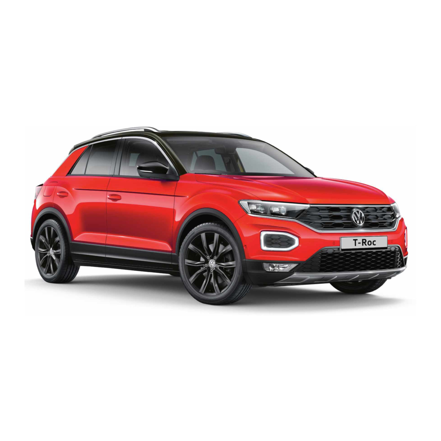
Front view
Fig. 2 Front view of the vehicle.
Key to ⇒ Fig. 2 :
Windscreen:
Vehicle identification number ⇒ Technical data
Windscreen wipers ⇒ Wipers ⇒ Wiper blades
Rain/Light Sensor in the area of the interior mirror ⇒ Rain/light sensor ⇒ Caring for and cleaning the
vehicle exterior
Sensor for lighting functions ⇒ Light functions ⇒ Caring for and cleaning the vehicle exterior
Bonnet opening lever ⇒ In the engine compartment
Behind the Volkswagen badge: radar sensor for assist systems ⇒ Caring for and cleaning the
vehicle exterior
Sensors for assist systems ⇒ Caring for and cleaning the vehicle exterior ⇒ Driver assist systems
Behind a cover: mounting for towing eye ⇒ Tow-starting or towing
Lights in the bumper ⇒ Lights ⇒ Changing bulbs
Advertisement
Table of Contents
Troubleshooting

Related Manuals for Volkswagen T-Roc


Summary of Contents for Volkswagen T-Roc
- Page 1 Sensor for lighting functions ⇒ Light functions ⇒ Caring for and cleaning the vehicle exterior Bonnet opening lever ⇒ In the engine compartment Behind the Volkswagen badge: radar sensor for assist systems ⇒ Caring for and cleaning the vehicle exterior Sensors for assist systems ⇒ Caring for and cleaning the vehicle exterior ⇒ Driver assist systems ...
- Page 2 Side view Fig. 3 Overview of the right side of the vehicle. Key to ⇒ Fig. 3 : Tail light cluster ⇒ Lights ⇒ Changing bulbs Tank flap ⇒ Fuel and emission control Door release lever ⇒ Doors and central locking button Roof railing ⇒...
- Page 3 Rear window: Rear window heating ⇒ Heating and air conditioning system Rear window wiper ⇒ Wipers ⇒ Wiper blades Volkswagen badge: To open the boot lid ⇒ Opening and closing the boot lid With camera for assist systems ⇒ Driver assist systems ...
- Page 4 Driver door Fig. 5 Controls in the driver door (left-hand drive vehicle). The location is mirrored in right-hand drive vehicles. Key to ⇒ Fig. 5 : Area: Switch for exterior mirror adjustment and heating ⇒ Exterior mirrors Buttons for operating the electric windows ⇒ Windows Door release lever ⇒...
- Page 5 Driver side Fig. 6 Overview of the driver side (left-hand drive vehicles). Fig. 7 Overview of the driver side (right-hand drive vehicles). Key to ⇒ Fig. 6 and ⇒ Fig. 7 :...
- Page 6 Bonnet release lever ⇒ In the engine compartment Fuse box cover ⇒ Changing fuses Lever for adjusting the steering column position ⇒ Steering wheel Light switch ⇒ Vehicle lighting Turn signal and main beam lever ⇒ Vehicle lighting With switches and buttons for the driver assist systems ⇒ Button for driver assist systems ⇒ Driver assist systems ...
- Page 7 Centre console Fig. 8 Overview of the upper section of the centre console. Fig. 9 Overview of the lower section of the centre console. Key to ⇒ Fig. 8 : Infotainment system ⇒BookletInfotainment system, ⇒ Infotainment system controls and displays Vents ⇒ Heating and air conditioning system Buttons:...
- Page 8 ⇒ In an emergency Hazard warning lights ⇒ Airbag system Indicator lamp for the front passenger front airbag switch-off function Driver assist systems ⇒ Driver assist systems Controls for the air conditioning system, heating and fresh air system ⇒ Heating, ventilating, cooling ...
- Page 9 Front passenger side Fig. 10 Overview of the front passenger side (left-hand drive vehicles). The location is mirrored in right-hand drive vehicles. Key to ⇒ Fig. 10 : Vents ⇒ Heating and air conditioning system At the side of the dash panel: key-operated switch for disabling the front passenger front airbag ⇒...
- Page 10 Not all warning and indicator lamps are available in all markets. Indicator lamps which light up in the light switch are described in the chapter Lights ⇒ Lights . Symbol Meaning Central warning lamp. Observe the additional information on the instrument cluster display.
- Page 11 Symbol Meaning Engine speed limited ⇒ Troubleshooting . Electromechanical steering function reduced ⇒ Troubleshooting . Tyre monitoring system ⇒ Troubleshooting for Tyre Pressure Loss Indicator . Fault in the rain/light sensor ⇒ Fault in rain/light sensor , ⇒ Fault in rain/light sensor . Fault in wipers ⇒ Troubleshooting . Washer fluid level too low ⇒...
- Page 12 Symbol Meaning Auto Hold function ⇒ Auto Hold function . Adaptive Cruise Control (ACC) ⇒ Switching ACC on and off Speed limiter ⇒ Speed limiter . Lane keeping system (Lane Assist) ⇒ Driving with the lane keeping system . Main beam or headlight flasher ⇒ Switching main beam on and off . Coolant ⇒...
- Page 13 Symbol Meaning Trailer turn signal ⇒ Does not apply in China and Japan: trailer turn signals indicator lamp . Additional displays: offroad mode Symbol Meaning Hill Descent Control ⇒ Downhill speed control . Offroad driving profile active ⇒ Driving profile selection and 4MOTION Active Control . Additional displays: diesel vehicles Symbol Meaning AdBlue®...
- Page 14 Instrument cluster Introduction This chapter contains information on the followingsubjects: ⇒ Analogue instrument cluster ⇒ Rev counter ⇒ Digital instrument cluster (Active Info Display) ⇒ Displays ⇒ Instrument cluster menus ⇒ Service menu ⇒ Driving data display (multifunction display) ⇒ Warning and information messages ⇒...
- Page 15 Analogue instrument cluster Fig. 11 Analogue instrument cluster in the dash panel. First read and observe the introductoryinformation and safety warnings⇒ Introduction Descriptions of the instruments ⇒ Fig. 11 : Rev counter (running engine speed in revolutions x 1,000 per minute) ⇒ Rev counter . Coolant temperature display⇒...
- Page 16 NOTICE When the engine is cold, avoid high engine speeds, driving at full throttle and overloading the engine. The needle on the rev counter should only briefly point into the red area, as engine damage may otherwise be incurred. Changing up a gear early will help to save fuel and reduce engine noise. Digital instrument cluster (Active Info Display) First read and observe the introductory information and safety warnings⇒...
- Page 17 Information profiles Various, topic-specific information profiles can be selected via the Active Info Display menu option in the vehicle settings of the Infotainment system ⇒ Vehicle settings menu . Depending on the selected information profile, the Active Info Display shows additional information in the centre of the round instruments, or the round instruments are hidden and the additional information is displayed across the whole width of the display.
- Page 18 OR: press the arrow button on the multifunction steering wheel to select the required map size. A frame appears around the selected option. Press the button on the multifunction steering wheel to confirm your selection. With some equipment levels, navigation is shown on two screens or only one. The navigation map can be displayed on the Active Info Display and Infotainment system or only on the Infotainment system display.
- Page 19 Personalisation: welcome and user selection ⇒ Personalisation . Open doors, bonnet and boot lid The instrument cluster display indicates if any doors, the engine compartment or boot lid are open once the vehicle has been unlocked, and while the vehicle is in motion. In some cases, a signal tone is also given.
- Page 20 When the ignition is switched on, depending on the equipment level, the instrument cluster display shows the current direction of travel in the form of an abbreviation, e.g. NW for north west. The graphic compass display is also available when the Infotainment system is switched on and route guidance is not active.
- Page 21 A qualified workshop can program and modify other functions depending on the vehicle equipment level. Volkswagen recommends using a Volkswagen dealership for this purpose. Some menu options can be accessed only when the vehicle is stationary. Driving data⇒ Driving data display (multifunction display) ...
- Page 22 First read and observe the introductoryinformation and safety warnings⇒ Introduction Settings can be made in the Service menu1) depending on the vehicle equipment. Opening the Service menu To open the Service menu, select the Range information profile and press and hold the OK button on the multifunction steering wheel for around four seconds.
- Page 23 The memory will be deleted if the journey is interrupted for more than two hours. Since refuelling memory Display and storage of the collected driving and consumption values. The memory is deleted when the tank is refilled. Long-term memory The memory collects driving data for up to 19 hours and 59 minutes or 99 hours and 59 minutes of driving time or 1,999.9 km or 9,999.9 km distance covered.
- Page 24 Within around five seconds, set the speed with the rocker switch on the wiper lever or the buttons on the multifunction steering wheel. Then press the button or wait a few seconds. The speed is now saved and the warning is activated. To deactivate, press the button again.
- Page 25 Driver Alert System (recommendation for rest breaks) First read and observe the introductoryinformation and safety warnings⇒ Introduction The Driver Alert System informs the driver if their driving shows signs of tiredness. Fig. 13 On the instrument cluster display: Driver Alert System symbol. Function and operation The Driver Alert System determines the driving behaviour of the driver at the start of a journey and uses this to calculate a fatigue assessment.
- Page 26 Sporty driving style. Towing a heavy/long trailer. The driver is distracted. The Driver Alert System is reset in the following situations: The ignition is switched off. The driver seat belt is unfastened and the driver door is opened. The vehicle has been stationary for longer than 15 minutes. The Driver Alert System is automatically reset in the event of an extended period of driving at slow speeds (speed less than 60 km/h (37 mph)).
- Page 27 Dynamic Road Sign Display (Sign Assist) Fig. 14 On the instrument cluster display: examples of recognised speed limits and overtaking restrictions with accompanying additional signs. First read and observe the introductoryinformation and safety warnings⇒ Introduction Dynamic Road Sign Display uses a camera in the base of the interior mirror to monitor standard road signs and informs the driver of any detected speed limits or overtaking restrictions.
- Page 28 Display of road signs After validation and evaluation of the information from the camera, the Infotainment system and the current vehicle data, the activated Dynamic Road Sign Display shows up to three valid road signs ⇒ Fig. 14 with the accompanying additional signs: 1st position:The road sign that currently applies for the driver is shown on the left-hand side of the display, e.g.
- Page 29 Partially or fully hidden traffic signs, e.g. by trees, snow, dirt or other vehicles. Road signs that do not correspond to the standard design. Damaged or bent traffic signs. Variable road signs on gantries (changeable road sign display using LEDs or other light sources). Out-of-date map material in the Infotainment system.
- Page 30 Time First read and observe the introductory information and safety warnings⇒ Introduction Press the button or function button. Press the Vehicle and function buttons. Select the Time and date menu option to set the time ⇒ Vehicle settings menu . To set the time (on all vehicle clocks), press and hold the button in the instrument cluster until the word Time appears in the display ⇒...
- Page 31 The following higher-level menus can be displayed: Lap timer Lap (with the current lap number) Statistics Switching between the menus Vehicles without multifunction steering wheel: on the wiper lever ⇒ Operating the instrument cluster . Press the rocker switch Vehicles with multifunction steering wheel: button ⇒...
- Page 32 When the vehicle is in motion, use the lap timer only in driving situations which are easy to control. Fuel gauge Fig. 15 Fuel gauge in the analogue instrument cluster. Fig. 16 Fuel gauge in the Active Info Display. First read and observe the introductoryinformation and safety warnings⇒ Introduction ...
- Page 33 WARNING Driving when the fuel level is too low can lead to the vehicle coming to a standstill in traffic, potentially causing accidents and serious injuries. When the fuel level is too low, the fuel supply to the engine could be irregular, especially when driving up or down hills and inclines.
- Page 34 Fig. 18 Coolant temperature gauge in the Active Info Display. First read and observe the introductory information and safety warnings⇒ Introduction Cold area. The engine has not yet reached operating temperature. Avoid high engine revs and heavy engine loads until the engine is warm. Normal area.
- Page 35 In vehicles with flexible oil change service, the service intervals are calculated on an individual basis. Technical progress has made it possible to considerably reduce servicing requirements. An oil change service must only be carried out when required by the vehicle. The individual conditions in which the vehicle is used and the driver's personal driving style are taken into account.
- Page 36 If the service or the inspection was not performed by a Volkswagen dealership, the display can be reset as follows: Vehicles with analogue instrument cluster. Switch off the ignition. button in the instrument cluster ⇒ Instrument cluster . Press and hold the Switch on the ignition again.
- Page 37 The buttons on the wiper lever are omitted in vehicles equipped with a multifunction steering wheel ⇒ Operating using the wiper lever . WARNING Accidents and injuries can occur if the driver is distracted. Never operate the menus on the instrument cluster display while the vehicle is in motion. Check the system settings after charging or replacing the 12-volt vehicle battery.
- Page 38 In the menu displayed, press the rocker switch ⇒ Fig. 20 ② on the wiper lever upwards or downwards until the desired menu option is marked. A frame appears around the selected option. Press the ⇒ Fig. 20 ① button to make the required changes. A tick indicates that the particular system or function is active.
- Page 39 ⇒ Fig. 21 until the desired menu option is In the displayed menu, press the arrow keys marked. A frame appears around the selected option. button ⇒ Fig. 21 to make the required changes. A tick indicates that the particular Press the system or function is active.
- Page 40 Introduction This chapter contains information on the followingsubjects: ⇒ Vehicle settings menu ⇒ Performance monitor ⇒ Lap timer ⇒ Personalisation The Infotainment system combines key vehicle systems in a central operating unit, e.g. menu settings, radio or navigation system. General information on operation The following section contains relevant information on the settings that can be adjusted in the Vehicle settings menu.
- Page 41 Always drive carefully and responsibly. When you start the engine after the 12-volt vehicle battery has been totally discharged or changed, you may find that system settings (time, date, personal convenience settings and programming) and user accounts have been changed or deleted. Check and correct the settings as necessary once the 12-volt vehicle battery has been sufficiently charged.
- Page 42 Key to ⇒ Fig. 23 : Display areas. Arrow buttons for changing to the lap timer. Opening the performance monitor Press the MENU button or function button on the Infotainment system. Touch the Vehicle function button. Touch the Selection function button. Touch the Sport function button.
- Page 43 its operating temperature. The needle may move further in a clockwise direction under high engine loads and at high outside temperatures. This is no cause for concern unless the indicator lamp in the instrument cluster display is lit up or flashing ⇒ Engine oil . Adapting the display areas to the driving situation Choose the three possible instruments corresponding to your individual driving style and the driving situation.
- Page 44 Fig. 25 Function button on the Infotainment system display: time measurement for paused, current and completed lap. Key to ⇒ Fig. 24 and ⇒ Fig. 25 Stopwatch. Function button with current lap time. Stored lap times. Start or continue time measurement (possible only when the ignition is switched on). Press Start to start time measurement.
- Page 45 Opening the lap timer Press the MENU button or function button, depending on the version of the Infotainment system. Touch the Vehicle function button. Touch the Selection function button. Touch the Sport function button. The performance monitor is displayed. Touch one of the arrow buttons ⇒ Fig. 23 ② in the performance monitor to change to the lap timer.
- Page 46 When you select a user account, the saved vehicle settings are activated. User management and settings When the ignition is switched on, you can use the Personalisation menu in the Infotainment system for user management and to make settings. The menu can be accessed via the vehicle settings in the Infotainment system.
- Page 47 General notes Checklist Observe the following information both before and during every journey to ensure your own safety, and the safety of all passengers and other road users ⇒ : Check that all lights and turn signals are working properly. Check the tyre pressure and fuel level Tyre pressure, Fuel gauge.
- Page 48 In some countries, special safety standards and emissions-related legislation apply that may differ from the build status of the vehicle. Volkswagen recommends that you visit your Volkswagen dealership before travelling abroad to find out about any legal requirements and the following issues at your destination: Does the vehicle need any technical modifications for driving abroad, e.g.
- Page 49 Are there any Volkswagen dealerships in the destination country? Is fuel in the adequate quality available Fuel and emission control? Are the correct service fluids that comply with Volkswagen specifications available in the destination country Service fluids and consumables? Will the navigation function in the factory-fitted Infotainment system work with the available...
- Page 50 NOTICE Volkswagen is not responsible for any vehicle damage caused by low-quality fuel, inadequate servicing work or non-availability of Genuine Parts. Observe the instructions and information for vehicles with an N1 approval ⇒ Information about...
- Page 51 You should therefore have your vehicle serviced according to the Volkswagen guidelines. Some work may have to be carried out before the date of the next service if the vehicle is subjected to severe operating conditions. Severe operating conditions are, for example, regular stop-and-go driving or driving in areas with high levels of dust.
- Page 52 deploying airbag strikes a vehicle occupant who has assumed an incorrect sitting position. The driver is responsible for all occupants transported in the vehicle, especially children. The following list contains examples of sitting positions that can be dangerous for all vehicle occupants.
- Page 53 Volkswagen recommends using a Volkswagen dealership for this purpose. Volkswagen recommends the following sitting positions for your own safety and to reduce the level of injury in the event of a sudden braking manoeuvre or an accident:...
- Page 54 ⇒ . The qualified workshop must use the correct spare parts which are compatible with the vehicle, equipment level and model year. Volkswagen recommends using a Volkswagen dealership for this purpose. WARNING Incorrectly fastened or unfastened seat belts increase the risk of severe or fatal injuries.
- Page 55 Have damaged seat belts immediately replaced by new seat belts that have been approved by Volkswagen for the vehicle. Seat belts subjected to stress and stretched during an accident must be replaced by a qualified workshop. Renewal may be necessary even if there is no apparent damage.
- Page 56 Fig. 27 On the instrument cluster display: warning lamp. Fig. 28 On the instrument cluster display: seat belt status for the rear seats. First read and observe the introductoryinformation and safety warnings⇒ Introduction A signal tone will sound for a few seconds if the seat belts are not fastened as the vehicle pulls off and reaches a speed of more than approximately 25 km/h (15 mph), or if the seat belts are unfastened while the vehicle is in motion.
- Page 57 Fig. 29 Unbelted occupants in a vehicle heading towards a brick wall. Fig. 30 Unbelted occupants in a vehicle striking a brick wall. First read and observe the introductoryinformation and safety warnings⇒ Introduction The physical principles involved in a frontal collision are relatively simple. As soon as the vehicle is in motion ⇒...
- Page 58 Fig. 31 An unbelted driver is thrown forward. Fig. 32 The unbelted rear passenger is thrown forward and strikes the belted driver. First read and observe the introductoryinformation and safety warnings⇒ Introduction Many people believe that the occupants can brace their weight with their hands in a minor collision. This is not true.
- Page 59 Seat belt protection Fig. 33 Driver restrained by a properly worn seat belt during a sudden braking manoeuvre. First read and observe the introductoryinformation and safety warnings⇒ Introduction Properly worn seat belts can make a major difference. When worn correctly, seat belts hold the vehicle occupants in the correct sitting positions and considerably reduce the kinetic energy in the event of an accident.
- Page 60 Using seat belts ⇒ : Regularly check the condition of all seat belts. Keep the seat belts clean. Avoid allowing any foreign bodies or fluids to get on to the seat belt or latch plate or into the slot for the seat belt buckle.
- Page 61 Fig. 34 Inserting the seat belt latch plate into the buckle. Fig. 35 Removing the latch plate from the buckle. First read and observe the introductoryinformation and safety warnings⇒ Introduction If worn properly, seat belts hold the vehicle occupants in the correct sitting position during an accident or braking manoeuvre, providing maximum protection ⇒...
- Page 62 Guide the belt back by hand so that it rolls up easily, without twisting the seat belt and without damaging the trim. WARNING Incorrect seat belt routing can cause severe or fatal injuries in the event of an accident. The seat belts offer best protection only when the backrests are in an upright position and the seat belts have been fastened properly according to the occupant's size.
- Page 63 The shoulder part of the seat belt must always lie on the centre of the shoulder, never across the neck, over or under the arm or behind the back. The lap part of the seat belt must always lie across the pelvis, never across the stomach. The seat belt must always lie flat and snugly on the body.
- Page 64 Volkswagen recommends using a Volkswagen dealership for this purpose. Seat belt height adjuster Fig. 38 Next to the front seats: seat belt height adjuster. First read and observe the introductoryinformation and safety warnings⇒ Introduction The seat belt height adjusters for the front seats can be used to adjust the position of the seat belt on the shoulder so that it can be fastened properly: Push the shoulder belt guide together in the direction of the arrows and hold ⇒...
- Page 65 The belt tensioners are activated by sensors in the event of severe frontal, side and rear collisions. They tighten the seat belts against the direction in which they are pulled. Any slack in the seat belt is retracted, which can reduce the forward movement of the vehicle occupants and their movement in the direction of the impact.
- Page 66 First read and observe the introductoryinformation and safety warnings⇒ Introduction The proactive occupant protection system is an assistance system that initiates measures to protect vehicle occupants in dangerous situations. However, the system cannot prevent a collision. The full range of functions of the proactive occupant protection system will be available only if the function has been activated in the Infotainment system, no special driving profile has been selected and there are no malfunctions ⇒...
- Page 67 Reflective objects such as safety barriers, tunnel entrances, heavy rain and ice can impair the performance of the proactive occupant protection system and thus prevent it from detecting a collision risk. Incorrect system activation can occur. WARNING Accidents and injuries can occur if the driver is distracted. Never change settings in the Infotainment system when the vehicle is in motion.
- Page 68 Airbags that have been triggered, and any affected system parts, must immediately be replaced with new parts that are approved by Volkswagen for the vehicle. Repairs and modifications to your vehicle should be carried out only by a qualified workshop.
- Page 69 Types of front passenger front airbag system First read and observe the introductoryinformation and safety warnings⇒ Introduction Volkswagen offers two different front passenger front airbag systems: Features of the front passenger Features of the front passenger front airbag that can be...
- Page 70 Volkswagen offers two different front passenger front airbag systems: Features of the front passenger Features of the front passenger front airbag that can be front airbag that can be switched switched off manually using the key-operated switch ⇒ Switching the front passenger front airbag on and off .
- Page 71 The airbags can protect vehicle occupants during frontal and side collisions by reducing their movement in the direction of the collision. Each triggered airbag is filled by a gas generator. This causes the airbag covers to break open and the airbags inflate forcefully to cover their deployment zones within milliseconds.
- Page 72 Front airbags Fig. 40 Location and deployment zone of the driver front airbag. Fig. 41 Location and deployment zone of the front passenger front airbag. First read and observe the introductoryinformation and safety warnings⇒ Introduction In conjunction with the seat belts, the front airbag system gives the front occupants additional protection for the head and chest in the event of a severe frontal collision.
- Page 73 Never attach any objects, such as drink or telephone holders, to the covers of the airbags or anywhere in the airbag deployment zone. No other people, animals or objects may be carried between the occupants of the front seats and the airbag deployment zone.
- Page 74 Switch off the ignition. Open the door on the front passenger side. Fold the key bit of the vehicle key all the way out ⇒ Vehicle key . Insert the key bit into the key-operated switch on the dash panel ⇒ Fig. 42 until you feel the second point of resistance.
- Page 75 WARNING The front passenger front airbag should be switched off only in exceptional circumstances. To prevent damage to the airbag system, switch the front passenger front airbag on and off only when the ignition is switched off. It is the driver's responsibility to ensure that the key-operated switch is set to the correct position. Switch off the front passenger front airbag only if in exceptional circumstances a child seat is fitted on the front passenger seat.
- Page 76 For safety reasons, child seats must always be fitted to the rear seats ⇒ Fitting and using child seats . Volkswagen recommends child seats from the Volkswagen range of accessories. These child seats have been developed and approved for use in Volkswagen vehicles.
- Page 77 Fig. 43 Example illustrations of child seats. First read and observe the introductoryinformation and safety warnings⇒ Introduction Use only child seats that have been officially approved and are suitable for the child. Standards for child seats The regulations ECE-R 44 or ECE-R 1291) apply to child seats in the European Union. Both regulations apply in parallel.
- Page 78 Child seats with a backrest have integrated seat belt routing and side cushions, and so provide better protection than booster seats with no backrest. Volkswagen therefore recommends the use of child seats with a backrest. Group 2 child seats are for children up to the age of about seven, group 3 child seats for those older than seven.
- Page 79 Fig. 45 Illustration: airbag label on the B-pillar. First read and observe the introductoryinformation and safety warnings⇒ Introduction Country-specific requirements The standards and regulations governing the use of child seats and child seat securing mechanisms differ from country to country. Not all countries allow you to transport children on the front passenger seat.
- Page 80 Some child seats are not suitable for use on the front passenger seat. The child seat must be specially approved by the manufacturer for use on the front passenger seat in vehicles with front and side airbags. Volkswagen dealerships keep an up-to-date list of approved child seats. DANGER If you use a rear-facing child seat on the front passenger seat, the child in it is at increased risk of sustaining critical or fatal injuries in the event of an accident.
- Page 81 ⇒ Securing child seats with a seat belt . Additional securing points: Recommended child seat securing systems Volkswagen recommends that child seats are secured as follows: Infant carrier or rear-facing child seat: ISOFIX and support foot. Front-facing child seat: ISOFIX and top tether and possibly also support foot.
- Page 82 Incorrect use of the support foot can cause severe or fatal injuries. Ensure that the support foot is always correctly and safely installed. Securing a child seat with ISOFIX Fig. 46 Markings identifying the ISOFIX anchor points for child seats. Fig.
- Page 83 Group Size class Front passenger seat Outer rear seats Centre rear seat Group 2: 15 to 25 kg – IL-SU Group 3: 22 to 36 kg – IL-SU i-Size child restraint system – Size class: the size class shown corresponds to the permissible weight range of the child using the seat.
- Page 84 Insert the latch plate into the buckle for the appropriate seat and push it down until it audible locks into place. In an emergency Making you and your vehicle safe Observe any legislation concerning the safety of a broken-down vehicle. For example, many countries stipulate that you have to switch on the hazard warning lights and wear a high-visibility waistcoat ⇒...
- Page 85 When the hazard warning lights are switched on, for example if you are being towed, you can still indicate a change in direction or lane change by operating the turn signal. The hazard warning lights will be interrupted temporarily. Switch on the hazard warning lights, e.g. in the following situations: When traffic ahead suddenly starts moving more slowly or you reach the tail end of a traffic jam to warn vehicles behind you.
- Page 86 NOTICE When pushing the vehicle by hand, do not press on the tail light clusters, the rear spoiler or large panels. This could damage the vehicle and the rear spoiler could become detached. The 12-volt vehicle battery will discharge if the hazard warning lights are left on over a long period of time –...
- Page 87 Depending on the vehicle equipment, the high-visibility waistcoat may be located in a stowage compartment in the front door trim or in the stowage compartment on the front passenger side ⇒ Driver door , ⇒ Front passenger side . The high-visibility waistcoat must comply with legal requirements. Fire extinguisher Depending on the equipment, a fire extinguisher may be located in a holder in the footwell under the front passenger seat.
- Page 88 Lit up red: system error. Voice service availability is restricted. Volkswagen recommends consulting a specialist workshop. Lit up green: voice services are available. System is OK. Flashing green: active connection to a voice service. Information call The information call enables you to call the Volkswagen AG hotline.
- Page 89 Please also observe the other information on Volkswagen Car-Net ⇒ Mobile online services . Opening and closing Vehicle key Functions of the vehicle key Fig. 50 Vehicle key. Key to ⇒ Fig. 50 : Central locking button: unlock the vehicle. Unlock the boot lid separately.
- Page 90 Fig. 51 Vehicle key: replacing the button cell. Key to ⇒ Fig. 51 : Cover. Button cell. Volkswagen recommends having the button cell changed at a Volkswagen dealership or by a qualified workshop ⇒ . Fold out the key bit. Lever off the cover ⇒ Fig. 51① ⇒...
- Page 91 Always keep the vehicle key, key ring with batteries, spare batteries, button cells and other batteries that are larger than 20 mm out of the reach of children. Call for medical help immediately you suspect that someone has swallowed a battery. NOTICE The vehicle key can be damaged if the button cell is not changed properly.
- Page 92 Keyless locking and starting system Keyless Access Introduction This chapter contains information on the followingsubjects: ⇒ Unlocking or locking the vehicle with ⇒ Troubleshooting The Keyless Access locking and starting system enables the vehicle to be locked and unlocked without active use of the key.
- Page 93 Vehicle unlocking is confirmed by all the turn signals flashing twice and locking by the turn signals flashing once. Locking and unlocking the boot lid When the vehicle is locked, the boot lid will be unlocked automatically if you open it when a vehicle key is located within the operating range of the boot lid ⇒...
- Page 94 radio signal or is covered by another item, e.g. an aluminium case ⇒ Starting and stopping the engine . If the vehicle has a DSG® dual clutch gearbox, it can be locked only if the selector lever is in position P. The entire vehicle will be unlocked if the sensor is touched twice, even if a single door has already been unlocked.
- Page 95 The vehicle can be locked only if the ignition has been switched off or the driver has switched off the engine before leaving the vehicle. A symbol in the instrument cluster display ⇒ Displays indicates if one or more doors are not closed properly.
- Page 96 Never leave children or people requiring assistance alone in the vehicle. All doors can be locked from the inside using the central locking button. This may mean that people lock themselves in the vehicle. People locked in the vehicle may be subjected to very high or very low temperatures. Temperatures inside a locked vehicle may become extremely hot or cold, depending on the season.
- Page 97 Depending on the settings made for central locking in the Infotainment system, it may be the case that all of the doors and the boot lid are unlocked only when the button has been pressed twice. Central locking button Fig. 54 In the driver door: central locking button. Fig.
- Page 98 The doors can be opened from the inside by pulling the door release handle. The indicator lamp the button goes out. The unopened doors and boot lid remain locked and cannot be opened from the outside. If the driver door is open, it will not be locked. Opening and closing the driver door manually Fig.
- Page 99 Keyless Access ⇒ Unlocking or locking the vehicle with Keyless Access is not activated if the vehicle was locked manually. Things to note when unlocking manually The alarm is triggered when the driver door is opened ⇒ Anti-theft alarm . After unlocking, an emergency start must be carried out ⇒ Starting and stopping the engine . Switch on the ignition to switch off the alarm.
- Page 100 The doors can be unlocked and opened from inside by pulling the door release handle. Childproof lock Fig. 59 Childproof lock: rear left door, rear right door. First read and observe the introductoryinformation and safety warnings⇒ Introduction Key to ⇒ Fig. 59 : Childproof lock is switched off.
- Page 101 With some equipment levels, the vehicle may have a SAFELOCK mechanism. SAFELOCK deactivates the door release levers if the vehicle has been locked. This makes it more difficult to break into the vehicle. The doors can no longer be opened from the inside ⇒ .
- Page 102 There is a fault in the locking system. Go to a qualified workshop. Volkswagen recommends using a Volkswagen dealership for this purpose. Turn signals do not flash If the turn signals do not flash as confirmation when the vehicle is locked: At least one of the doors or the boot lid is not closed.
- Page 103 Please note that the sensors in the door handles can be activated by a powerful jet of water or steam if a valid vehicle key is simultaneously within the operating range. If at least one window is open and sensor surfaces on the door handles are continuously activated, all windows will close. All windows could open if the jet of water or steam is moved away from the door handle sensors briefly and then moved back again ⇒...
- Page 104 OR: switch on the ignition using a valid vehicle key. A short alarm lasting around one second may sound. On vehicles with Keyless Access: grip the door handle ⇒ Unlocking or locking the vehicle with Keyless Access . The anti-theft alarm will not function correctly if the 12-volt vehicle battery is weak or discharged. Interior monitoring system and anti-tow alarm Fig.
- Page 105 If lightweight items such as loose pieces of paper or items hung from the interior mirror are left in the vehicle. If there is a mobile phone in the vehicle with the vibration alarm switched on. Permanent deactivation of interior monitoring and the anti-tow alarm is not possible. If doors or the boot lid are still open when the anti-theft alarm is activated, only the anti-theft alarm will be activated.
- Page 106 Close and lock the boot lid and all vehicle doors when the vehicle is not in use. Ensure that no one remains in the vehicle. Never leave children playing unattended in or around the vehicle, especially when the boot lid is open.
- Page 107 To unlock the boot lid, press the button on the vehicle key. Press on the top of the Volkswagen badge and lift up the boot lid. Closing the boot lid Pull the boot lid downwards by one of the handle recesses in the interior trim ⇒ Fig. 62 with sufficient momentum so that it engages in the lock ⇒...
- Page 108 OR: press the top part of the Volkswagen badge during the opening or closing process. The boot lid can now be moved by hand. You will need to use increased force for this.
- Page 109 Pressing the button again moves the boot lid back into the starting position. Signal tones If the boot lid is opened or closed from the vehicle interior or using the vehicle key, signal tones will sound. Changing and storing the opening angle If the area behind or above the vehicle is smaller than the path of the boot lid, the opening angle of the boot lid can be changed.
- Page 110 Fig. 64 In the boot lid: open the holder for the warning triangle. Fig. 65 In the boot lid: manual release mechanism for the boot lid. First read and observe the introductoryinformation and safety warnings⇒ Introduction Unlocking the boot lid manually Turn the lock of the warning triangle holder 90°...
- Page 111 Opening and closing windows The buttons are located in the doors ⇒ Vehicle overviews . Opening the windows: press the button. Closing the windows: pull the button. Press to disable the electric window buttons in the rear doors. The windows can still be opened or closed using the buttons for a short time after the ignition has been switched off, provided the driver door and the front passenger door are not opened.
- Page 112 Always take all vehicle keys with you every time you leave the vehicle. The windows can still be opened or closed using the buttons for a short time after the ignition has been switched off, provided the driver door and the front passenger door are not opened. When transporting children on the rear bench seat, the rear electric windows should always be deactivated using the safety button so that they cannot be opened or closed.
- Page 113 Ensure that nobody obstructs the path of the window, especially if a window is being closed when the roll-back function is not active. The roll-back function does not prevent fingers or other body parts from being pressed against the window frame and being injured. The roll-back function is also activated if the windows are closed using the vehicle key for convenience closing.
- Page 114 Fig. 66 In the roof: button for the glass roof. The term glass roof is used as a standard term for the panorama sliding/tilting roof. The glass roof is a roof opening system featuring two glass elements. The rear glass element is fixed and cannot be opened.
- Page 115 Remove leaves and other loose items from the glass roof guide rails at regular intervals using a vacuum cleaner, or by hand. The roll-back function will not work properly if there is a malfunction in the glass roof. Go to a qualified workshop.
- Page 116 WARNING Closing the glass roof without the roll-back function can cause serious injuries. Always close the glass roof carefully. Ensure that nobody obstructs the path of the glass roof, especially if the roll-back function is not active when it is closed. The roll-back function does not prevent fingers or other body parts from being pressed against the roof frame and being injured.
- Page 117 Fig. 68 On the steering wheel: 9 o'clock and 3 o'clock position. Adjust the steering wheel position before setting off and only when the vehicle is stationary ⇒ . Push down the lever ⇒ Fig. 67① . Adjust the steering wheel so that you can hold it with both hands at its circumference at the 9 o'clock and 3 o'clock positions with your arms slightly bent ⇒...
- Page 118 ⇒ Mechanically adjusting the front seat ⇒ Folding the front passenger seat backrest forwards The following section describes the options for adjusting the front seats. Always ensure that you adjust the correct sitting position ⇒ Sitting position . WARNING Always adjust the front seats to their correct position before any journey and ensure that all passengers have fastened their seat belts.
- Page 119 WARNING Cigarette lighters left in the vehicle can become damaged or may ignite unnoticed. This can cause serious burns and vehicle damage. Before adjusting the seats, always make sure that there is no lighter on or near the moveable parts of the seat.
- Page 120 Operate the lever to adjust the lumbar support. Take your weight off the backrest and turn the handwheel to adjust the backrest position. Front passenger seat: take your weight off the backrest and operate the lever to adjust the backrest position (depending on equipment).
- Page 121 Fold the front passenger seat backrest forwards in the direction of the arrow ⇒ Fig. 70② until it is horizontal. When it is folded down, the front passenger seat backrest must engage securely into place. Folding back the front passenger seat backrest When folding back, make sure that there are no items or body parts in the area of the hinges.
- Page 122 Introduction This chapter contains information on the followingsubjects: ⇒ Folding the backrests on the rear bench seat forwards and backwards The following section describes the options for adjusting the rear seats. Always ensure that you adjust the correct sitting position ⇒ Sitting position . WARNING Incorrect adjustment of the rear seat can cause accidents and serious injuries.
- Page 123 Items in the luggage compartment could cause damage when pushing the rear seat forwards or backwards. When the rear seat is moved forwards, objects can get into the space between the seat and luggage compartment floor. Remove any items or objects from this space before pushing the rear seat back. NOTICE Sharp edges can damage the seats.
- Page 124 WARNING Injuries can be caused if the rear seat backrests are folded forwards and backwards in an uncontrolled way and without taking due care. While folding the rear seat backrest forward, always make sure that no people or animals are in its path.
- Page 125 Correct head restraint adjustment Adjust the head restraint so that its upper edge is at the same height as the top of the head, but not lower than eye level. Position the back of your head as close to the head restraint as possible. Head restraint adjustment for small people Push the head restraint all the way down, even if the head is then located underneath the top edge of the head restraint.
- Page 126 Fig. 73 Rear head restraint: adjusting. First read and observe the introductoryinformation and safety warnings⇒ Introduction Adjusting the height of the front head restraint Press the button ⇒ Fig. 72① or ⇒ Fig. 73① if necessary and slide the head restraint up or down in the direction of the arrow ⇒...
- Page 127 First read and observe the introductoryinformation and safety warnings⇒ Introduction Removing the front head restraints Lower the head restraint if necessary ⇒ . To release the head restraint, feel for the recess in the marked area on the rear side and press it in the direction of the arrow ⇒...
- Page 128 Fig. 76 Front centre armrest. Fig. 77 Rear fold-out centre armrest. Front centre armrest To move it backwards and forwards: push the centre armrest in the direction of the arrow all the way forwards ⇒ Fig. 76 , or all the way backwards. Rear centre armrest There may be a centre armrest in the rear seat backrest that can be folded out of the middle seat.
- Page 129 WARNING The rear centre armrest must always be folded up while the vehicle is in motion in order to reduce the risk of injury. The middle seat on the rear bench seat must never be used when the centre armrest is folded down –...
- Page 130 WARNING Incorrect use of turn signals, a failure to use turn signals, or forgetting to switch off a turn signal can confuse other road users. This could lead to accidents and serious injuries. Always activate the turn signal in good time when changing lanes and performing overtaking or turning manoeuvres.
- Page 131 Turn the light switch to the appropriate position: The lights are switched off. Leaving Home function (orientation lighting) can be switched on ⇒ Coming Home and Leaving Home function (orientation lighting) . Side lights or continuous parking light on both sides of the vehicle switched on ⇒ Switching the parking lights on and off . The symbol in the light switch lights up green.
- Page 132 When reverse gear is engaged, the cornering light on both sides of the vehicle switches on to provide better illumination of the surrounding area when manoeuvring. Switching the fog lights on and off : pull the light switch ⇒ Fig. 79 out to the first position. The Switching on the front fog lights indicator lamp in the light switch lights up green.
- Page 133 If the vehicle key has been removed from the ignition lock and the driver door opened, acoustic warnings sound under the following conditions: If the parking light is switched on. If the side lights are switched on or the rear fog light is switched on When the Coming Home function is switched on, no signal tone will be given as a reminder that a light is still switched on when leaving the vehicle.
- Page 134 Main beam Switching main beam on and off Fig. 80 On the left of the steering column: turn signal and main beam lever. Switch on the ignition and dipped beam. Move the turn signal and main beam lever from the centre position to the following position: Main beam switched on.
- Page 135 Switch on the ignition and the automatic headlights Tap the turn signal and main beam lever forwards from the basic position. When main-beam control is switched on, the indicator lamp lights up in the instrument cluster display. Switching off main-beam control Pull back the turn signal and main beam lever.
- Page 136 NOTICE Please observe the following points in order to avoid impairing the proper function of the system: Regularly clean the camera's field of view, and keep it free from snow and ice. Do not cover the camera's field of view. Regularly check the area of the windscreen that is in the camera's field of view for damage.
- Page 137 Switch off the ignition. Lock the vehicle from the outside. Automatic switch-off of side lights and parking lights If the battery capacity is not sufficient for the side lights or parking light to remain switched on for two hours, the 12-volt vehicle battery can be discharged to such an extent that it is no longer possible to start the engine ⇒...
- Page 138 Only in China Switch off the ignition. The Coming Home lighting is switched on when the light switch is in position and the rain/light sensor detects that it is dark. The switch-off delay starts when the last vehicle door or the boot lid has been closed. Deactivating the Coming Home function Automatically after the selected switch-off delay has elapsed.
- Page 139 With some equipment levels, the headlight range can be adjusted with the slider in the Infotainment system ⇒ Fig. 82 . Manual headlight range control Press the button or function button. Touch the Vehicle and function buttons to open the Vehicle settings menu. Touch the Lights function button to open the Light settings menu.
- Page 140 In vehicles in which the headlights cannot be switched over in the menu, masking stickers should be applied to certain parts of the headlight lenses, or the headlights should be adjusted by a qualified workshop. A qualified workshop can provide you with further information. Volkswagen recommends using a Volkswagen dealership for this purpose.
- Page 141 Depending on the equipment level, the background lighting provides indirect light in various areas of the vehicle interior. The front footwell may also be illuminated. The brightness of the background lighting can be adjusted in the Infotainment system in the Vehicle settings menu ⇒...
- Page 142 Wipers switched off. Interval wipe for the windscreen or rain/light sensor mode. The interval wipe for the windscreen depends on the speed of the vehicle. The wipers will wipe more frequently as the vehicle moves faster. Slow wipe. Fast wipe. x Flick wipe –...
- Page 143 The wiper lever is located in the basic position. Snow and ice have been removed from the wiper blades and door windows. Wiper blades that have become frozen onto the glass have been carefully loosened. Volkswagen recommends using a de-icer spray for this.
- Page 144 When the rain/light sensor is activated, it automatically controls the frequency of the wiper intervals depending on the intensity of the rain. Activating and deactivating the rain/light sensor Position Ⓐ - the rain/light sensor is deactivated. Position Ⓑ - the rain/light sensor is activated, automatic wipe when necessary. The automatic wipe function can be activated and deactivated in the Infotainment system in the Vehicle settings menu ⇒...
- Page 145 Fault in wipers The wipers do not wipe. The indicator lamp lights up yellow. Switch the ignition off and on. If the problem persists, go to a qualified workshop. Changes in the activation behaviour of the rain/light sensor Possible causes for faults and misinterpretations relating to the sensitive surface of the rain/light sensor ⇒...
- Page 146 For safety reasons, it is important that the driver positions the exterior and interior mirrors correctly before starting a journey ⇒ . Looking in the exterior mirrors and the interior mirror does not allow the driver to see the entire side and rear area around the vehicle.
- Page 147 If the electrolyte fluid gets onto shoes or clothing, wash immediately with plenty of water for at least 15 minutes. Clean shoes and clothes thoroughly before wearing them again. If the electrolyte fluid is swallowed, immediately rinse the mouth with plenty of water for at least 15 minutes.
- Page 148 Automatic anti-dazzle interior mirror When the ignition is switched on, the sensors measure the incident light from the rear ⇒ Fig. 86 ① and from the front ②. Depending on the values measured, the interior mirror dips automatically. If the incident light on the sensors is hindered or interrupted, e.g. by a sun blind or other hanging objects, the automatic anti-dazzle interior mirror will not function or will not function correctly.
- Page 149 Swivel the rotary knob forwards, backwards, right or left in the direction of the arrow in order to adjust the exterior mirror. Electrically fold in the exterior mirrors ⇒ . Switch on the exterior mirror heating. The exterior mirror heating heats only at ambient temperatures below +20°C (+68°F) and initially with the highest setting.
- Page 150 Select reverse gear while the ignition is switched on. The right-hand exterior mirror moves to the saved position. The front passenger exterior mirror will move out of the position saved for reversing when the vehicle is driven forwards faster than approximately 15 km/h (9 mph) or when the rotary knob is moved out of position into another position.
- Page 151 Fig. 89 In the front headliner: sun visor. Adjustment options for the driver and front passenger sun visors: Folded down over the windscreen. Pulled out of the bracket and swung over towards the door ⇒ Fig. 89 Ⓐ. Vanity mirrors There is a vanity mirror in the folded-down sun visor.
- Page 152 When the glass roof is fully tilted, the sun blind is automatically moved to a ventilation position. The sun blind remains in the ventilation position even after the glass roof is closed. Opening and closing the sun blind The buttons ⇒ Fig. 90 ① or ② have two positions. In the first position, the sun blind can be completely or partially opened or closed.
- Page 153 Ensure that there is no one in the path of the sun blind, especially if it is closed when the roll-back function is not active. The roll-back function does not prevent fingers or other body parts from being pressed against the roof frame and being injured.
- Page 154 Switch off the air recirculation mode when it is no longer required. WARNING Stale air can quickly make the driver tired and affect their concentration, which in turn can cause collisions, accidents and serious injuries. Never switch off the blower or switch on the air recirculation mode for an extended period as this prevents fresh air from entering the vehicle interior.
- Page 155 Fig. 92 In the upper part of the centre console: Climatronic air conditioning block. First read and observe the introductoryinformation and safety warnings⇒ Introduction Some functions and buttons may vary according to the vehicle equipment and the type of system installed.
- Page 156 Press the button in the air conditioning block. Touch the Air Care function button. Touch the Active function button to switch the Air Care function on or off. – Synchronising the temperature settings Press the button to adopt the temperature settings of the driver side for the front passenger side.
- Page 157 Press the button in the air conditioning block to switch the auxiliary heater on and off when the ignition is switched off ⇒ . Touch the function button in the Infotainment system air conditioning settings to access the Auxiliary heater menu ⇒ Auxiliary heater and ventilation . The auxiliary heater provides additional heating when the ignition is switched on.
- Page 158 Set the temperature selector to the middle position. Open and position all vents on the dash panel. Turn the air distribution regulator to the desired position. Press the button in the air conditioning block to switch the cooling system on. Recommended settings for Climatronic Press the button.
- Page 159 If the air distribution regulator of the manual air conditioning system is turned to position. WARNING Stale air can quickly make the driver tired and affect their concentration, which in turn can cause collisions, accidents and serious injuries. Never use the air recirculation mode for an extended period as no fresh air will enter the vehicle interior.
- Page 160 If the ignition is turned on again within approximately 10 minutes, the most recent driver seat temperature setting is automatically activated. When should I not switch on the seat heating? Do not switch on the seat heating if one of the following conditions applies: The seat is not occupied.
- Page 161 To save fuel, switch the seat heating off as quickly as possible. Steering wheel heating First read and observe the introductoryinformation and safety warnings⇒ Introduction The steering wheel heating works when the engine is running. Switching the steering wheel heating on and off via the Infotainment system Manual air conditioning system: press the button on the Infotainment system and touch the Vehicle and...
- Page 162 The cooling system cannot be switched on or its function is restricted The cooling system functions only when the engine is running and at ambient temperatures above +3°C (+38°F). The cooling system is switched off when the engine is very warm. Switch on the blower.
- Page 163 Always ensure that all windows are free of ice, snow and mist to ensure good visibility. Maximum heat output and the fastest possible defrosting of the windows are possible only when the engine is running. Do not start your journey until you have good visibility. To help ensure good visibility, make sure that you use the air conditioning system and the rear window heating correctly.
- Page 164 NOTICE Food, medicine and other items that are sensitive to heat or cold could be either damaged or rendered useless by the air flowing out of the vents. Never leave food, medicines or other temperature-sensitive objects in front of the vents. Switching the auxiliary heater and ventilation on and off First read and observe the introductoryinformation and safety warnings⇒...
- Page 165 Operating noises can be heard if the auxiliary heater is switched on. The 12-volt vehicle battery will discharge if the auxiliary heating or ventilation is run several times over an extended period. Drive the vehicle for an appropriate distance in between in order to recharge the 12-volt vehicle battery.
- Page 166 Before programming, check that the date and time set in the vehicle are correct ⇒ Time . Open the Auxiliary heater menu. Touch the Set function button. Select one of the memory locations for a Departure time. Touch the Activate function button. Manual air conditioning system: the programmed departure time determines the time at which the auxiliary heater or ventilation should switch off.
- Page 167 Switching the auxiliary heater on and off using the remote control button ⇒ Fig. 93 . Switching on: press the The auxiliary heater is switched on when the LED on the remote control is lit up green. button ⇒ Fig. 93 . Switching off: press the The auxiliary heater is switched off when the LED on the remote control is lit up red.
- Page 168 Remove the battery cover. Remove the button cell. Insert a new button cell of the same type, paying attention to the correct polarity. Insert the battery cover into the remote control housing. Slide the battery cover in the opposite direction of the arrow ⇒ Fig. 93 until it clicks into place. DANGER Swallowing batteries with a diameter of 20 mm or other button cells can result in serious or even fatal injuries within a very short period of time.
- Page 169 Fig. 94 In the footwell: pedals in vehicles with a manual gearbox. Fig. 95 In the footwell: pedals in vehicles with a dual clutch gearbox. Key to ⇒ Fig. 94 and ⇒ Fig. 95 : Accelerator Brake pedal Vehicles with manual gearbox: clutch pedal The operation and freedom of movement of all pedals must never be impaired by objects or floor mats.
- Page 170 NOTICE Free access to the pedals must be ensured at all times. For example, a larger brake pedal travel will be necessary in order to stop the vehicle if a brake circuit fails. The brake pedal will have to be depressed further and harder than normal.
- Page 171 The gear-change indicator display goes out when the clutch is depressed in vehicles with a manual gearbox or when Tiptronic position is deselected in vehicles with a DSG® dual clutch gearbox. Driving economically Fuel consumption, environmental impact and wear of the engine, brakes and tyres can be reduced by adopting the correct driving style.
- Page 172 Eco driving profile ⇒ Driving profile selection and 4MOTION Active Control . Avoid driving at full throttle Never drive the vehicle at its top speed. The drag coefficient increases at excessively high speeds. This in turn increases the force needed to move the vehicle. Reduce idling Pull away immediately with low engine speeds.
- Page 173 Inform yourself about other ways of protecting the environment. Think Blue. is the global Volkswagen trademark for sustainability and environmental compatibility. Your Volkswagen dealership can provide you with further information on maintenance and energy- efficient replacement parts, e.g. new tyres.
- Page 174 Touch the display to open the statistics of the last 30 driving minutes Since start. Acceleration and braking: At a constant speed, two arcs appear in the central area. The arcs move up and down during acceleration and braking. Progress display: The efficiency of the driving style is indicated by the blue bars.
- Page 175 If the brake pads have been hardly used or if they are corroded, Volkswagen recommends that the brake discs and brake pads be cleaned by braking strongly several times from high speed. Please ensure that no following vehicle and no other road user is put at risk as a result of this action ⇒...
- Page 176 WARNING New brake pads will not have the optimal braking effect when first fitted. New brake pads cannot generate the full braking effect during the first 300 km and must first be run in. A reduced braking effect can be increased by applying more pressure to the brake pedal. In order to reduce the risk of accidents, serious injuries and the loss of control over the vehicle, you must drive particularly carefully when driving with new brake pads.
- Page 177 If necessary, remove the wheels to carry out a comprehensive check. Volkswagen recommends using a Volkswagen dealership for this purpose.
- Page 178 Avoid any abrupt or sudden driving and braking manoeuvres as this could cause the open boot lid to move unpredictably. Any objects protruding from the luggage compartment must be marked to ensure that they are visible to other road users. Comply with legal regulations. If items protrude out of the luggage compartment, never use the boot lid to wedge them into place or hold them in position.
- Page 179 WARNING After driving through water, mud, slush etc., the brakes may react slowly and the braking distance will be increased as the brake discs and pads will be wet, or possibly iced up in winter. Dry and de-ice the brakes using careful braking manoeuvres. Make sure that you do not endanger any other road users or violate any legal regulations when doing so.
- Page 180 Volkswagen is not responsible for any vehicle damage caused by low-quality fuel, inadequate servicing work or non-availability of Genuine Parts. Volkswagen cannot be held responsible if the vehicle does not comply with or only partly complies with the relevant legal requirements in other countries and continents.
- Page 181 Starting and stopping the engine Ignition lock Fig. 99 To the right of the steering wheel: positions of the vehicle key in the ignition lock. When there is no vehicle key in the ignition lock, the steering column lock may be activated. Vehicle key positions ⇒...
- Page 182 The key bit in the vehicle key must be folded out fully and locked in position. Only attach light objects weighing less than 100 g to the vehicle key. NOTICE The 12-volt battery may be discharged unintentionally and prevent the engine from restarting if the ignition is switched on while the engine is switched off.
- Page 183 When all the following conditions are fulfilled at the same time, the vehicle ignition will be switched off automatically when engine stop is active when the vehicle is stationary: The driver seat belt has been unfastened. No pedals are depressed. The driver door is opened.
- Page 184 Vehicles with ignition lock: turn the vehicle key to position ⇒ Fig. 99① . The ignition is switched on. Vehicles with a starter button: press the starter button once. The ignition is switched on. Vehicles with a diesel engine: during the diesel engine preheating phase, the indicator lamp lights up in the instrument cluster.
- Page 185 Never leave the vehicle unattended with the engine running, particularly if a gear or driving position has been selected. The vehicle could move suddenly or something unexpected may happen that may cause damage, fire and serious injuries. Never use a start booster. Start boosters could explode and cause the engine to suddenly run at high revs.
- Page 186 Components with a high power consumption are switched off temporarily when the engine is started. The engine cannot be started with the starter button, for example, if the button cell in the vehicle key is weak or flat. In this case, use the emergency start function ⇒ No valid vehicle key recognised . When starting from cold, the engine may be a little noisy for the first few seconds.
- Page 187 In vehicles with Keyless Access, the vehicle key must be outside the vehicle. The engine can be started only using a Volkswagen Genuine vehicle key with the correct code. Coded vehicle keys are available from a Volkswagen dealership.
- Page 188 Fig. 101 On the right-hand side of the steering column: emergency start function in vehicles with the keyless locking and starting system Keyless Access. Fault in engine management system The indicator lamp lights up yellow. Fault in the engine management system. The engine should be checked by a qualified workshop as soon as possible.
- Page 189 The indicator lamp flashes yellow. There is a fault in the engine management system. The engine should be checked by a qualified workshop as soon as possible. Vehicle key cannot be removed from the ignition lock An unauthorised vehicle key has been inserted in the ignition lock. Remove the vehicle key as follows: Vehicles with DSG dual clutch gearbox Press the lock button in the selector lever and release.
- Page 190 Start/stop system Fig. 102 In the upper part of the centre console: button for the start/stop system. The start/stop system automatically switches the engine off when the vehicle is coming to a stop and when stationary. When required, the engine restarts automatically. Switching on the start/stop system The function is automatically activated every time the ignition is switched on.
- Page 191 The bonnet is closed. A minimum engine temperature has been reached. Vehicles with Climatronic: the temperature of the vehicle interior is within the preset temperature range, and the humidity level is not too high. The defrost function of the air conditioning system is not switched on. The charge level of the 12-volt vehicle battery is sufficient.
- Page 192 The instrument cluster shows the status of the start/stop system each time the button is pressed. If the start/stop system has switched the engine off, it will start again as soon as the system is deactivated manually with the button. Always deactivate the start/stop system manually when driving through water.
- Page 193 If the start/stop system is used in very high outside temperatures over a long period, the 12-volt vehicle battery can be damaged. The engine stop function may be deactivated automatically if the temperature is above around 38°C (100°F). In some cases, it may be necessary to restart the engine manually. Follow any corresponding messages on the instrument cluster display.
- Page 194 Fig. 104 Gear shift pattern of a 6-speed manual gearbox. Selecting a forward gear The positions of the individual driving gears are shown on the gearshift lever ⇒ Fig. 103 or ⇒ Fig. 104 . Fully depress and hold the clutch pedal. Move the gear lever to the required position ⇒...
- Page 195 Use fast acceleration only if visibility, weather, road and traffic conditions permit, and other road users are not put at risk due to the acceleration and driving style. Always adjust your driving style in accordance with the flow of traffic. When the TCS is switched off, the drive wheels may spin, especially if the road surface is wet, slippery or dirty.
- Page 196 The indicator lamp lights up yellow. Clutch is not transmitting the full engine torque. If necessary, remove foot from the clutch pedal. Clutch overheated The indicator lamp lights up yellow. An acoustic warning may also be given ⇒ . The clutch can overheat, for example if the vehicle pulls off frequently, travels at a crawl for long periods, or in stop and go traffic.
- Page 197 gearbox the clutch can be opened at idling speed, thus saving fuel. Thanks to its efficiency, low weight and intelligent control system, the DSG® dual clutch gearbox usually enables fuel consumption that is equal to or lower than a manual gearbox. However, just like the manual gearbox, the clutch in the DSG®...
- Page 198 – Reverse gear Reverse gear is selected. May be selected only when the vehicle is stationary. – Neutral The gearbox is in the neutral position. No force is transmitted to the wheels and the braking effect of the engine is not available. –...
- Page 199 WARNING Unintentional vehicle movements can cause serious injury. The driver must never leave the driver seat when the engine is running and a position has been selected. If you have to leave the vehicle while the engine is running, always switch on the electronic parking brake and move the selector lever to position P.
- Page 200 Fig. 106 Selector lever in Tiptronic position (left-hand drive). Mirror image for right-hand drive vehicles. Fig. 107 Steering wheel with paddles for Tiptronic. The gear that is currently selected will be maintained when the Tiptronic programme is selected. This remains the case as long as the system does not automatically carry out a change of gear due to the current driving situation.
- Page 201 Driving down hills The steeper the gradient, the lower the gear you will need. Lower gears increase the braking effect of the engine. Never allow the vehicle to roll down mountains or hills in the neutral position N. Reduce your speed. Push the selector lever from position D/S to the right into the Tiptronic gate ⇒...
- Page 202 Kickdown function The kickdown function enables maximum acceleration in the selector lever position D/S or in the Tiptronic position. If the accelerator is depressed fully, the gearbox will automatically shift to a lower gear, depending on the speed and engine speed. This will make use of the full vehicle acceleration. With the kickdown function, the gearbox does not shift up to the next gear until the engine reaches the maximum engine speed for the gear.
- Page 203 Fig. 108 Removing the cover of the gearshift gate and manually releasing the selector lever lock. Fig. 109 Unlocking the selector lever lock manually. Engine does not start The indicator lamp lights up green. Brake pedal was not depressed, e.g. when trying to engage another position with the selector lever. To select a position, press the brake pedal ⇒...
- Page 204 Distance from vehicle ahead too close The warning lamp lights up red. Brake request by ACC ⇒ Adaptive Cruise Control (ACC) . The brake pedal was not depressed or not fully depressed. Brake immediately. Gearbox overheated The indicator lamp lights up yellow. A signal tone may also be given.
- Page 205 After manual unlocking, carefully press the cover into the centre console while ensuring that the electrical wires are positioned correctly. Using the flat blade of the screwdriver from the vehicle toolkit, carefully push the release lever in the direction of the arrow and keep it in this position ⇒ Fig. 109 . Press the lock button on the front of the selector lever and move the selector lever into position N.
- Page 206 If the text message and signal tone are repeated approximately every 10 seconds, park the vehicle safely as soon as possible and switch the engine off. Allow the gearbox to cool down. Do not drive on until the signal tone stops in order to avoid damage to the gearbox. You should not pull away or drive the vehicle at very low speeds while the gearbox is overheated.
- Page 207 The downhill speed control cannot hold the vehicle on the gradient in all situations or brake it sufficiently on all slopes going downhill (e.g. if the ground is slippery or icy). WARNING Always be prepared to brake the vehicle. Accidents and injuries could occur if you are not prepared to brake.
- Page 208 The steering assistance provided by the electromechanical steering system automatically adjusts to the vehicle speed, steering wheel torque and steering wheel angle. The electromechanical steering functions only when the engine is running. You will need considerably more strength than normal to steer the vehicle if the power steering is reduced or has failed completely.
- Page 209 The indicator lamp lights up yellow. The steering should be checked by a qualified workshop as soon as possible. If the yellow warning lamp remains off after the engine has been restarted and you have driven a short distance, you do not need to consult a qualified workshop. Fault in steering The indicator lamp lights up yellow.
- Page 210 Introduction This chapter contains information on the followingsubjects: ⇒ Setting a driving profile ⇒ Individually adapting a driving profile ⇒ Troubleshooting By selecting different driving profiles, the driver can adapt the characteristics of the vehicle systems to the current driving situation, the desired ride comfort and an economical driving style. The adaptable vehicle systems include the running gear, engine management system or the air conditioning system.
- Page 211 Fig. 111 In the lower section of the centre console: control for the 4MOTION Active Control in vehicles with all-wheel drive. First read and observe the introductoryinformation and safety warnings⇒ Introduction Key to ⇒ Fig. 111 : MODE button: select onroad driving profiles and open menu in the Infotainment system. Snow driving profile.
- Page 212 When the ignition is switched off, the set driving profile and the individual settings will remain selected. Vehicles with all-wheel drive: if the Snow, Offroad or Offroad Individual driving profile was selected last, the onroad driving profile that was last active will be activated after the ignition has been switched off for a long period.
- Page 213 Individual: individual vehicle systems can be adjusted to suit personal requirements ⇒ Individually adapting a driving profile . WARNING The vehicle handling may change as a result of the different driving profiles. Never allow driving profile selection to tempt you into taking any risks when driving. Always adapt your speed and driving style to the current visibility, weather and road or traffic conditions.
- Page 214 The indicator lamp lights up yellow. Go to a qualified workshop and have the system checked. Fault in Hill Start Assist Go to a qualified workshop and have the system checked. Offroad display The offroad display contains digital instruments that show additional information about the vehicle and its surroundings.
- Page 215 Coolant temperature display: the display corresponds to the temperature display on the instrument cluster ⇒ Coolant temperature display . Oil temperature display: the display corresponds with the oil temperature display on the instrument cluster ⇒ Engine oil . Adapting the display areas to the driving situation The displayed instruments can be selected according to the driving situation, the ambient conditions and the offroad conditions: Sandy terrain: oil, steering angle and coolant temperature display...
- Page 216 The examples given in this chapter are an aid for safe offroad driving. However, we cannot predict whether these guidelines will be valid for all situations that could occur. The many different types of terrain and the associated risks and dangers make it impossible to describe all possible driving situations.
- Page 217 You should drive particularly carefully and think ahead when driving offroad. If you drive too fast or if a driving manoeuvre is unsuccessful, this could result in serious injuries and vehicle damage. Never drive faster than the current terrain, road conditions, traffic and weather allow. Never drive too fast over embankments, ramps or slopes.
- Page 218 WARNING Always avoid traversing a slope ⇒ Traversing a slope . Vehicle occupants should never leave the vehicle via the doors facing down the hill when stopped sideways on a steep hill. The combined centre of gravity of the vehicle and its payload (vehicle occupants and payload) can shift and cause the vehicle to roll over and roll down the incline.
- Page 219 Any rain entering the vehicle when the windows or glass roof are open can soak the interior equipment and cause damage to the vehicle. Always keep the windows and glass roof closed when driving offroad. Explanation of some technical terms Fig.
- Page 220 Check the vehicle toolkit and add tools according to individual requirements Useful accessories for offroad driving. Stow luggage in the vehicle as evenly and as low as possible. Secure all loose items. Before driving offroad, Volkswagen recommends attending an offroad driving course, particularly if you have no or very little experience.
- Page 221 A good driving course will teach you how to handle the vehicle in a variety of offroad situations and how to drive safely in difficult terrain. Driving offroad demands different skills and driving styles in comparison to driving on roads. The safety of the driver and the vehicle occupants depends on the driver.
- Page 222 Do not slip the clutch or rest your foot on the clutch when driving offroad. When travelling over uneven ground, you could press the clutch by mistake and lose control of the vehicle. This also prevents power being transferred between the engine and the gearbox. In addition, driving with the clutch partially engaged causes premature wear to the clutch lining.
- Page 223 With the correct gear selected, the vehicle will normally not have to be braked so much using the foot brake when driving downhill as the engine braking effect will normally be sufficient. You should only depress the accelerator as much as is required. If you accelerate too hard, the wheels could lose traction and you could lose control of the vehicle.
- Page 224 You can drive the vehicle carefully through water with a depth reaching to the bottom edge of the body, for example puddles or shallow water. Never stop in the water, do not reverse, and never switch off the engine. Observe further information on driving through water on roads ⇒ Driving through water . WARNING Flowing water can develop enormous power and sweep the vehicle away.
- Page 225 Always adjust your speed and driving to match vehicle load levels and visibility, terrain and weather conditions. Driving on sand and mud First read and observe the introductoryinformation and safety warnings⇒ Introduction Always drive at a steady speed through sand or mud and, do not carry out any manual gear changes or stop the vehicle.
- Page 226 An incorrect tyre pressure can cause overheating, sudden tyre damage including tyre bursts and ripping of the tread surface and thus to a loss of control over the vehicle. Driving on steep terrain First read and observe the introductoryinformation and safety warnings⇒ Introduction ...
- Page 227 If it is possible and safe, drive straight down the slope in the fall line (maximum gradient). Do not press the clutch and do not select neutral. WARNING Never try driving up or down an incline if it is too steep for the vehicle. The vehicle could slide away, tip over or roll.
- Page 228 Fig. 116 On steep slopes: always use the doors facing up the hill to get out of the vehicle. First read and observe the introductoryinformation and safety warnings⇒ Introduction Traversing a slope is one of the most dangerous offroad situations ⇒ .
- Page 229 The vehicle can lose its grip when traversing a slope and slide away sideways, tip over or roll over and roll down the hill. The wheels on the lower side of the vehicle must never enter dips or hollows. The wheels on the higher side of the vehicle must never drive over bumps, for example stones, tree trunks or other obstacles.
- Page 230 If you make a mistake when rocking free the vehicle, it can sink deeper and you will need assistance to free the vehicle. When you cannot move forwards Carefully dig out all the wheels and check that no other parts of the vehicle are stuck in the sand. Select reverse gear.
- Page 231 If necessary, remove the towing eye and the snow chains. Check the tyres, suspension struts and axles for damage and remove dirt, stones and other foreign bodies from the tyre tread. Inspect the vehicle underbody and remove all items that are jammed in the brake system, on the wheels, in the running gear, in the exhaust system and in the engine, such as branches, leaves or pieces of wood .
- Page 232 ⇒ Operating the speed limiter with the multifunction steering wheel ⇒ Troubleshooting The speed limiter helps you to stop exceeding a stored speed. Speed range The speed limiter is available when driving forwards at speeds from approx. 30 km/h (20 mph). Driving with the speed limiter You can interrupt the speed limiter at any time by depressing the accelerator all the way down past the point of resistance.
- Page 233 Fig. 117 Left-hand side of the multifunction steering wheel: buttons for operating the speed limiter. First read and observe the introductoryinformation and safety warnings⇒ Introduction Switching on Press the button. The speed last set remains stored. There is no control yet. Starting control While driving, press the button.
- Page 234 Changing to Adaptive Cruise Control (ACC) Press the button. The speed limiter is switched off. Troubleshooting First read and observe the introductoryinformation and safety warnings⇒ Introduction Control is automatically interrupted. Malfunction. Switch off the speed limiter and go to a qualified workshop. For safety reasons, the speed limiter does not fully deactivate itself until you release the accelerator once or switch the system off manually.
- Page 235 If automatic deceleration by ACC is not sufficient, ACC will request you to brake additionally by a corresponding message on the instrument cluster. In addition, the red warning lamp lights up and an acoustic warning is given. Brake immediately! Radar sensor ACC detects driving situations by means of the radar sensor at the front of the vehicle ⇒...
- Page 236 First read and observe the introductoryinformation and safety warnings⇒ Introduction Overtaking If you indicate left (left-hand traffic: indicate right) to overtake, ACC will accelerate the vehicle and reduce the distance from the vehicle in front. Your set speed will not be exceeded. If ACC does not detect any vehicle in front after you have changed lane, ACC will accelerate the vehicle up to the set speed.
- Page 237 Fig. 119 Driving through bends. Vehicles outside the range of the radar sensor. Fig. 120 Vehicle changes lane. Turning vehicle and stationary vehicle. First read and observe the introductoryinformation and safety warnings⇒ Introduction When not to use ACC Driving in heavy rain, snow or heavy spray. Driving through tunnels.
- Page 238 If the radar sensor is exposed to environmental conditions that impair sensor functioning, the system may detect this only after a certain time. For this reason, possible functional restrictions may be displayed only after a delay at the start of the journey and when driving ⇒ .
- Page 239 Fig. 121 Left-hand side of the multifunction steering wheel: buttons for operating ACC. First read and observe the introductoryinformation and safety warnings⇒ Introduction Switching on ACC Press the button. indicator lamp lights up grey, ACC does not regulate. Starting control Press the button while driving forwards.
- Page 240 Fig. 122 On the instrument cluster display: setting the distance (illustration, ACC regulating). First read and observe the introductoryinformation and safety warnings⇒ Introduction Setting the distance You can set the distance in five steps from very small to very large: Press the button and then the or button.
- Page 241 Fault or malfunction. Switch off and restart the engine. Structural modifications have been made to the front of the vehicle. The genuine Volkswagen badge is not used. If the problem persists, go to a qualified workshop. ACC does not function as expected.
- Page 242 The brakes have overheated, control was interrupted automatically. Allow the brakes to cool down and check functioning again. If the problem persists, go to a qualified workshop. Control cannot be started. A forward gear other than first gear is selected (manual gearbox) or the selector lever is in selector lever position D/S or the Tiptronic gate.
- Page 243 The brake pedal will feel harder during an automatic braking operation. Radar sensor Front Assist detects driving situations by means of the radar sensor at the front of the vehicle ⇒ Front view . The radar sensor has a range of up to approximately 120 m. Functions included in the system The City Emergency Braking System and Pedestrian Monitoring (depending on vehicle equipment) are part of Front Assist and are automatically active when Front Assist is switched on.
- Page 244 The system is able to detect possible collisions with vehicles in front or pedestrians crossing in front of the vehicle and prepares the vehicle for a possible emergency braking procedure. A warning tone sounds and the red warning lamp lights up. Brake or take avoiding action. Speed range: around 30 km/h (20 mph) to 250 km/h (155 mph).
- Page 245 Objects that cannot be detected Vehicles that are driving outside the sensor range in close proximity to your vehicle, e.g. vehicles that are driving offset to your vehicle or motorbikes. Vehicles that change into your lane directly in front of your vehicle. Vehicles with bodies or attachments that project beyond the vehicle.
- Page 246 WARNING Failure to switch off Front Assist in the situations mentioned can result in accidents and serious injuries. Pedestrian Monitoring First read and observe the introductoryinformation and safety warnings⇒ Introduction Pedestrian Monitoring can help to avoid accidents with pedestrians crossing the vehicle's path or to mitigate the consequences of an accident.
- Page 247 Volkswagen recommends that Front Assist and also the distance and advance warnings are switched on at all times. Exceptions ⇒ Limits of Front Assist . Switching on and off Switch Front Assist on and off in the vehicle settings of the Infotainment system ⇒ Vehicle settings menu .
- Page 248 If the problem persists, switch off Front Assist and go to a qualified workshop. Lane keeping system (Lane Assist) Introduction This chapter contains information on the followingsubjects: ⇒ Driving with the lane keeping system ⇒ Troubleshooting The lane keeping system (Lane Assist) helps the driver stay in lane. Using a camera in the windscreen, the lane departure warning system detects lane markings on the road.
- Page 249 Always pay close attention to the surroundings of the vehicle. If the camera's field of view is dirty, covered or damaged, the function of the lane keeping system may be impaired. Some settings can be saved in the user accounts of the personalisation function and can therefore change automatically when the user account is changed ⇒...
- Page 250 Temporarily switching off the lane keeping system Switch off the lane keeping system in the following situations: Very sporty driving. In poor weather conditions and when driving on poor roads. In roadworks and before crests in the road. Driver intervention prompt In the absence of any steering input, the system prompts the driver with acoustic warnings and a display on the instrument cluster display to take over active steering.
- Page 251 Traffic Jam Assist is an extension of the lane keeping system (Lane Assist) for vehicles with DSG ® and combines its functions with the Adaptive Cruise Control (ACC). Please therefore read both these chapters and observe the information about the system limits and warnings. Traffic Jam Assist function Traffic Jam Assist can maintain a time interval set by the driver to a vehicle in front and help the vehicle to stay in lane ⇒...
- Page 252 Poor road conditions. Driving through road works. In urban areas. WARNING The intelligent technology of Traffic Jam Assist cannot overcome the laws of physics, and functions only within the limits of the system. Always take care when using Traffic Jam Assist as you could otherwise cause accidents or injuries.
- Page 253 Emergency Assist detects a lack of activity on the part of the driver and can keep the vehicle in lane automatically, or brake the vehicle to a standstill if required. The system can therefore actively help to prevent an accident. Emergency Assist is an extension of the lane keeping system (Lane Assist), and combines these functions with the Adaptive Cruise Control (ACC).
- Page 254 If there is a malfunction in the Emergency Assist system, switch off the lane keeping system (Lane Assist) ⇒ Driving with the lane keeping system . This will also switch off Emergency Assist. Go to a qualified workshop and have the system checked. Volkswagen recommends using a Volkswagen dealership for this purpose.
- Page 255 Spot Monitor tempt you into taking any safety risks when driving. Careless or unintentional use of the Blind Spot Monitor can cause accidents and serious injuries. The system is not a substitute for the full concentration of the driver. Adapt your speed and distance from the vehicles ahead to suit visibility, weather, road and traffic conditions.
- Page 256 Function When switched on, the Blind Spot Monitor is active from a speed of approx. 15 km/h (9 mph). In the following driving situations, the yellow indicator lamp will light up in the corresponding ⇒ Fig. 124 exterior mirror: If your vehicle is being overtaken. When overtaking another vehicle with a speed difference of up to approximately 10 km/h (6 mph).
- Page 257 Changes have been made to the paintwork in the area of the radar sensors or structural modifications have been made, e.g. on the vehicle front end or the running gear. Only Volkswagen-approved vehicle paints may be used on the rear bumper. Other vehicle paints can restrict the function of the system or cause faults.
- Page 258 Take all vehicle keys with you when you leave the vehicle. Lock the vehicle. Additional points to note on uphill and downhill gradients Before switching off the engine, turn the steering wheel so that the front wheels will roll against the kerb if the parked vehicle starts to move.
- Page 259 Low-lying vehicle components such as the bumper, spoiler and parts of the running gear, engine or exhaust system could be damaged. Drive carefully through dips in the road and over drive entrances, ramps, kerbstones and other objects. Please adhere to relevant legislation when stopping and parking your vehicle. Electronic parking brake Operating the electronic parking brake Fig.
- Page 260 Troubleshooting Fault in electronic parking brake The indicator lamp lights up yellow. Go to a qualified workshop or a Volkswagen dealership. Electronic parking brake does not switch off The prerequisites for switch off are not met.
- Page 261 Fig. 126 In the centre console: button for the Auto Hold function. Description of the Auto Hold function The Auto Hold function can hold the vehicle stationary. It is not necessary to hold the vehicle with the foot brake in this case. button ⇒...
- Page 262 button ⇒ button ⇒ Fig. 126 Press the . The indicator lamp in the (arrow) goes out. The electronic parking brake switches on automatically to hold the vehicle securely. However, the electronic parking brake will not switch on if the brake pedal is depressed when the Auto Hold function is switched off ⇒...
- Page 263 Rear view camera system (Rear View) ⇒ Rear view camera system (Rear View) . Park Assist ⇒ Park Assist . The available systems vary according to the vehicle equipment level. Limits of the parking systems The sensors or cameras may not always be able to detect objects such as thin rails, fences, posts, trees, very low or high obstacles and open or opening boot lids.
- Page 264 When approaching objects at high speeds, the signals and displays of the parking systems may not respond quickly enough to issue a warning. Volkswagen recommends that drivers practise using the parking systems in a traffic-calmed area or car park to allow them to familiarise themselves with the systems and their functions.
- Page 265 Park Distance Control is switched on automatically when reverse gear is engaged or if the vehicle rolls backwards. With some equipment levels, Park Distance Control can also be activated automatically when driving forwards ⇒ Automatic activation when driving forwards (with some equipment levels) . Switching off Park Distance Control Press the button.
- Page 266 Fig. 128 Display in the Infotainment system: full-screen mode. The scanned areas depend on the vehicle equipment level. First read and observe the introductoryinformation and safety warnings⇒ Introduction When the vehicle approaches an obstacle, this is shown in the Infotainment system in several segments and is supported by an acoustic signal ⇒...
- Page 267 You can switch the system back on again once you have rectified the cause of the problem. If the system still fails to respond as expected, have the system checked by a qualified workshop or your Volkswagen dealership. Rear view camera system (Rear View)
- Page 268 Switching on and off First read and observe the introductoryinformation and safety warnings⇒ Introduction Switching on the rear view camera system Select reverse gear. OR: press the button. Switching off the rear view camera system Drive forwards at a speed of at least 10 km/h (6 mph). Display representation First read and observe the introductoryinformation and safety warnings⇒...
- Page 269 Parking Fig. 129 Infotainment system display: parking using the rear view camera system. First read and observe the introductoryinformation and safety warnings⇒ Introduction Key to ⇒ Fig. 129 : Choose parking space. Drive towards the selected parking space. Align the vehicle in the parking space.1Road.2Selected parking space.3Side limits of the selected parking space.4Rear limit of the parking space.
- Page 270 The detection range of the camera is blocked by add-on parts, e.g. bicycle carriers. Changes have been made to the paintwork in the area of the camera or structural modifications have been made, e.g. on the running gear. No camera visibility, error message, system switches itself off Clean the camera or remove stickers or accessories from the camera ⇒...
- Page 271 NOTICE Park Assist uses parked vehicles, the kerbs and other objects as guidance. Make sure that the tyres and wheel rims are not damaged when parking the vehicle. If necessary, stop the parking procedure in good time to prevent damage to the vehicle. Prerequisites First read and observe the introductoryinformation and safety warnings⇒...
- Page 272 Fig. 130 On the instrument cluster display: display of parking modes. First read and observe the introductoryinformation and safety warnings⇒ Introduction Park Assist has three parking modes ⇒ Fig. 130 (illustration). Reverse parallel parking. Reverse perpendicular parking. Forward perpendicular parking. Drive slowly past a row of parked vehicles, paying attention to the traffic.
- Page 273 Fig. 131 On the instrument cluster display: parking perpendicular to the road. First read and observe the introductoryinformation and safety warnings⇒ Introduction Key to ⇒ Fig. 131 : Choose parking space. Position for parking. Align the vehicle in the parking space.1Prompt to drive forward.2Your vehicle.3Parked vehicle or obstacle.4Detected parking space.5Prompt to select reverse gear.6Prompt to press the brake pedal.7Progress bar.
- Page 274 Fig. 132 On the instrument cluster display: driving out of a parallel parking space. First read and observe the introductoryinformation and safety warnings⇒ Introduction Key to ⇒ Fig. 132 : Parked vehicle. Own vehicle with reverse gear engaged. Progress bar. Symbolically shows the relative distance still to be driven. Direction indicator for next manoeuvre for driving out of the parking space.
- Page 275 Troubleshooting First read and observe the introductoryinformation and safety warnings⇒ Introduction The system is not responding as expected The sensors are dirty ⇒ Caring for and cleaning the vehicle exterior . The sensor visibility may be impaired by dirt and snow or also residue from cleaning agents or coatings. The system requirements must be met ⇒...
- Page 276 Automatic braking intervention to minimise damage In some countries, Park Assist can assist the driver with an automatic braking intervention in certain situations ⇒ . Depending on the vehicle equipment and certain conditions, e.g. weather, load or inclination of the vehicle, Park Assist can automatically brake the vehicle before an obstacle.
- Page 277 Rear Traffic Alert monitors the traffic crossing behind the vehicle when reversing out of a parking space or manoeuvring. Rear Traffic Alert functions using radar sensors in the rear bumper. Key to ⇒ Fig. 134 : Critical situation. Do not drive on! Possible critical situation.
- Page 278 Never use the system where visibility is restricted or in unclear traffic situations, e.g. on extremely busy roads or across several lanes. Always pay attention to the area around the vehicle, since cyclists and pedestrians are often not reliably detected, for example. The Rear Traffic Alert will not always independently bring the vehicle to a complete stop.
- Page 279 Electronic differential lock (EDL and XDS) EDL brakes a spinning wheel automatically and distributes the drive force to the other drive wheels. The EDL switches off automatically under unusually heavy loads to prevent the brake from overheating. The EDL switches back on again automatically as soon as the brake has cooled down. XDS improves traction in order to keep the vehicle on its intended course.
- Page 280 When accelerating on a slippery surface, for example on ice and snow, accelerate carefully. The wheels can spin even when brake support systems are active, and this can lead to a loss of control of the vehicle. WARNING The effectiveness of ESC can be reduced considerably if other components and systems which affect driving dynamics are not serviced properly or are not functioning properly.
- Page 281 Do not drive on! Brake system fault. Warning lamp lights up red. Seek expert assistance immediately. ABS failure or fault. Warning lamp lights up yellow. Go to a qualified workshop. The vehicle can be braked without the anti-lock brake system. TCS regulating to prevent the wheels from spinning.
- Page 282 Introduction This chapter contains information on the followingsubjects: ⇒ Stowage compartment on the front passenger side ⇒ Stowage compartment in the front centre armrest ⇒ Drawers ⇒ Coat and bag hooks Stow only light and small objects in the stowage areas. There is a stowage compartment for the vehicle wallet under the left front seat.
- Page 283 Before adjusting the seats, always ensure that there is no cigarette lighter on or near the moveable parts of the seat. Before closing stowage areas or compartments always ensure that there is no lighter in the way. Never stow lighters in stowage areas or compartments or on other surfaces in the vehicle. Cigarette lighters may self-ignite as a result of high surface temperatures, particularly in summer.
- Page 284 If necessary, unlock the stowage compartment. The stowage compartment is locked when the key slot is vertical. To open: pull the opening lever. To close: push the stowage compartment upwards. WARNING If the stowage compartment on the front passenger side is left open, this can increase the risk of serious injury in the event of an accident or during sudden braking or driving manoeuvres.
- Page 285 Always keep the stowage compartments in the centre armrest closed while the vehicle is in motion. WARNING Never transport an adult or child on the centre armrest. There may be a mobile phone interface, a mobile phone holder and a USB socket with charging function in the stowage compartment ⇒BookletInfotainment system,.
- Page 286 Coat hooks are located on the centre door pillars and on the rear roof grab handles. Bag hooks are located in the luggage compartment ⇒ Luggage compartment equipment . WARNING Hanging up items of clothing can restrict the driver's field of vision and cause accidents and serious injuries.
- Page 287 Closed drink bottles can explode in the vehicle in extreme heat or crack in extremely cold temperatures. Never leave closed drink bottles in an extremely hot or extremely cold vehicle for extended periods. NOTICE Do not leave any open drinks in the drink holder while the vehicle is in motion. Drinks that are spilled, for example during braking, can damage the vehicle and the vehicle electrical system.
- Page 288 Fig. 139 Removable ashtray. To use the removable ashtray, place it in one of the drink holders in the lower part of the centre console or in the rear centre armrest ⇒ Drink holders . Opening and closing the removable ashtray To open: lift up the cover of the ashtray ⇒...
- Page 289 Insert the cigarette lighter back into the socket. WARNING Improper use of the cigarette lighter can cause fires, burns and other serious injuries. Always use the cigarette lighter properly, and only use it to light tobacco products. Never leave children unsupervised in the vehicle. The cigarette lighter can be used when the ignition is switched on.
- Page 290 automatically switches off and restarts the engine, it is not necessary to switch off any connected electrical consumers. Never connect electrical devices requiring more than the rated power to a 12-volt socket. The vehicle's electrical system can be damaged if the maximum power consumption is exceeded. Observe the operating instructions of the electrical devices! Using electrical consumers with the engine switched off and the ignition switched on will drain the 12-volt battery.
- Page 291 Fig. 142 In the luggage compartment: removing subwoofer (type 1). Fig. 143 In the luggage compartment: removing subwoofer (type 2). The subwoofer must be removed before the spare wheel can be taken out. Removing the subwoofer (type 1) Lift up the variable luggage compartment floor until it is held in position by the side restraints. To release the connector ⇒...
- Page 292 Volkswagen Car-Net allows you to communicate with your vehicle in order to exchange data, request information or control functions. In order to be able to use Volkswagen Car-Net, the vehicle has to be ordered with Car-Net and factory-fitted with the system. Depending on the service or service portfolio, Volkswagen Car-Net can be operated via the factory-fitted Infotainment system, via a Car-Net portal on the Internet or using a mobile device.
- Page 293 Always use the most up-to-date edition of the relevant service descriptions which is available on the Volkswagen website. WARNING The following conditions can make it impossible to make a telephone call, run a Volkswagen Car-Net service or transfer data: If your current location is in an area with no or insufficient mobile communications and GPS reception.
- Page 294 Some Volkswagen Car-Net services require vehicle data to determine whether the vehicle is complying with set speed limits, where the vehicle is parked, or whether the vehicle is located within a defined area. This information can be displayed in the Car-Net portal and in the Volkswagen Car- Net app.
- Page 295 Once the on-board connectivity unit has been deactivated, the workshop will attach a sticker ⇒ Fig. 145 to your vehicle (e.g. on the roof console). The sticker shows that neither the Volkswagen emergency call service nor the automatic accident notification will work. All other e-Remote and Security &...
- Page 296 Apps First read and observe the introductoryinformation and safety warnings⇒ Introduction The Volkswagen Car-Net app can execute Volkswagen Car-Net services in the vehicle and provide information. Volkswagen App-Connect allows content from Volkswagen apps and third party apps on mobile devices to be shown on the Infotainment system screen.
- Page 297 Always stow luggage and heavy objects in the luggage compartment ⇒ . Place heavy objects as far forward in the luggage compartment as possible. Observe gross axle weight ratings and the gross vehicle weight rating ⇒ Technical data . Secure luggage to the fastening rings in the luggage compartment using suitable lashing, fixing and securing straps ⇒...
- Page 298 Never exceed the vehicle's maximum payload. Both the payload and the distribution of the load in the vehicle will have an effect on the handling and braking distance of the vehicle. Transporting heavy objects changes the vehicle's handling and the centre of gravity. The load should be distributed as evenly as possible in the vehicle.
- Page 299 Push the luggage compartment cover into the side retainers ⇒ Fig. 146 (lower arrows). Hook the retaining straps onto the boot lid ⇒ Fig. 146 (upper arrows). WARNING Objects that are not secured or secured incorrectly or animals on the luggage compartment cover may cause severe injuries in the event of sudden driving or braking manoeuvres or accidents.
- Page 300 To lock in position, lift up the luggage compartment floor until it is held in position by the side restraints ⇒ Fig. 148 (close-up). Closing the luggage compartment floor Place the luggage compartment floor on the side supports ⇒ . NOTICE Never drop the luggage compartment floor;...
- Page 301 NOTICE Never drop the luggage compartment floor; guide it slowly back down. The trims or the luggage compartment floor could otherwise be damaged. NOTICE In the upper position, the variable luggage compartment floor has a maximum load capacity of 120 kg. Depending on the vehicle equipment, there may be compartments for stowing small items under the luggage compartment floor.
- Page 302 The maximum load rating of the fastening rings is approximately 3.5 kN. Suitable lashing, retaining or securing straps and luggage securing systems are available from qualified workshops. Volkswagen recommends using a Volkswagen dealership for this purpose. Bag hooks Fig. 152 In the luggage compartment: bag hook.
- Page 303 Fig. 153 In the rear seat backrest: opening the load-through hatch. Fig. 154 In the luggage compartment: opening the load-through hatch. Depending on the vehicle equipment, a load-through hatch may be located behind the centre armrest on the rear seat backrest. This can be used to transport long objects in the vehicle interior, such as skis.
- Page 304 Volkswagen recommends using a Volkswagen dealership for this purpose. Only roof carriers that have been approved by Volkswagen for the vehicle must be used. If the vehicle is not approved for use with a roof carrier, do not use or retrofit a roof carrier.
- Page 305 Use only roof carriers that have been approved by Volkswagen for your vehicle type. Never use a roof carrier on a vehicle that has not been approved for use with a roof carrier.
- Page 306 Loading roof carriers First read and observe the introductoryinformation and safety warnings⇒ Introduction Maximum permitted roof load The maximum permitted roof load is 75 kg. The roof load limit refers to the combined weight of the roof carrier and the load carried on the roof ⇒...
- Page 307 Vehicles with start/stop system When using towing brackets that were not retrofitted by Volkswagen, the start/stop system must be deactivated manually using the button in the centre console before towing a trailer, and it must remain deactivated for as long as a trailer is being towed ⇒...
- Page 308 DANGER It is dangerous to transport people in a trailer and it may also be illegal. WARNING Improper use of the towing bracket can lead to a loss of vehicle control, accidents and serious injuries. Only use the towing bracket if it is fitted properly and is not damaged. Do not carry out any alterations or repairs to the towing bracket.
- Page 309 WARNING The start/stop system must always be switched off manually when towing a trailer using towing brackets that have not been retrofitted by Volkswagen. Otherwise faults can occur in the brake system, possibly resulting in accidents and serious injuries. NOTICE Observe the instructions and information for vehicles with an N1 approval ⇒...
- Page 310 Retrofitting a towing bracket Only use a towing bracket which has been approved by Volkswagen for your vehicle type. Always check and observe the data provided by the towing bracket manufacturer. Maximum power consumption of the trailer's electrical consumers Never exceed the specified values.
- Page 311 Use only suitable connectors to supply power to the trailer. Towing a trailer places additional demands on the vehicle. Volkswagen recommends additional services between the normal inspection intervals if the vehicle is used frequently for towing a trailer.
- Page 312 Release pin with coloured marking The removable ball head is located with the vehicle toolkit in the luggage compartment. Step 1: preparations Remove the cap from the ball head mounting under the rear bumper ⇒ Rear view and stow in the vehicle.
- Page 313 Turn the key ⑦ clockwise until the part of the lock with the holes is at the top. Fit the lock cap ⑧ on the lock and place the key ⑦ in the vehicle toolkit. Step 5: safety check Before hitching a trailer, check if the ball head is fixed correctly. The locking lever ⇒...
- Page 314 Removing the ball head First read and observe the introductoryinformation and safety warnings⇒ Introduction ⇒ Electronic parking brake . ailer and disconnect the electrical connection between the vehicle and the trailer. If fitted, remove adapters from the trailer socket. ⇒ Fig. 155 ⑧ from the lock in the locking lever and insert the key ⑦ into the lock.
- Page 315 Fig. 156 Pin assignment for the trailer socket (illustration). First read and observe the introductoryinformation and safety warnings⇒ Introduction Pin assignment for the trailer socket ⇒ Fig. 156 : Left turn signal Rear fog light Earth for pins 1, 2, 4, 5, 6, 7, 8 Right turn signal Tail light, right Brake light...
- Page 316 If you are uncertain whether the trailer has been properly electrically connected to the towing vehicle, please contact a qualified workshop. Volkswagen recommends using a Volkswagen dealership for this purpose. Connection to the anti-theft alarm The trailer is integrated in the anti-theft system if the following conditions are fulfilled: -fitted anti-theft alarm and a factory-fitted towing bracket.
- Page 317 The maximum permitted drawbar load exerted by the trailer drawbar on the ball head of the towing bracket must not exceed 80 kg. In the interest of driving safety, Volkswagen recommends that you always use the maximum drawbar load. The handling of the vehicle combination will be impaired if the drawbar load is too low.
- Page 318 possible. Tyre pressure Follow the trailer manufacturer's recommendations concerning the tyre pressure for the trailer tyres. When towing a trailer, inflate the wheels on the towing vehicle with the maximum permitted tyre pressure ⇒ Tyre pressure . WARNING Accidents and serious injuries can occur if you exceed the vehicle's maximum permitted gross axle weight rating, drawbar load, gross vehicle weight rating or gross combination weight rating.
- Page 319 prior to downhill gradients (manual gearbox or Tiptronic mode of the automatic gearbox) to additionally make use of engine braking. The brake system could otherwise overheat and fail. will change because of the trailer load and the increased combined towing weight of the vehicle and trailer. When driving with this combination, drive particularly carefully and slowly.
- Page 320 trailers than for vehicles without trailers. Trailer stabilisation First read and observe the introductoryinformation and safety warnings⇒ Introduction The trailer stabilisation function can detect if an attached trailer is starting to snake and can countersteer. Trailer stabilisation is an extension of the Electronic Stability Control (ESC). If trailer snaking is detected, the trailer stabilisation function automatically helps to reduce the snaking motion of the trailer using counter steering assistance.
- Page 321 First read and observe the introductoryinformation and safety warnings⇒ Introduction Volkswagen recommends having the towing bracket retrofitted by a qualified workshop. The cooling system may need to be modified or heat shields may need to be fitted. Volkswagen recommends using a Volkswagen dealership for this purpose. Dimensions The dimensions ⇒...
- Page 322 The trailer can become detached from the towing vehicle if the towing bracket is unsuitable or incorrectly fitted. This can cause serious accidents and fatal injuries. Use only towing brackets which have been approved by Volkswagen for your vehicle type. Fuel and emission control...
- Page 323 efuelling. WARNING Filling the tank with the wrong fuel can damage the vehicle. uels that have been approved for the vehicle. -approved service additives in the approved quantity. CAUTION Fuel may run out of a fuel canister. This could cause fire and injuries. Fuels can pollute the environment.
- Page 324 Diesel EN 590 EN 590 Where fuel complying with the specified standard is not available, your Volkswagen dealership or a qualified workshop will have information on which available fuels are suitable for the vehicle. NOTICE Using fuel that does not comply with these standards may reduce performance and cause damage to the engine and fuel system.
- Page 325 . If you use diesel with a high sulphur content, the service intervals are shorter. Information on countries where the diesel has a high sulphur content is available from your Volkswagen dealership or a qualified workshop. The fuel quality affects the running properties, performance and service life of the engine. Refuel with fuel that already contains suitable service additives ⇒...
- Page 326 WARNING Incorrect refuelling can lead to fire, serious injuries and vehicle damage. requirements. -approved service additives in the approved quantity. At cold temperatures, louder noises may occur in the diesel engine and the exhaust gas may be tinged blue. Refuelling Fig.
- Page 327 Components relevant to emission control Introduction This chapter contains information on the followingsubjects: ⇒ Emission control with AdBlue ⇒ Refilling AdBlue ⇒ Catalytic converter ⇒ Particulate filter ⇒ Troubleshooting ⇒ Emission control with AdBlue® ⇒ Catalytic converter ⇒ Particulate filter Information on warning and indicator lamps that light up can be found in the section Troubleshooting ⇒...
- Page 328 AdBlue® is a registered trademark and is also known as AUS32 or DEF (Diesel Exhaust Fluid). The AdBlue® consumption figures depend on the driving style, operating temperature and ambient temperature. The remaining range and refill quantity can be checked on the instrument cluster display ⇒...
- Page 329 changes in temperature and damage and the AdBlue® may damage the vehicle interior. Refilling AdBlue Fig. 159 Behind the tank flap: tank cap for AdBlue. Fig. 160 Behind the tank flap: refilling AdBlue with the refill bottle or filler nozzle. First read and observe the introductoryinformation and safety warnings⇒...
- Page 330 Overfilling AdBlue® may damage the tank system and the vehicle. as possible with a damp cloth and plenty of cold water. Dispose of the refill bottle in an environmentally friendly way. Suitable AdBlue® refill bottles are available from a Volkswagen dealership. Catalytic converter...
- Page 331 Periodic regeneration The soot in the particulate filter is burnt off at high temperatures on a periodic basis. To assist the regeneration of the particulate filter, Volkswagen recommends that you avoid making only short journeys. Noises, slight smells and increased engine speeds may occur during regeneration. The radiator fan may run on while the vehicle is moving or when the engine has been switched off.
- Page 332 If these symptoms occur directly after refuelling, switch off the engine immediately to avoid any subsequent damage. Fault in the selective catalytic reduction system The red refill bottle lamp lights up together with the red spanner lamp. The engine cannot be restarted. AdBlue®...
- Page 333 Fault in exhaust system The yellow catalytic converter lamp lights up or flashes. Faults in the exhaust system caused by misfiring, which can damage the catalytic converter. to the nearest qualified workshop immediately. There may be engine faults and fuel consumption may be higher if the indicator lamps are lit up or flashing.
- Page 334 Fig. 161 In the luggage compartment: opening the luggage compartment floor. First read and observe the introductoryinformation and safety warnings⇒ Introduction The vehicle toolkit may be located in various places in the vehicle, e.g. in the side stowage area of the luggage compartment or under the luggage compartment floor ⇒...
- Page 335 The screwdriver blade is reversible. The screwdriver may be stowed under the box spanner. Adapter for the anti-theft wheel bolt. Volkswagen recommends that you carry the wheel bolt adapter in the vehicle toolkit at all times. The code number of the anti-theft wheel bolt is engraved on the front of the adapter.
- Page 336 Switch the ignition on and then off again. Lifting the windscreen wiper arms ⇒ . lade mounting. Place the windscreen wiper arms back onto the windscreen before driving away. With the ignition switched on, briefly press the windscreen wiper lever down to bring the windscreen wiper arms back to the original position.
- Page 337 Damaged wiper blades should be replaced immediately. Wiper blades are available from a qualified workshop. Cleaning wiper blades Note for the front windscreen wipers: move the wiper arms to the service position before lifting them ⇒ Service position . only in the area of the wiper blade mounting. ⇒...
- Page 338 You should keep a box with spare light bulbs for the lights that ensure the vehicle is roadworthy in the vehicle at all times. Spare bulbs are available from Volkswagen dealerships. In some countries it is a legal requirement to have these spare bulbs in the vehicle.
- Page 339 Additional bulb specifications Some bulbs in headlights or in tail light clusters might have factory specifications that are different to standard bulbs. The designation is inscribed on the bulb, either on the glass part or on the base. WARNING Accidents can occur if roads are not sufficiently illuminated and other road users have difficulty seeing the vehicle, or cannot see it at all.
- Page 340 First read and observe the introductoryinformation and safety warnings⇒ Introduction Checklist Always carry out the following actions for changing a bulb in the given order ⇒ : Park the vehicle on a firm and level surface at a safe distance from the flow of traffic. Switch on the electronic parking brake Electronic parking brake.
- Page 341 Do not touch the glass part of the bulb with unprotected fingers. When switched on, the heat of the bulb would cause the remaining fingerprint to evaporate and be deposited on the reflector. This will impair the light output of the headlight. After changing a bulb, check to ensure that the bulb is working properly.
- Page 342 Fig. 167 In the engine compartment: changing bulbs in the left front headlight. First read and observe the introductoryinformation and safety warnings⇒ Introduction The front headlight does not need to be removed when changing bulbs. The actions should always be carried out in the specified order: ⇒...
- Page 343 Attach the rubber cover or hard plastic cover and turn it clockwise as far as it will go. Close the bonnet ⇒ In the engine compartment . Changing the bulbs in the headlights (lights with LED technology) First read and observe the introductoryinformation and safety warnings⇒ Introduction ...
- Page 344 Fit the connector ⇒ Fig. 168 ① on the bulb holder ⇒ Fig. 168 ②. The connector should click into place. Fit the cover in the wheel housing liner ⇒ Fig. 168 and lock it in position. NOTICE the headlight housing is seated properly in order to prevent damage to the electrical system caused by water entering the system.
- Page 345 These lamps use LED technology. The LEDs cannot be replaced by customers. If some LEDs fail, this may be an indication that more elements are on the point of failure. In this case, have the lights checked and renewed if necessary at a qualified workshop. Volkswagen recommends using a Volkswagen dealership for this purpose.
- Page 346 You can obtain more information about the fuse assignment from a Volkswagen dealership. Several electrical consumers can share a single fuse. Conversely, a single consumer could have more than one fuse.
- Page 347 There are other fuses in the vehicle in addition to those described in this chapter. These should be changed only by a qualified workshop. Fuses in the dash panel Fig. 170 Dash panel on the driver side: fuse box cover. Fig.
- Page 348 ge compartment into position. Insert brake element into the opening of the holder and push it upwards until it audibly clicks into place. Carefully push the stowage compartment forwards beyond the resistance of the catches ⇒ Fig. 171 ②. NOTICE e the covers of the fuse boxes carefully and install them again properly so as to avoid damage to the vehicle.
- Page 349 Depending on the market and specification of your vehicle, the fuse numbers and positions may differ to those given in the table. If necessary, ask your Volkswagen dealership for the exact fuse assignment.
- Page 350 Depending on the market and specification of your vehicle, the fuse numbers and positions may differ to those given in the table. If necessary, ask your Volkswagen dealership for the exact fuse assignment.
- Page 351 Colour coding of fuses Fuses (ATO / MINI / MAXI) ColourAmp ratingBlack1 ampsPurple3 ampsOrange5 ampsBrown7.5 ampsRed10 ampsBlue15 ampsYellow20 am psWhite or clear25 ampsGreen30 ampsLight green40 amps Fuses (JCASE) Blue20 ampsPink30 ampsGreen40 ampsRed50 ampsYellow60 amps Preparations equipment. ⇒ Fuses in the dash panel . Recognising a blown fuse rom the top and side through the transparent housing due to the melted metal strip ⇒...
- Page 352 Introduction This chapter contains information on the followingsubjects: ⇒ Jump lead connection point (earth connection) ⇒ Jump starting the vehicle If the engine fails to start because the 12-volt vehicle battery is flat, the discharged battery can be connected to the 12-volt battery of another vehicle to start the engine. Suitable jump leads are needed for jump starting.
- Page 353 les must not touch each other, as any contact could mean that electricity could flow as soon as the positive terminals are connected. Jump lead connection point (earth connection) Fig. 176 In the engine compartment: jump lead connection point (earth connection). First read and observe the introductoryinformation and safety warnings⇒...
- Page 354 Suitable earth connection: preferably the jump lead connection point (earth connection), a solid metal part which is securely bolted onto the cylinder block, or the cylinder block itself. The discharged 12-volt vehicle battery must be properly connected to the vehicle's electrical system. The vehicles must not touch.
- Page 355 p leads should be removed only in the order D – C – B – A⇒ Fig. 177 . -volt vehicle battery checked. WARNING Jump starting the vehicle incorrectly can cause the 12-volt vehicle battery to explode, which can lead to serious injuries. Please note the following in order to reduce the risk of the 12-volt vehicle battery exploding: -volt vehicle battery and the electrical system can cause serious chemical burns, fire or electric shocks.
- Page 356 ⇒ Tow-starting ⇒ Towing ⇒ Fitting the rear towing eye ⇒ Fitting the front towing eye Towing requires some experience, especially when using a tow rope. Both drivers should be familiar with the technique required for towing. Inexperienced drivers should not attempt to tow. Ensure that no excessive pulling forces occur and take care to avoid jerking movements.
- Page 357 WARNING Never tow a vehicle that has no power supply. assistance. NOTICE When pushing the vehicle by hand, do not press on the tail light clusters, the side spoilers on the rear window, the rear spoiler or large panels. This could damage the vehicle and the rear spoiler could become detached.
- Page 358 For technical reasons, your vehicle must not be tow-started. Attempt to start the engine by jump starting ⇒ Jump starting . Vehicles with a manual gearbox: Tow-starting is generally not recommended. If the engine does not start, first attempt to start the engine by jump starting ⇒...
- Page 359 Vehicles with a manual gearbox: Pulled vehicle (rear) Ensure that the ignition is switched on so that the steering wheel is not locked and so that you can indicate, sound the horn and operate the wipers if necessary. ignition is switched on and the vehicle is rolling. Otherwise you must press the brake pedal with significantly more force and also use more effort for steering.
- Page 360 Comply with the notes on towing ⇒ Notes on tow-starting and towing . Fitting the rear towing eye ⇒ Vehicle toolkit . area of the cover ⇒ Fig. 178 in the direction of the arrow to release the cover. ⇒ Fig. 179 and tighten as far as it will go ⇒ .
- Page 361 Fig. 181 In the front bumper on the right: screwing in the towing eye. First read and observe the introductoryinformation and safety warnings⇒ Introduction The towing eye must always be kept in the vehicle. The towing eye is screwed into a mounting behind a cover on the right of the front bumper ⇒...
- Page 362 ⇒ . The work should be carried out by a qualified workshop if you are uncertain. Volkswagen recommends using a Volkswagen dealership for this purpose. Always park the vehicle on a level and stable surface before carrying out any work in the engine compartment.
- Page 363 unattended. expansion tank when the engine is hot. Coolant may spray out and cause serious burns and other injuries. -clockwise while exerting gentle downward pressure on the cap. face, hands and arms from hot coolant or steam with a large, thick cloth. spilt service fluids can start a fire.
- Page 364 Additional insulating materials such as blankets in the engine compartment could disrupt the operation of the engine, start fires and lead to severe injuries. WARNING Service fluids and some materials in the engine compartment are highly flammable and can cause fires and serious injuries! ty of the engine compartment.
- Page 365 Depress and hold the brake pedal until you have switched off the ignition. Switch on the electronic parking brake Electronic parking brake. Move the gear lever to neutral position Manual gearbox: selecting a gear or move the selector lever to position P DSG® dual clutch gearbox. Switch off the ignition and remove the vehicle key from the ignition lock Starting and stopping the engine.
- Page 366 Fig. 182 In the footwell on the driver side: bonnet release lever. Above the radiator grille: bonnet opening lever. Fig. 183 In the engine compartment: bonnet stay in the holder. On the bonnet: holder for the bonnet stay. Opening the bonnet ioned on the windscreen before opening the bonnet ⇒...
- Page 367 at the same time press the opening lever in the direction of the arrow ⇒ Fig. 182 . in order to fully open the bonnet. ⇒ Fig. 183 . in the direction of the arrow and insert it in the opening ⇒ Fig. 183 Closing the bonnet ⇒...
- Page 368 The same applies to toothed belts, engine oils and spark plugs for combustion engines, for example. For this reason, service fluids and consumables should be replaced at a qualified workshop. Volkswagen dealerships always have the latest information about any changes. WARNING Unsuitable service fluids and consumables, and the incorrect use of these fluids and consumables, can cause accidents, serious injuries, burns or poisoning.
- Page 369 -original containers as people finding these containers could drink them. -ventilated area. r or other volatile fluids for vehicle care. These substances are toxic and highly flammable. They could cause fires and explosions. NOTICE this can result in serious malfunctions and engine damage. -on parts in front of the air intake reduce the cooling effect of the coolant.
- Page 370 ⇒ . Observe the dilution instructions on the packaging. peratures, add a special anti-freeze agent so that the fluid cannot freeze ⇒ . The windscreen washer fluid reservoir has a capacity of about 3.0–7.5 litres, according to the vehicle equipment. WARNING Never mix coolant additive or other unsuitable additives into the washer fluid.
- Page 371 Engine oils are constantly being developed and improved. Volkswagen dealerships always have the latest information about any changes. Volkswagen therefore recommends having engine oil changes done by a Volkswagen dealership. Information for warning and indicator lamps lit up can be found in the troubleshooting at the end of the chapter ⇒...
- Page 372 1) Check with a qualified workshop if you are unsure whether your vehicle is equipped with a particulate filter. Volkswagen recommends using a Volkswagen dealership for this purpose. 2) Using VW 504 00 instead of VW 508 00 may cause the vehicle's emissions values to increase slightly.
- Page 373 The engine oil and filter change should be carried out by a qualified workshop due to the special tools and knowledge required, this also applies to the disposal of used oil. Volkswagen recommends using a Volkswagen dealership for this purpose.
- Page 374 When the engine is working hard, the engine oil level should be kept within the upper permissible area ⇒ Fig. 186 Ⓒ, for instance during extended motorway journeys in summer, when towing a trailer ⇒ Trailer towing , or when climbing mountain passes. Checking the engine oil level and refilling the engine oil Fig.
- Page 375 After reading off the oil level, push the oil dipstick back into the guide tube as far as it will go. Unscrew the cap of the engine oil filler opening . Using only the engine oil approved by Volkswagen expressly for this engine, fill oil gradually in small amounts (no more than 0.5 l).
- Page 376 In order to avoid overfilling, wait for approximately one minute after each refill step to allow the engine oil to flow into the sump up to the marking on the engine oil dipstick. Read the engine oil level from the dipstick again before refilling with a further small quantity of engine oil.
- Page 377 correct openings. The use of incorrect service fluids could result in serious malfunctions and engine damage. The engine oil level must never be above area ⇒ Fig. 186 Ⓑ. Otherwise oil can be drawn in through the crankcase breather and escape into the atmosphere via the exhaust system. Troubleshooting First read and observe the introductoryinformation and safety warnings⇒...
- Page 378 Serious injuries can be caused by carrying out work incorrectly ⇒ . The work should be carried out by a qualified workshop if you are uncertain. Volkswagen recommends using a Volkswagen dealership for this purpose. WARNING Coolant is toxic.
- Page 379 NOTICE Never mix genuine coolant additives with other coolants that have not been approved by Volkswagen. ts from mixing the purple coolant additive with distilled water) but for example, brown instead of purple, - G 13 - has been mixed with an unsuitable coolant additive.
- Page 380 Fig. 188 In the engine compartment: markings on the coolant expansion tank. Fig. 189 In the engine compartment: coolant expansion tank cap (illustration). First read and observe the introductoryinformation and safety warnings⇒ Introduction The warning lamp for the engine coolant will light up if the engine coolant level is too low. Preparations ⇒...
- Page 381 Otherwise, the engine could be damaged. If you cannot see any coolant in the expansion tank do not drive on. Seek professional assistance. level remains stable. ⇒ Fig. 188 . Do not fill up above the top edge of the marked area⇒ .
- Page 382 . Brake fluid specification Volkswagen has developed a brake fluid that has been optimised for the brake system in the vehicle. To ensure optimal operation of the brake system, Volkswagen expressly recommends the use of brake fluid compliant with VW standard 501 14.
- Page 383 Some of these brake fluids may contain chemicals that can damage or destroy brake system components over time. Volkswagen therefore recommends the use of brake fluid that is compliant with VW standard 501 14 to ensure sustained proper operation of the brake system.
- Page 384 reduce braking efficiency, considerably increase braking distance and can cause the brake system to fail completely. with VW standard 501 14. fluid or low-quality brake fluid can affect the functioning of the brakes and reduce their effectiveness. 501 14 is not available, use a high-quality brake fluid compliant with DIN ISO 4925 CLASS 4 or the US standard FMVSS 116 DOT 4, but only in exceptional circumstances.
- Page 385 ⇒ . All work should be carried out by a qualified workshop. Volkswagen recommends using a Volkswagen dealership for this purpose. Information for warning and indicator lamps lit up can be found in the troubleshooting at the end of the chapter ⇒...
- Page 386 -volt vehicle battery. Discharged 12-volt vehicle batteries can already freeze at temperatures of around 0°C (+32°F). Frozen 12-volt vehicle batteries must be renewed immediately. NOTICE Do not expose the 12-volt vehicle battery to direct daylight for an extended time. NOTICE Protect the 12-volt vehicle battery against frost if the vehicle is left standing for extended periods.
- Page 387 Fig. 192 Battery window on the top of the 12-volt vehicle battery (illustration). First read and observe the introductoryinformation and safety warnings⇒ Introduction The electrolyte level of the 12-volt vehicle battery should be checked regularly in high-mileage vehicles, in hot countries and in older 12-volt vehicle batteries. The 12-volt vehicle battery is otherwise maintenance-free.
- Page 388 12-volt vehicle battery at a Volkswagen dealership before purchase. The ventilation opening of the vehicle battery must always be on the negative terminal side: the ventilation opening on the positive terminal side must always be sealed.
- Page 389 Connecting the 12-volt vehicle battery -volt vehicle battery. e cable and then the negative cable ⇒ . Various indicator lamps may light up after the 12-volt vehicle battery has been connected and the ignition is switched on. They will go out when you drive a short distance at a speed of approximately 15 –...
- Page 390 -volt vehicle batteries should be charged only in well-ventilated spaces. -volt vehicle battery. Discharged 12-volt vehicle batteries can already freeze at temperatures of around 0°C (+32°F). -volt vehicle battery must be replaced if it has ever been frozen. the negative cable. NOTICE -volt vehicle batteries if the ignition is switched on or the engine is running.
- Page 391 Fault in the alternator. The 12-volt vehicle battery will not be charged by the alternator while the vehicle is in motion. Switch off any electrical consumers that are not required. Inform a qualified workshop. Have the electrical system checked. The start/stop system cannot start the engine ⇒ Start/stop system . vehicle battery (12-volt) The central warning lamp lights up yellow and the text message 12 V battery low.
- Page 392 When new tyres are driven at high speeds for the first time, they can expand slightly and trigger a one-off pressure warning. Old tyres should be replaced only by tyres that have been approved by Volkswagen for the vehicle type.
- Page 393 ary spare wheel has been fitted. The Tyre Pressure Loss Indicator may react with a delay or not display anything at all in the event of a sporty driving style, when driving on snow-covered or icy roads or unpaved roads or when driving with snow chains.
- Page 394 -synchronise the Tyre Pressure Loss Indicator ⇒ Tyre Pressure Loss Indicator . flashes for 65 seconds and then remains lit continuously Do not drive on! -synchronise the Tyre Pressure Loss Indicator ⇒ Tyre Pressure Loss Indicator . WARNING Differing tyre pressures or tyre pressures that are too low can cause tyre damage, tyre failure, loss of vehicle control, accidents, serious injury and death.
- Page 395 Driving on unpaved roads for long periods or a sporty driving style can temporarily deactivate the Tyre Pressure Loss Indicator. In the event of a malfunction, the indicator lamp will flash for 65 seconds and then light up continuously. However, the indicator lamp will go out when the road conditions or driving style change.
- Page 396 in this condition can result in blown tyres, accidents and serious injuries. Worn or damaged tyres must be replaced as soon as possible. grip. he vehicle pulls to one side when driving, stop the car immediately and check the wheels and tyres for damage. injury, never loosen the bolts on wheel rims with bolted-on rim rings.
- Page 397 Volkswagen recommends replacing tyres that are older than 6 years with new tyres. This also applies to tyres which appear to still be in good condition and whose tread depth has not yet reached the minimum value stipulated by legislation ⇒...
- Page 398 Replacing tyres lace tyres at least on an axle-by-axle basis ⇒ . type. -approved tyres. Re-synchronising the Tyre Pressure Loss Indicator The Tyre Pressure Loss Indicator must be re-synchronised each time one or more wheels is changed. This also applies if the wheels have been swapped, e.g. from the front to the rear ⇒ Tyre monitoring system .
- Page 399 Old tyres should be disposed of as required by legislation. Volkswagen-approved tyres are guaranteed to have the dimensions that are suitable for the vehicle. In the case of other tyres, the tyre seller must provide a certificate from the tyre manufacturer stating that the tyre is also suitable for the vehicle.
- Page 400 Incorrect loosening and tightening of the bolts on wheel rims with bolted-on rings can cause accidents and serious injuries. on wheel rims with bolted-on rings. -on rings must be carried out by a qualified workshop. Volkswagen recommends using a Volkswagen dealership for this purpose. Tyre pressure Fig.
- Page 401 First read and observe the introductoryinformation and safety warnings⇒ Introduction Information on the sticker ⇒ Fig. 194 : Tyre pressure for the tyres on the front axle. Tyre pressure for the tyres on the rear axle. Note: check the tyre pressure when the tyres are cold. Tyre pressure for partial load.
- Page 402 Incorrect tyre pressure may cause the tyre to suddenly lose air or burst while the vehicle is in motion. This can cause serious accidents and fatal injuries. extent when driving that the tread peels off and the tyre bursts. tyre bursts and ripping of the tread surface and thus to a loss of control of the vehicle. tyres will wear prematurely and the car will not handle well.
- Page 403 ⇒ Changing a wheel or seal the tyre with the breakdown set and inflate it ⇒ Breakdown set . Seek expert assistance for this if necessary. olkswagen recommends using a Volkswagen dealership for this purpose. Tyre wear...
- Page 404 Wheel imbalance may develop when the vehicle is driven; you will notice this by nervous steering response. Unbalanced wheels will affect the level of tyre wear. In this case, the wheels should be balanced again. Incorrect wheel alignment impairs driving safety and increases tyre wear. The running gear should be checked by a qualified workshop if tyres show excessive wear.
- Page 405 r remove the luggage compartment floor ⇒ Luggage compartment floor . centre hole in the rim is positioned exactly above the hole or threaded pin. overing in the luggage compartment if necessary. ⇒ Luggage compartment floor . If the spare wheel tyre is not the same as the tyres on the vehicle If the spare wheel tyre differs from the other tyres on the vehicle, the spare wheel must be used only in the event of a tyre failure and for a short time ⇒...
- Page 406 temporary spare wheel should be exchanged for a normal wheel as soon as possible. The temporary spare wheel is designed for a short period of use only. -supplied wheel bolts. ve using more than one spare wheel that differs from the normal tyres. ⇒...
- Page 407 ⇒ Fig. 198 Tyre lettering Meaning (example) manufacture: JHCO Identifier of producing plant and CHWS specifications of the tyre manufacturer for size and characteristics. 2213 Manufacturing date: 22nd week in 2013. Information for the end user concerning comparative values for specified basic tyres (standardised test procedure) ⇒...
- Page 408 ⇒ Fig. 198 Tyre lettering Meaning (example) with directional tread pattern . Denotes outside of tyres ⇒ Asymmetrical tyres . OR: Outside ⑨ MAX INFLATION US limitation for the maximum air pressure. 350 KPA (51 psi/3.51 bar) ⑩ Denotes winter tyres (mud and snow tyres) M+S or M/S or ⇒...
- Page 409 ⇒ Fig. 198 Tyre lettering Meaning (example) Rim diameter in inches. Heavy-duty tyre (Extra Load). ⑲ MAX LOAD 615 KG US load specification for the maximum load per (1235 LBS) wheel. ⑳ SIDEWALL 1 PLY Information about the tyre carcass components: RAYON 1 ply of rayon (artificial silk).
- Page 410 Introduction Vehicles in the EU and the so-called EU user states are issued an EC Certificate of Conformity. This details the size, diameter, load rating and speed range of all tyres approved by Volkswagen for the relevant vehicle type. The type plate shows whether there is an EC certificate of conformity for this particular vehicle. The type plate can be seen on the lower part of the door pillar when the driver door is open ⇒...
- Page 411 Tyres function buttons. If you use V-rated winter tyres, the speed limits and required tyre pressure are determined by the engine size. In this case, always ask a Volkswagen dealership about the maximum permitted speed and required tyre pressure.
- Page 412 Remove centre wheel trims and rim trim rings before fitting snow chains ⇒ . For safety reasons, caps must then be fitted over the wheel bolts. Caps are available from Volkswagen dealerships. Using snow chains with fitted temporary spare wheel/collapsible spare wheel For technical reasons, snow chains must not be used on the temporary spare wheel/collapsible spare wheel ⇒...
- Page 413 NOTICE otherwise impair handling, damage the tyres and wear out very quickly. t are in direct contact with the wheel rim can scratch or damage it. Volkswagen recommends using snow chains with built-in rim protection. In vehicles with a Tyre Pressure Loss Indicator, the system must be re-synchronised after snow chains are fitted ⇒...
- Page 414 Fig. 200 Removing the centre wheel trim by turning. The centre wheel trim protects the wheel bolts and must be fitted again after changing the wheel. Vehicles with centre wheel trims that can be removed by pulling ⇒ Vehicle toolkit and insert it into a hole (alloy wheel) or fit it on the edge (steel wheel) of the trim ⇒...
- Page 415 Fig. 201 Removing the wheel cover. The wheel cover protects the wheel bolts and must be fitted again after changing the wheel. Removing wheel covers ⇒ Vehicle toolkit . the box spanner through the wire hook ⇒ Fig. 201 and remove the wheel cover in the direction of the arrow.
- Page 416 Fig. 202 Removing the wheel bolt caps. The caps protect the wheel bolts and should be placed fully back in position after changing the wheel. Removing and fitting the caps ⇒ Vehicle toolkit . ⇒ Fig. 202 and pull off in the direction of the arrow.
- Page 417 Changing a wheel can be dangerous, especially when carried out at the side of a road. Please observe the following steps in order to reduce the risk of serious injuries: as soon as possible and when safe to do so. Park the vehicle at a safe distance from moving traffic in order to carry out the wheel change.
- Page 418 Manual gearbox: select a gear. Ask all vehicle occupants to leave the vehicle and stand at a safe distance away from moving traffic. Switch on the hazard warning lights and set up the warning triangle In an emergency. Observe any legal requirements.
- Page 419 Fig. 203 Changing a wheel: loosening the wheel bolts. Fig. 204 Changing a wheel: tyre valve ① and locations of the anti-theft wheel bolt ② or ③. First read and observe the introductoryinformation and safety warnings⇒ Introduction Use a suitable box spanner to loosen the wheel bolts. Slacken the wheel bolts only by approximately one turn before raising the vehicle with the vehicle jack.
- Page 420 On wheels with a wheel cover, the anti-theft wheel bolt must be screwed into position ⇒ Fig. 204② or ③ according to the position of the tyre valve ①. The wheel cover can otherwise not be fitted. Tightening torque of wheel bolts Specified tightening torque for wheel bolts for steel or alloy wheels: If the wheel bolts are corroded and difficult to turn, they must be replaced before the tightening torque is checked and the wheel hub threads cleaned.
- Page 421 -piece wheel bolts: use only two-piece wheel bolts. Lifting the vehicle with the jack Fig. 205 Jacking points. Fig. 206 Jack fitted at the rear on the left-side of the vehicle. First read and observe the introductoryinformation and safety warnings⇒ Introduction ...
- Page 422 Observe the following points in order to reduce the risk of injuries: jacks could slip out of position – this includes vehicle jacks supplied with other Volkswagen models. the vehicle to slip off the jack. If necessary, use a large, sturdy board or similar support for the vehicle jack.
- Page 423 vehicle. cle when the engine is running, or if the vehicle is tilted to one side or on a gradient. cause the vehicle to fall off the vehicle jack. WARNING Ignoring any of the items on this important safety checklist can lead to accidents and severe injuries. Changing a wheel Fig.
- Page 424 -theft wheel bolt using the adapter at position ⇒ Fig. 204② or ③ and tighten it slightly in a clockwise direction. l the other wheel bolts in clockwise direction and tighten them slightly. ⇒ . Do not tighten the bolts in order but always in diagonally opposite sequence. ⇒...
- Page 425 ⇒ Check after driving for 10 minutes The breakdown set can be used to temporarily and reliably seal any tyre damage caused by foreign bodies or punctures (up to approx. 4 mm in diameter). Do not remove foreign objects (e.g. screws or nails) from the tyre! Once the sealant has been added to the tyre, the tyre pressure must be checked and adjusted again after approximately 10 minutes of driving.
- Page 426 (50 mph) and then check the tyre. Dispose of used or out-of-date sealant in accordance with legal requirements. A new tyre filler bottle can be obtained from a Volkswagen dealership. Observe the separate instructions from the manufacturer of the breakdown set.
- Page 427 Fig. 209 Illustration: compressor from the breakdown set. First read and observe the introductoryinformation and safety warnings⇒ Introduction The breakdown set is located underneath the floor covering in the luggage compartment. The breakdown set consists of the following components ⇒ Fig. 208 : Sticker with the maximum permitted speed max.
- Page 428 The air compressor from the breakdown set may be operated from the 12-volt socket, even if the power rating on the type plate of the air compressor exceeds the maximum power rating of the socket. Preparations First read and observe the introductoryinformation and safety warnings⇒ Introduction ...
- Page 429 Remove any items of luggage from the luggage compartment. Take the breakdown set out of the luggage compartment. Take the sticker ① from the breakdown set and stick it on the dash panel within the driver's field of vision. Do not remove foreign objects (e.g. screws or nails) from the tyre. WARNING Ignoring any of the items on this important safety checklist can lead to accidents and severe injuries.
- Page 430 ⇒ Fig. 209① to switch on the air compressor. – 2.5 bar (29 – 36 psi/200 – 250 kPa) ⇒ . Maximum running time: 8 minutes⇒ . – 2.5 bar (29 – 36 psi/200 – 250 kPa) cannot be achieved, unscrew the tyre filler hose from the tyre valve.
- Page 431 Storing the service operations performed (digital service schedule) Each service record is stored by your Volkswagen dealership and qualified workshop in a central system. This transparent documentation of the service history allows the service operations performed to be reproduced at any time. Each time you have your vehicle serviced, Volkswagen recommends asking for a printed service record, which contains all service work stored in the system.
- Page 432 NOTICE Volkswagen is not responsible for any vehicle damage caused by inadequate service work or the lack of part availability. Regular servicing of your vehicle not only maintains its value, it also ensures that your vehicle remains roadworthy and in working order.
- Page 433 Your service advisor will be pleased to help. Service interval display Scheduled services at Volkswagen are displayed in the service interval display in the instrument cluster ⇒ Service interval display or in the Vehicle settings menu in the Infotainment system ⇒...
- Page 434 Inadequate servicing, no servicing at all, or failure to adhere to service intervals may result in breakdowns, accidents or serious injury. Have service work carried out by an authorised Volkswagen dealership or workshop. NOTICE Volkswagen is not responsible for any vehicle damage caused by inadequate service work or the lack of part availability.
- Page 435 Scope of service The scope of service includes all maintenance work that is necessary in order to keep your vehicle roadworthy (depending on the operating conditions and vehicle equipment, e.g. engine, gearbox or service fluids). The maintenance work is divided into inspection work and servicing work. You can find out what work is required in detail for your vehicle: Inspection work Electrics...
- Page 436 heck. Body Servicing work In addition to the inspection work (depending on the operating conditions and vehicle equipment, e.g. engine, gearbox or service fluids), further servicing work must be performed on your vehicle. The work is dependent on either time and/or mileage.
- Page 437 Extended exposure may mean that it is no longer possible to remove contamination or dirt. Volkswagen recommend using Genuine care products that have been matched to your vehicle.1) Consult a qualified workshop if you have any specific questions or if vehicle parts are not listed.
- Page 438 Soiling with aggressive and solvent-based ingredients can cause irreparable damage to the vehicle equipment, even if left for only a short time, e.g. on seat padding or trim parts. 1) Suitable accessories are available from your Volkswagen dealership. Follow the application instructions on the packaging.
- Page 439 Even if a preservative wax is applied regularly in the automatic car wash, Volkswagen recommends protecting the vehicle paintwork at least twice a year using Volkswagen Genuine hard wax (- 000 096 317 -).
- Page 440 After the car has been washed, the brakes may react slowly and the braking distance will be increased as the brake discs and pads will be wet, or possibly iced up in winter. -ice the brakes by performing careful braking manoeuvres. Do not endanger any other road users when doing this.
- Page 441 Fig. 212 At the rear of the vehicle: rear view camera system in the Volkswagen badge or in the number plate light (illustration). The following overview contains recommendations for cleaning and care of individual vehicle components ⇒ . Windows, glass surfaces: Remove wax residue, e.g.
- Page 442 Clean sensitive surfaces on the rain/light sensor and the camera window on the windscreen in the same way as windows and glass surfaces (depending on vehicle equipment). Remove snow with a hand brush. Do not use warm or hot water. Use the Volkswagen Genuine de- icing agent (- 000 096 322 -) to remove ice.
- Page 443 Volkswagen recommends using Volkswagen Genuine de-icing agent (- 000 096 322 -) for de-icing. Do not use door lock de-icer containing grease solvents. WARNING The engine compartment of any motor vehicle is a hazardous area. All work in the engine compartment carries the risk of injury, scalding, accidents and fire.
- Page 444 Do not allow liquids to enter the controls. Displays: Use a Volkswagen Genuine cleaning cloth (- 000 096 166 A -) with a little water, a suitable glass cleaner or LCD cleaner. Do not clean displays with a dry cloth.
- Page 445 Rubber seals: Clean with a soft, lint-free cloth and plenty of water. Treat with Volkswagen Genuine rubber care agent (- 000 096 310 -) on a regular basis. Seat belts: Carefully pull the seat belt right out and leave it out ⇒...
- Page 446 Any retrofitted equipment which has a direct effect on the control of the vehicle must be approved by Volkswagen for use in your vehicle and bear the e mark (the European Union's approval symbol). These devices include cruise control systems or an electronically controlled suspension.
- Page 447 The Volkswagen dealership cannot be held liable for any damage caused by technical modifications and/or work performed incorrectly. The Volkswagen dealership is not responsible for damage caused by technical modifications and/or work performed incorrectly. Such damage is not covered by the Volkswagen guarantee.
- Page 448 Unsuitable spare parts and accessories, incorrectly carried out work, modifications and repairs can lead to damage to the vehicle and cause accidents and serious injuries. Volkswagen Genuine Parts®. These parts and accessories have been specially tested by Volkswagen for suitability, reliability and safety.
- Page 449 For example, using wheel rim/tyre combinations that have not been approved by Volkswagen, lowering the suspension or making modifications to the suspension rate including work on the springs, struts and shock absorbers etc., could change the forces that are measured by the airbag sensors and sent to the electronic control unit.
- Page 450 Two-way radios must be approved if they are to be retrofitted in the vehicle. Contact your Volkswagen dealership for further information on installing a two-way radio. WARNING Mobile telephones which are loosely placed in the vehicle or not properly secured could be flung through the interior and cause injuries during a sudden driving or braking manoeuvre, or in the event of an accident.
- Page 451 In addition to the warranty conditions for new Volkswagen vehicles (as detailed in the purchase contract), the Volkswagen dealership guarantees that the body of any vehicles it sells will not be affected by paint defects or corrosion perforation for a specified period: -year warranty on paint defects and e-year corrosion perforation warranty.
- Page 452 Please note that the validity of the Volkswagen LongLife mobility guarantee may differ depending on the country in which the vehicle was sold. Please ask your Volkswagen dealership for further information. The selling Volkswagen dealership will issue a comprehensive LongLife mobility guarantee for every new vehicle which applies from the time of delivery until the first due inspection.
- Page 453 As well as performing the actual control functions, these data are also used to detect and rectify faults and help Volkswagen to improve vehicle functions. The majority of these data are temporary and are only processed within the vehicle itself. Only a very small amount of data is stored in the event memories or possibly on the vehicle key.
- Page 454 Volkswagen will not access, read out or process data from the event data recorder unless the vehicle owner (or lessee in the case of leasing) grants their permission. Exceptions to this are contractual or legal provisions.
- Page 455 Volkswagen or other third-party providers. Manufacturer services In the case of Volkswagen online services, Volkswagen describes the respective functions in a suitable place, e.g. in a separate service description or on an Internet page, and the associated privacy information is provided. Personal data may be used to perform online services. For this, data are exchanged over a secure connection, e.g.
- Page 456 Volkswagen has no influence over the content exchanged in these services. Please refer to the provider in question for information about the type, scope and purpose of the collection and use of personal data related to third-party services.
- Page 457 Warning: the air conditioning system must be serviced only by qualified personnel. Type of refrigerant. Type of lubricating oil. See workshop information (available only for Volkswagen dealerships). The air conditioning system must be serviced only by qualified personnel. Flammable refrigerant. Ensure correct disposal of all components and never install components removed from end-of-life vehicles or recycled components in the vehicle.
- Page 458 Information in accordance with the EU Chemicals Regulation REACH In accordance with the European regulations on chemicals, known as REACH, Volkswagen would like to inform you about the materials that may be found in your vehicle.
- Page 459 Please observe the following for vehicles used to transport goods with a maximum permitted weight of up to 3.5 t (N1 approval in Europe): Variants and number of seats There are various types of N1 vehicles based on a Volkswagen passenger car. The number of seats may be restricted to two or four.
- Page 460 Vehicles with two seats: there is no floor covering in the rear of the vehicle interior because there is no rear bench seat ⇒ . Vehicles with four seats: the centre seat on the rear bench seat cannot be used⇒ .
- Page 461 Your vehicle is equipped with various radio systems. The manufacturers of these radio systems declare that this equipment complies with Directive 2014/53/EU where required by law. The complete text of the EU declaration of conformity is available at the following internet address: www.volkswagen.com /generalinfo Manufacturers' addresses All relevant components must bear the manufacturer's address in accordance with 2014/53/EU.
- Page 462 Radio Manufacturers' equipm addresses installe d in the vehicle (auxilia Weberstrasse 20 02763 Zittau heater) GERMANY Eberspächer Climate Control Systems GmbH & Co. KG Eberspächerstrasse 73730 Esslingen GERMANY Auxiliar Webasto Thermo & Comfort heater Friedrichshafener S trasse 9 82205 Gilching GERMANY Tyre Huf Hülsbeck &...
- Page 463 Vehicle Device name equipm according to declaration of conformity FS12 FS12 FS12 FS14 FS17 FS94 PKET RKET Remot 5000 50000886 / 0886 Sender STH control (auxilia 7E0.9 7E0.9 9019 heater) 63.51 63.51 747B EasyS Teles tart R VW - tart 5000 0884 9019747B /...
- Page 464 Vehicle Device name equipm according to declaration of conformity cluste clust clust er 2 er 3 EZS- 2017-02-EU- LF_IC_IM Touar Immobiliser integrated in dashboard module instrument cluster Tyre TSSR TSSS pressur E4Dg G4G5 sensors Blueto ALPS ALPS HT-5 UGZZ UGZZ 102B 202B MIB2...
- Page 465 Vehicle Device name equipm according to declaration of conformity Mobile HT-5 phone interfac Connec LTE- tion to MBC- S/GS externa l aerial Garage ADHL EHL2 door opener EHL2 (Euro HomeLink 2) Keyless Kessy Kessy Kessy Access MQB- -A SG -B B Kessy Kessy Kessy...
- Page 466 Vehicle Device name equipm according to declaration of conformity er & Slave LRR4 e14F evo1 R3TR 1Rea 1Plus Car-Net Securit M02I y & Service Car-Net HT-6 HT- Remot Central BCM PQ26 control (502N1xFOx unit BR11 RXI- 5025 433- Infotain A109 A486 / A449 ment / A493 / 183 system...
- Page 467 Vehicle Device name equipm according to declaration of conformity A750 L40V L53V L56V L62V L69V L77V L73V Global Entry /Standard MIB Standard 2 – PQ +/NAV with BT and WLAN MIB Standard 2 – ZR +/Nav with BT and WLAN MIB Standard 2 –...
- Page 468 Vehicle Device name equipm according to declaration of conformity Aerial 1K8. 035.5 52.C 552 F 1S0.0 2GA. 2G0. 35.57 035.5 035.5 77.B 77.A 3C0.0 3C0. 3C0. 35.50 035.5 035.5 7.AA 07.N 07.P 3789. 225 B 225 B 5L0.0 5Q0. 5Q0. 35.50 035.5 035.5...
- Page 469 Vehicle Device name equipm according to declaration of conformity 01.C 01.D 6R0.0 6R0. 7C0. 35.50 035.5 035.5 01.L 7C0.0 7C0. 7H0. 35.50 035.5 035.5 01.D 07.E 7N0. 7N0. 760.0 035.5 035.5 35.57 07.A 07.B Aerial 2GA. 2GA. 2GA. amplifi 035.5 035.5 035.5 77.A...
- Page 470 Vehicle Device name equipm according to declaration of conformity 3G5.0 3G5. 3G5. 35.57 035.5 035.5 77.A 77.B 3G5.0 3G5. 3G5. 35.57 035.5 035.5 77.H 77.J 3G5.0 3G8. 3G8. 35.57 035.5 035.5 77.A 3G8.0 3G8. 3G8. 35.57 035.5 035.5 77.E 77.F 3G8.0 3G8.
- Page 471 Vehicle Device name equipm according to declaration of conformity 5F4.0 5F4.0 5F4.0 35.22 35.22 35.22 5G6.0 5G6. 5G6. 35.57 035.5 035.5 77.A 77.B 5G6.0 5G6. 5G9. 35.57 035.5 035.5 77.F 5G9.0 5G9. 5G9. 35.57 035.5 035.5 77.B 77.G 5G9.0 5G9. 5G9.
- Page 472 Vehicle Device name equipm according to declaration of conformity 6C0.0 6C0. 6C0. 35.50 035.5 035.5 01.A 01.C 6C0.0 6C0. 6C0. 35.50 035.5 035.5 01.G 01.J 6C0.0 6V6. 6V6. 35.50 035.5 035.5 77.A 77.B 6V9.0 6V9. 7C0. 35.57 035.5 035.5 77.B 7C0.0 7C0.
- Page 473 Vehicle Device name equipm according to declaration of conformity...
- Page 474 Vehicle Device name equipm according to declaration of conformity Frequency bands, transmit power Radio Frequ Max. tr equipment ency ansmit band power Vehicle key 433.0 10 mW 5– (ERP) 434.7 8 MHz 433.0 10 mW 5– 434.7...
- Page 475 Max. tr equipment ency ansmit band power 9 MHz 868.0 25 mW – 868.6 434.4 32 µW 2 MHz Applies to: all Volkswagen passenger car models. Remote 868.7 0.24 control – mW, / - (auxiliary 869.2 heater) (869.0 e.r.p. MHz)
- Page 476 MQB 48⇒ Key to models . 868.0 10 mW – 868.6 (868.5 MHz) Applies to: Touareg. Tyre 433.9 10 mW pressure 2 MHz sensors Applies to: Volkswagen models with Tyre Pressure Monitoring System. Instrument cluster dBμA/ Applies to: All Volkswagen models. Electronic 3.728...
- Page 477 Radio Frequ Max. tr equipment ency ansmit band power immobiliser kHz +/- 10 Applies to: All Volkswagen models. Bluetooth 2,402 0.0501 – 2,480 2,400 10 dBm – 2,483. 5 MHz 2,408 10 dBm – 2,480 Applies to: Volkswagen models with mobile phone interface.
- Page 478 2,483. 5 MHz 2,402 20 dBm – / 0.1W 2,442 2,408 4.1 dB – 2,480 Applies to: Volkswagen models with WLAN hotspot. Garage 868.0 25 mW door 0– e.r.p. opener 868.6 0 MHz 868.7 25 mW 0–...
- Page 479 Radio Frequ Max. tr equipment ency ansmit band power Keyless 22.7 Access dBμA/ Applies to: PQ 35, MQB 37, MQB 48⇒ Key to models . 434.4 32 µW 2 MHz Applies to: MQB 37, MQB 48⇒ Key to models . 868,0 25 mW 00–...
- Page 480 Radio Frequ Max. tr equipment ency ansmit band power 3.16 W GHz– EIRP) Applies to: Polo, T-Roc, Tiguan. 27.7 dB GHz– Applies to: Touareg. Radar 23.38 d sensor for GHz– assist systems (on sides) Applies to: MQB 37, MQB 48⇒ Key to models .
- Page 481 Radio Frequ Max. tr equipment ency ansmit band power interface GSM 9 dBm/2 880– GSM 1 800: dBm/1 1,710 – 1,785 GSM 1 900: dBm/1 1,850 – 1,910 dBm/0. FDDI: 25 W 1,920 – 1,980 dBm/0. FDDV: 25 W 824– Applies to: vehicles with Premium mobile phone...
- Page 482 Radio Frequ Max. tr equipment ency ansmit band power Security & (2.002 Service (880.2 – 959.8 MHz) GSM 1 30 dBm (1.002 (1,710 .2– 1,879. MHz) UMTS 24 dBm (0.25 (1,920 – 2,170 MHz) UMTS 24 dBm (0.25 (880– MHz) (1,575 MHz) Applies to: Arteon, e-Golf,...
- Page 483 Radio Frequ Max. tr equipment ency ansmit band power MHz) GSM 9 33 dBm (880– MHz) GSM 1 30 dBm (1,710 – 1,785 MHz) GSM 1 30 dBm (1,850 – 1,910 MHz) EGPRS 27 dBm (824– MHz) EGPRS 27 dBm (880–...
- Page 484 Radio Frequ Max. tr equipment ency ansmit band power – 1,910 MHz) UMTS 24 dBm (1,920 – 1,980 MHz) UMTS 24 dBm (1,850 – 1,910 MHz) UMTS 24 dBm III (IX) (1,710 – 1,785 MHz) UMTS 24 dBm (1,710 – 1,755 MHz) UMTS...
- Page 485 Key to vehicle model groups, where not listed separately in the table: MQB 37 = e-Golf, Golf, Golf GTE, Golf GTD, Golf GTI, Golf Sportsvan/SV, Golf Estate, Jetta, Jetta Hybrid, R Golf, Tiguan, Touran, T-Roc. MQB 48 = Arteon, Passat, Passat Alltrack, Passat GTE, Passat Estate, Passat Estate Alltrack, Passat Estate GTE.
- Page 486 a) In certain European countries, the activation of or permission to use radio technology may be restricted, not possible, or possible only when additional requirements have been fulfilled. Technical data Notes on technical data Unless otherwise indicated or separately listed, the technical data apply to the basic model. The values may differ if additional equipment is fitted, for different model versions and for special vehicles and in the case of country-specific vehicle specifications.
- Page 487 Exceeding the maximum permissible weights, payload, dimensions, vehicle speeds and axle weight ratings could cause damage to the vehicle, accidents and serious injuries. maximum speeds. axle loads must never exceed the gross axle weight ratings. braking distance of the vehicle. Adjust your speed accordingly. NOTICE The load should be distributed as evenly as possible in the vehicle.
- Page 488 Fig. 214 Vehicle identification number. Vehicle data sticker The vehicle data sticker ⇒ Fig. 213 is located on the cover of the owner's manual and under the rear luggage compartment trim on the luggage compartment wall. It contains the following data: Vehicle identification number (chassis number) Vehicle type, engine power, gearbox type Engine and gearbox codes, paint number, interior equipment.
- Page 489 Fig. 215 : vehicle data sticker: example shows a vehicle with engine code CCZB ③. : type plate. Fig. 216 Vehicle identification number. Vehicle data sticker The vehicle data sticker ⇒ Fig. 215 is located on the cover of the owner's manual and under the rear luggage compartment trim on the luggage compartment wall.
- Page 490 Gross combination weight rating (vehicle plus trailer) Gross front axle weight rating Gross rear axle weight rating Vehicle identification number (VIN) The vehicle identification number can be read from outside the vehicle through a viewer in the windscreen ⇒ Fig. 216 (arrow). The viewer is located in the lower corner of the windscreen. The vehicle identification number is also stamped on the right-hand water drainage channel.
Need help?
Do you have a question about the T-Roc and is the answer not in the manual?
Questions and answers
Test latch is not opening when using fob
The test latch on a Volkswagen T-Roc may not be opening with the fob because the fob can only open the boot but not close it unless the vehicle has the "keyless" feature. If the boot is not opening at all, there could be a fault with the fob, the car's settings, or the electric tailgate mechanism.
This answer is automatically generated