
Related Manuals for Metso NELES NDX Series


Summary of Contents for Metso NELES NDX Series
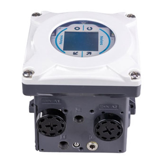
- Page 1 Intelligent valve controller Installation, Maintenance and Operating Instructions For full information go to our website: www.metso.com/ndx...
-
Page 2: Table Of Contents
TABLE OF CONTENTS GENERAL START UP FOR YOUR SAFETY LOCAL USER INTERFACE (LUI) 1.1 BEFORE YOU BEGIN 12.1 OVERVIEW SAFETY PRECAUTIONS 12.2 LUI - USER ACCESS CONTROL PRODUCT SUMMARY 12.3 CALIBRATION REQUIRED PRIOR TO START 3.1 INTRODUCTION TO NELES® 12.4 MONITORING VIEWS NDX INTELLIGENT VALVE CONTROLLER 12.5 ACTIVE ALERTS 3.2 KEY FEATURES... - Page 3 GENERAL INFO MAINTENANCE MAINTENANCE 14.1 GENERAL SPECIFICATIONS 14.2 ORDERING SPARE PARTS 14.3 REPLACING PARTS 14.3.1 Prestage 14.3.2 Removal of prestage 14.3.3 Installation of prestage 14.3.4 Relay valve LOGISTICS 14.3.5 Removal of relay valve 14.3.6 Installation of relay valve 14.3.7 Local User Interface 14.3.8 Electronics module 14.4 REPLACING OPTIONS 14.4.1 Pressure Gauge Block...
- Page 4 These instructions provide information about the safe handling and operation of the intelligent valve controller. If you require additional assistance, please contact the manufacturer or manufacturer’s representative. Addresses and phone numbers are printed on the back cover. See also www.metso.com/valves for the latest documentation. SAVE THESE INSTRUCTIONS! Subject to change without notice.
-
Page 5: For Your Safety
Addresses and phone numbers are printed on the back cover. See also www.metso.com/NDX for the latest documentation. SAVE THESE INSTRUCTIONS FOR LATER USE! BEFORE YOU BEGIN Do not install, operate or maintain intelligent valve con... -
Page 6: Safety Precautions
NDX VALVE CONTROLLER SAFETY PRECAUTIONS NOTE Ex WARNING Avoid grounding a welding machine in close Electrostatic charge hazard! proximity to a valve controller. Damage to The cover is nonconductive. Clean with the equipment may result. a damp cloth only! Spark hazard! Protect the aluminum housing from impacts and friction! CAUTION... - Page 7 NDX VALVE CONTROLLER SAFETY PRECAUTIONS Ex d WARNING (NDX Ex d version) Tightening torque for the housing cover screws is 15Nm. Ex d WARNING (NDX Ex d version) Use a cable gland and blind plug with suitable Ex d certification. For ambient temperature over 70 °C / 158 °F use a heat resistant cable and cable gland suitable for at least 92 °C / 196 °F.
-
Page 8: Product Summary
PRODUCT SUMMARY INTRODUCTION TO NELES® NDX INTELLIGENT VALVE CONTROLLER Metso’s Neles NDX is the next generation intelligent valve controller working on all type of control valves and in all industry areas. It guarantees end product quality in all operating conditions with incomparable performance, unique diagnostics, and years of reliable service. -
Page 9: Operation Principle
NDX VALVE CONTROLLER PRODUCT SUMMARY Product reliability • Designed to operate in harsh environmental conditions • Rugged modular design • Excellent temperature characteristics Output stage • Vibration and impact tolerant • IP66/NEMA4X enclosure Pneumatic actuator • Protected against humidity EXH1 •... -
Page 10: Digital Output (Namur)
NDX VALVE CONTROLLER PRODUCT SUMMARY MARKINGS 3.4.2 Digital output (namur) There are up to two configurable namur type digital outputs The valve controller is equipped with three identification (DO). They can be configured to activate based on valve plates. position measurement (as a limit switch) or any device status. Configuration can be done via HART by using Valve Manager (DTM) or EDD. - Page 11 NDX VALVE CONTROLLER PRODUCT SUMMARY Warnings plate Warnings plate includes explosion hazard warnings. Fig. 7 Warnings plate...
-
Page 12: Exploded View
NDX VALVE CONTROLLER PRODUCT SUMMARY EXPLODED VIEW Fig. 8 NDX1510_ exploded view Fig. 9 _NDX_511_exploded_view... - Page 13 NDX VALVE CONTROLLER PRODUCT SUMMARY Fig. 10 NDX_512_ exploded view Linear Magnet Holder Assembly (VD4855) NDX part list Description 1510 _511 _512 Tools Housing assem. Grounding screw, ext. SLOT8 Grounding screw, int. Cover assem. main * Cover screw Cover screw ...
-
Page 14: Tools
NDX VALVE CONTROLLER PRODUCT SUMMARY TOOLS Following tools are needed for the product installation and maintenance: TX 7 3 mm 3 mm 13 mm and 21/22 mm with linear actuators. TX 8 8 mm 5 mm 8 mm and 24 mm with rotary actuators. TX 10 6 mm TX 20... -
Page 15: Specifications
NDX VALVE CONTROLLER TECHNICAL DESCRIPTION General Pneumatics Loop powered 420 mA, no external power supply required. Supply Pressure: 1.4–8 bar / 20–116 psi (single Suitable for linear and rotary valves. acting) Actuator connections in accordance with VDI/VDE 3845 and IEC 2.0–8 bar / 29–116 psi 605346 standards. -
Page 16: Approvals
T6: 40 °C ...+50 °C Class I, Zone 2 AEx nA IIC T4/T5/T6 Gc DO loop: Ui ≤ 16 V CSA C22.2 No. 21317/ UL 121201 CAN/CSAC22.2 No. 60079 15:16 UL 6007915:13 NOTE See latest uptodate information of approvals on metso.com/ndx... -
Page 17: Logistics
NDX VALVE CONTROLLER TRANSPORTATION AND STORAGE The valve controller is a sophisticated instrument and it shall be handled with care. Products must be stored in a clean, dry environment. Device is delivered in IP67 packaging for storage and transportation. • Check the controller for any damage that may have occurred during transportation. -
Page 18: Recycling And Disposal
NDX VALVE CONTROLLER RECYCLING AND DISPOSAL Most valve controller parts can be recycled if sorted accord ing to material. A valve controller may also be returned to manufacturer for recycling and disposal. -
Page 19: Mounting
NDX VALVE CONTROLLER LINEAR MOUNTING Installation to Neles Globe Mount the bracket to the actuator, leaving the screws loose. NOTE The enclosure of NDX meets the IP66 pro tection class according to EN 60529. Cable entry needs to be plugged according to IP66 and it is not allowed to mount NDX in a po... - Page 20 NDX VALVE CONTROLLER LINEAR MOUNTING Bracket Orientation Table – Neles Globe Neles Actuator Size Stroke (mm) Bracket Model / Orientation Fig. 16 Tighten the bracket screws from step 2. Remove the magnet alignment tool. 20, 40 Mount the NDX to the bracket. 40, 50, 60 80, 90 Fig.
-
Page 21: Installation To Iec Mounting Face
NDX VALVE CONTROLLER LINEAR MOUNTING Installation to IEC mounting face Mount the IEC bracket to the actuator, leaving the screws loose. The following mounting brackets are designed for linear Mount the magnet alignment tool (magnetically) to actuators using the IEC 605346 interface. These kits include the magnet bracket. - Page 22 NDX VALVE CONTROLLER LINEAR MOUNTING Adjust the position of the magnet bracket (and the When the magnet moves smoothly in the magnet IEC bracket) so that the magnet slides smoothly in alignment tool, that automatically defines the correct the magnet alignment tool groove. alignment and distance from the device position Tighten the magnet bracket screws.
-
Page 23: Installation To Any Linear Actuator
Installation to any linear actuator NOTE NDX can be easily installed to any linear actuator when the Use only Metso original magnets. following installation rules are followed. In order to guar Bracket and fixing bolt material should have antee the best possible position measurement accuracy, low magnetic permeability (e.g. - Page 24 NDX VALVE CONTROLLER LINEAR MOUNTING The distance between the magnet and the device bottom shall be 4.5 mm with +/ 3 mm tolerance 4.5 +/ 3 [mm] (1.5 7.5 mm). Check that following magnet alignment require ments are not exceeded. Figure 24 shows the exclusion zone.
-
Page 25: Rotary Mounting
NDX VALVE CONTROLLER ROTARY MOUNTING Rotary mounting is designed according to VDI/VDE 3845 Magnet will be tightened as tight as 4 Nm. From the oper interface. ation point of view magnet can be in any position so there is no adjustment needed. NOTE The enclosure of NDX meets the IP66 pro... -
Page 26: Installation To Any Rotary Actuator
NDX and position feedback magnet must be positioned according to the following guidelines. NOTE Use only Metso original magnets. Bracket and fixing bolt material should have low magnetic permeability (e.g. AISI316 or aluminium). Aim for small mechanical clearance, but avoid contact. -
Page 27: Pneumatics Piping
NDX VALVE CONTROLLER PNEUMATICS PIPING NDX pneumatics piping Actuator Housing Exhaust Exhaust 8 mm 6 mm 3/8” NPT 3/8” NPT Actuator Pressure 1/4” NPT Supply Pressure (1.48 bar / 20116 psi) Media: Air, nitrogen or sweet natural gas 1/4” NPT Fig. 29 NDX1510_ piping Housing Actuator Exhaust... - Page 28 NDX VALVE CONTROLLER PNEUMATICS PIPING Check valve on supply pressure port Fig. 31 Check valve on supply pressure port (S) Check valve on supply pressure port (S) is used on double CAUTION acting version of NDX (NDX251_) only. If double acting version of NDX (NDX251_) is installed on single acting actuator, the check Check valve on supply pressure port (S) shall be used with valve must be removed.
- Page 29 NDX VALVE CONTROLLER PNEUMATICS PIPING Pneumatics piping when pressure gauge block is installed Fig. 32 NOTE NOTE Placement and distances between exhaust When NDX251_ is used with single acting and pressure channels are different than with actuator, one of the pneumatic ports (I or II) out the pressure gauge block.
- Page 30 NDX VALVE CONTROLLER PNEUMATICS PIPING Exhaust covers installed Fig. 33 NDX1510_exhaust covers Fig. 34 NDX_511_ and NDX_512_exhaust covers NOTE NOTE (NDX1510_) When mounting the pneumatic connectors, Exhaust covers are different for Exh I and the exhaust cover may need to be removed Exh II and shall not be mixed.
- Page 31 NDX VALVE CONTROLLER PNEUMATICS PIPING DOUBLE-ACTING ACUATOR 1. Increasing input singnal to open valve (shown) Actuator type: Double acting Positioner fail action: Close Signal direction: Rising Other parameters according to assembly 2. Increasing input signal to close valve (not recommended) Actuator type: Double acting Positioner fail action: Close Signal direction: Falling...
- Page 32 NDX VALVE CONTROLLER PNEUMATICS PIPING Suggested Piping Size Supply Pressure (S) Actuator Pressure (I and II) All actuator types and sizes All actuator types and sizes 10 mm (3/8”) 10 mm (3/8”) Loctite Loctite Fig. 36 NOTE NOTE It is recommended to use 10 mm (3/8”) (inside The stroking times mentioned in the table diameter) supply air and actuator pressure piping.
- Page 33 NDX VALVE CONTROLLER PNEUMATICS PIPING Spring Range and Supply Pressure Table Actuator Type Spring Range Supply Pressure Suggested Neles VD***C 0.8 .. 2.6 bar / 11 .. 37 psi 2.6 bar / 38 psi 3.6 bar / 52 psi 4.0 bar / 58 psi Neles VD***A 0.2 ..
-
Page 34: Electrical Installation
NDX VALVE CONTROLLER ELECTRICAL INSTALLATION 420 mA 3 mm 10 mm (Optional) 2 pc. 1/2” NPT Standard 420 mA M20X1.5 available with adapter Fig. 37 Wiring of NDX1510_ Connector Function Power Source Min. Power Impedance Other 420 mA 3.8 mA, Setpoint / HART 485 Ω... - Page 35 NDX VALVE CONTROLLER ELECTRICAL INSTALLATION HAZARDOUS AREA NONHAZARDOUS AREA Position Transmitter Li 100 μH Exi Barrier Ci 22nF Uout max 28 V Imax 120 mA Iout max 120 mA Umax 28 V Pmax 1 W Pmax 1 W Setpoint Exi Barrier Li 100 μH Uout max 28 V...
-
Page 36: Installation Of Device Options
NDX VALVE CONTROLLER INSTALLATION OF DEVICE OPTIONS 11.1 Pressure Gauge Block installation 5 mm 10 mm Fig. 41 Pressure gauge installation of NDX1510_ 5 mm 10 mm Fig. 42 Pressure gauge installation of NDX_511_ and NDX_512_... - Page 37 NDX VALVE CONTROLLER INSTALLATION OF DEVICE OPTIONS Remove exhaust covers from the device exhaust ports I and II by hand. NOTE Set the gasket onto the pressure gauge block. Remove all temporary transportation plugs with Set the pressure gauge block against to the device 10 mm hexagon wrench just before installing and tighten three screws.
-
Page 38: Start Up
NDX VALVE CONTROLLER LOCAL USER INTERFACE (LUI) Enter menu & select / accept ENTER value to change Move within menus & change values Cancel actions & return up one level DOWN BACK Fig. 43 þ Input Signal Direction þ Positioner Fail Action NOTE þ... -
Page 39: Calibration Required Prior To Start
NDX VALVE CONTROLLER LOCAL USER INTERFACE (LUI) User access can be controlled with following methods: Cover lock (factory default) PIN lock Cover & PIN lock When Cover lock is enabled, detaching the main cover will unlock the LUI for editing. When the cover is reattached, LUI is again locked to read only mode. -
Page 40: Monitoring Views
NDX VALVE CONTROLLER LOCAL USER INTERFACE (LUI) 12.4 Monitoring views Linear Rotary Menu Press the up/down arrow buttons to scroll through the main measurement displays and to view any active events. User can select one of these main displays which will stay on the LUI. -
Page 41: Exceptions
NDX VALVE CONTROLLER LOCAL USER INTERFACE (LUI) POS > 999 % or 12.6 Exceptions sensor broken If position measurement goes out of range or fails, position indicator shows on the LUI. 12.7 Remote actions When calibration or offline test is started remotely (i.e. from DTM), there is a warning on the LUI before the valve starts to move. -
Page 42: Guided Start-Up
NDX VALVE CONTROLLER LOCAL USER INTERFACE (LUI) 12.8.1 Guided start-up When Guided Startup is highlighted press to enter the menu. Press to see the parameter options, then use Guided startup offers a fast and easy way to go through all to select the correct value and press to accept the new necessary steps for start up of the device. -
Page 43: Calibration
NDX VALVE CONTROLLER LOCAL USER INTERFACE (LUI) 12.8.2 Calibration To open the main menu, press menu button (if PIN code is 1-point calibration If Valve type = Rotary If Valve type = Linear activated, PIN code will be asked when something is tried to change). -
Page 44: Parameters
NDX VALVE CONTROLLER LOCAL USER INTERFACE (LUI) Automatic calibration After selecting the Automatic calibration from the menu, press enter. There is a warning about automatically moving valve before calibration will start. If it is safe to continue, press enter and arrow keys at the same time as shown in the display. - Page 45 NDX VALVE CONTROLLER LOCAL USER INTERFACE (LUI) Increasing input signal closes valve Increasing input signal opens valve Valve series POSITION Valve size D, P, C T5, T25, R, QR QMBV QMBV QT25 SOFT Dead angle % 25.5 19.5 ...
- Page 46 NDX VALVE CONTROLLER LOCAL USER INTERFACE (LUI) default), Fast, Aggressive, Max Stability FO, Stable FO, Optimum FO, Fast FO, Aggressive FO. þ Max Stability: Slowest response to signal changes and no overshoot. Trying to keep the valve position as stable as possible. Stable: Fairly slow response to signal changes and no overshoot.
- Page 47 NDX VALVE CONTROLLER LOCAL USER INTERFACE (LUI) þ Following instrumentation options can be selected: None, Booster, QEV, Booster&QEV The default value is None meaning that there are no additional instrumentation in the valve assembly. If there is a volume booster in the assembly, select Booster.
- Page 48 NDX VALVE CONTROLLER LOCAL USER INTERFACE (LUI) Symmetry • þ This parameter defines the symmetry for the valve opening and closing speeds þ The range for the symmetry parameter value is 0.0 ... 2.0 þ Once Symmetry parameter is selected, press enter to edit the parameter þ...
-
Page 49: Linearization
NDX VALVE CONTROLLER LOCAL USER INTERFACE (LUI) Cycle main views • þ It is possible make device to scroll automatically three main views on the display. þ If Cycle main views is disabled (default setting), then view which is selected by the user, will remain on the display. -
Page 50: Manual Control
NDX VALVE CONTROLLER LOCAL USER INTERFACE (LUI) 12.8.5 Manual control Position control During this mode the valve position may be controlled manually by using the arrow keys. The manual control starts from the current position of the valve after the manual mode is activated. Valve position may jump when going back to auto mode and device starts to follow setpoint. -
Page 51: Operation
Introduction to DTM 13.1.3 For More Information on the FDT Standard Metso Device Type Manager (DTM) is part of an open solu For more information on the FDT standard, you can refer tion for field device management that provides the best... -
Page 52: User Interface Information
NDX VALVE CONTROLLER DEVICE TYPE MANAGER (DTM) 13.3 User Interface Information Figure below shows the DTM user interface. The user inter face elements indicated by numbers are explained in more detail below. Fig. 51 Refresh button reloads the active view from the Parameter set state. -
Page 53: Using Dtm
DTM language and save data folder. The configurator util In this same menu should be a section called “Additional ity can be started from Start menu → All Programs → Metso Functions”. Under the Additional Functions menu are the Device DTM →... -
Page 54: Parameterize Online
NDX VALVE CONTROLLER DEVICE TYPE MANAGER (DTM) 13.5.2 Parameterize Online 13.5.2.2 Device Information This window gives tools for quickly checking the state of the device, perform guided commissioning process and configure the behavior of the device. 13.5.2.1 Performance Fig. 56 Device information view contains information on valve controller, actuator and valve. -
Page 55: 13.5.2.3 Commissioning
NDX VALVE CONTROLLER DEVICE TYPE MANAGER (DTM) 13.5.2.3 Commissioning 13.5.2.4 Status Configuration DTM has a guided startup to help you with commissioning Available statuses can be either disabled or classified to a of the device. certain NAMUR class in Status Configuration view. Status limits and current value is shown in the same view when applicable. - Page 56 NDX VALVE CONTROLLER DEVICE TYPE MANAGER (DTM) Control Performance Diagnostics Status Related events in the event log Status description Proposed actions Default NAMUR classification Travel Ratio Limit Travel Ratio Limit Exceeded Valve travel/valve Check if process conditions have changed. Info Exceeded reversals Evaluate if limit is correctly set.
- Page 57 NDX VALVE CONTROLLER DEVICE TYPE MANAGER (DTM) Status Related events in the event log Status description Proposed actions Default NAMUR classification Partial Stroke Test Partial Stroke test started Device functional test Check the test result from DTM/EDD Event Function Running is running.
- Page 58 NDX VALVE CONTROLLER DEVICE TYPE MANAGER (DTM) Status Related events in the event log Status description Proposed actions Default NAMUR classification Missing Position Feed Position Feedback Magnet Position feedback Check magnet installation. Calibrate the Failure back Magnet Missing magnet is missing. device.
- Page 59 NDX VALVE CONTROLLER DEVICE TYPE MANAGER (DTM) Valve Diagnostics Status Related events in Status description Proposed actions Default NAMUR the event log classification Total Valve Travel Limit Total valve travel limit exceeded Userdefined limit Review the device performance. If perfor Maintenance Exceeded exceeded.
- Page 60 NDX VALVE CONTROLLER DEVICE TYPE MANAGER (DTM) Operating Condition Diagnostics Status Related events in Status description Proposed actions Default NAMUR the event log classification Control Ratio Limit Control Ratio Limit Exceeded Valve reversals/Set Check if process conditions have changed. Info Exceeded point reversals Evaluate if limit is correctly set.
- Page 61 NDX VALVE CONTROLLER DEVICE TYPE MANAGER (DTM) Status limits are listed and explained in following tables. Control Performance Diagnostics Limits Parameter name Description Default value Limits/options Set travel ratio alert limit. Travel Ratio Limit If a value is lower than the limit, a 0100 % status is activated for the device and an event is generated.
- Page 62 NDX VALVE CONTROLLER DEVICE TYPE MANAGER (DTM) Valve Diagnostics Limits Parameter name Description Default value Limits/options Total Valve Travel Limit Set the Total Valve Travel alert limit. 1000 0000 010 0000 0000 Counter increases by 1 whenever the valve has travelled one full stroke, or 100 % of the valve movement.
- Page 63 NDX VALVE CONTROLLER DEVICE TYPE MANAGER (DTM) Operating Condition Diagnostics Limits Parameter name Description Default value Limits/options Control Ratio Limit Set control ratio alert limit. 1100 If a value exceeds the limit or falls below 1/limit, a status is activated for the device and an event is generated. Temperature Above High Limit Set temperature high alert limit.
- Page 64 NDX VALVE CONTROLLER DEVICE TYPE MANAGER (DTM) All parameters This view lists all configurable device parameters. In offline mode, All parameters view is the view, which is opened from the frame application “Offline parameterize” menu option for parameterizing the device beforehand before going to online mode or before the device is available.
- Page 65 NDX VALVE CONTROLLER DEVICE TYPE MANAGER (DTM) Performance Level If you want to change the tuning of the valve position control, Optimum Maximum Stability performance level selection is available. Stable Max Stability: Slowest response to signal changes and no over shoot.
- Page 66 NDX VALVE CONTROLLER DEVICE TYPE MANAGER (DTM) Bypass Signal Modifications Defines whether Signal Modification parameters are applied or Yes (Signal modifica not. tions are discarded.) Affects following parameters: • Signal direction No (Signal modifica • Cutoff closed tions are applied to •...
- Page 67 NDX VALVE CONTROLLER DEVICE TYPE MANAGER (DTM) Localization Parameter name Description Default value Limits/options Local User Interface Language Select the desired language to be used in local user interface. English English Chinese Spanish Italian French Korean German Turkish Dutch Portuguese Device Temperature Unit Select the desired temperature units for various device vari...
- Page 68 NDX VALVE CONTROLLER DEVICE TYPE MANAGER (DTM) Reset Diagnostics Parameter name Description Default value Limits/options Diagnostics Reseting following diagnostics data is None None possible: Positioner counters Reset Positioner Counters Valve counters Actuator counters Reset Valve Counters Valve position histogram all ...
-
Page 69: Diagnosis
The log file location is determined by Metso Device DTM Configuration utility, which can be found from the Windows Start menu. The default location for the log file is: C:\ProgramData\Metso\ NDX Device DTM\Data. Fig. 63 NOTE 13.5.3.2 Online Valve Signature... -
Page 70: 13.5.3.4 Offline Testing
NDX VALVE CONTROLLER DEVICE TYPE MANAGER (DTM) Most of the device statuses also create corresponding events in the event log. These are listed in chapter Para meterize Online/Status Configuration. In addition there are a few events which are only logged in the event history. -
Page 71: 13.5.3.6 Counters
NDX VALVE CONTROLLER DEVICE TYPE MANAGER (DTM) 13.5.3.6 Counters HART Diagnostics Parameter name Description Total Total HART messages received Messages In Total Total HART messages sent Messages Out HART Com HART communication error rate in percentage munication during last hour Error Rate during last hour... -
Page 72: 13.5.3.8 Valve Position Histogram
NDX VALVE CONTROLLER DEVICE TYPE MANAGER (DTM) Advanced Diagnostics Valve position histogram trend is especially useful when optimizing plant operation or replacing old control valves. Following trends are available in advance diagnostics ver • If valve operation point is 8090 % most of the sion of NDX: time, then the valve could be too small for current •... -
Page 73: Maintenance
(includes H149508 and H137059 assembly) H149528 PNEUMATIC SET for NDX2512_ (includes H149508 and H149515 assembly) NDX valve controller includes following interchangeable ELECTRONICS MODULE: Contact Metso NDX valve controller modules: Relay valve Prestage unit 14.3... -
Page 74: Installation Of Prestage
(Disconnect the supply and actuator piping if device is needed to remove). © Metso 2015 • Loosen the prestage cover screws and remove the prestage cover. (Fig. 78) •... -
Page 75: Relay Valve
NDX VALVE CONTROLLER MAINTENANCE Standard and explosion proof version (NDX_511_ and NDX_512_): • TX20, TX7, TX8, PH2 (NDX_511_) or HEX6 (NDX_512_) • Press the prestage into place. Press in the marked positions mildly by hand. Do not use excessive force as this may indicate the prestage shaft is misaligned or the o ring is not lubed. -
Page 76: Installation Of Relay Valve
NDX VALVE CONTROLLER MAINTENANCE NOTE WARNING Do not use any tools to install the relay valve. It It is recommended to replace both the pre stage and the relay valve at the same time. can be pushed in place by hand. •... -
Page 77: Local User Interface
NDX VALVE CONTROLLER MAINTENANCE 14.3.7 Local User Interface HEX6 Fig. 88 NDX1510_ Fig. 89 NDX_511_ and NDX_512_ Tools for NDX1510_: PH2, TX7 14.3.8 Electronics module Tools for NDX_511_: PH2, TX7, TX8 Tools for NDX_512_: HEX6, TX7, TX8 • Remove the main cover by loosening 4 screws. •... - Page 78 NDX VALVE CONTROLLER MAINTENANCE • Remove the device from the actuator mounting bracket if there is limited working space in front of the prestage cover (Disconnect the supply and actuator piping if device is needed to remove). • Remove the main cover by loosening 4 screws. Fig.
-
Page 79: Replacing Options
NDX VALVE CONTROLLER MAINTENANCE 14.4 REPLACING OPTIONS 14.4.1 Pressure Gauge Block Follow instructions in chapter 11.1 Pressure Gauge Block installation. Fig. 96 NDX_511_ and NDX_512_ Fig. 97 Pressure sensors on the electronics module of NDX_510_. NOTE There are pressure sensors on the electronics module. -
Page 80: Dimensions
NDX VALVE CONTROLLER DIMENSION DRAWINGS 15.1 NDX1510 LINEAR APPLICATION ROTARY APPLICATION Fig. 98... -
Page 81: Ndx_511
NDX VALVE CONTROLLER DIMENSION DRAWINGS 15.2 NDX_511_ Fig. 99... -
Page 82: Ndx_512
NDX VALVE CONTROLLER DIMENSION DRAWINGS 15.3 NDX_512_ Tightening torque 15 Nm Fig. 100... -
Page 83: And Rotary Actuators
NDX VALVE CONTROLLER DIMENSION DRAWINGS 15.4 POSITION FEEDBACK MAGNETS FOR LINEAR AND ROTARY ACTUATORS Fig. 101 NDX1510_ 15.5 PRESSURE GAUGE BLOCK NDX1510_ Fig. 102 NDX1510_... - Page 84 NDX VALVE CONTROLLER DIMENSION DRAWINGS Fig. 103 NDX_511_ Fig. 104 NDX_512_...
-
Page 85: Ec Declaration Of Conformity
NDX VALVE CONTROLLER EC DECLARATION OF CONFORMITY Manufacturer: Metso Flow Control Oy Vanha Porvoontie 229 FI01380 Vantaa Finland Product: NELES® NDX INTELLIGENT VALVE CONTROLLER Approvals: Type Approval EC Type examination Certificate ATEX II 1 G Ex ia IIC T6...T4 Ga EESF 18 ATEX 014X ATEX II 1 D Ex ia IIIC T85 °C...T115 °C Da... -
Page 86: How To Order Intelligent Valve Controller Ndx
NDX VALVE CONTROLLER HOW TO ORDER INTELLIGENT VALVE CONTROLLER NDX 1. sign PRODUCT GROUP Intelligent Valve Controller Series NDX 2. sign PNEUMATIC ACTION Single Acting Double Acting Applicable to 5. sign “1” or “2” 3. sign PNEUMATIC CAPACITY Normal Capacity (80 Nm 4. - Page 87 NDX VALVE CONTROLLER HOW TO ORDER INTELLIGENT VALVE CONTROLLER NDX 9. sign APPROVALS FOR HAZARDOUS AREAS (1/2) cCSAus certifications: Class I, Division 1, Groups A, B, C, and D; T4/T5/T6 Ex ia IIC T4/T5/T6 Ga Class I, Zone 0 AEx ia IIC T4/T5/T6 Ga Class I, Division 2, Groups A, B, C, and D;...
- Page 88 NDX VALVE CONTROLLER Metso Flow Control Inc. Europe,Vanha Porvoontie 229, P.O. Box 304, FI-01301 Vantaa, Finland. Tel. +358 20 483 150. Fax +358 20 483 151 North America, 44 Bowditch Drive, P.O. Box 8044, Shrewsbury, M A 01545, USA. Tel. +1 508 852 0200. Fax +1 508 852 8172 South America, Av.
Need help?
Do you have a question about the NELES NDX Series and is the answer not in the manual?
Questions and answers