Advertisement
Water level control for overflow collecting tank
The
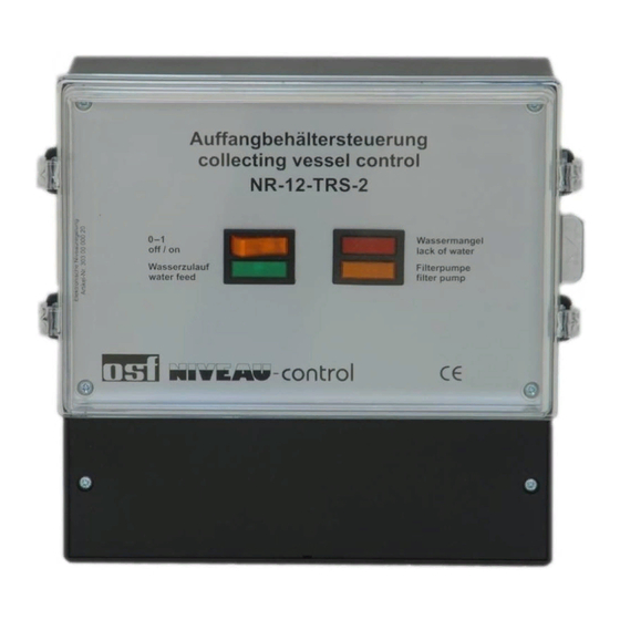
NR-12-TRS-2 collection reservoir control system is a technically high-quality product which can only
correctly fulfil its function if it has been connected and assembled in accordance with the instructions and if this
operating manual is followed. The
overflow channels. It is constructed with integrated circuitry and consists of:
The submerged electrodes do not cause any electrolyte formation in the water because they are operated with
alternating current. The electrode cables can be extended up to 20 m (min. 1.5mm
balancing. The electronic circuitry has been specially developed for overflow collection reservoirs. Wave
movements do not cause direct switching processes due to special circuitry in order to avoid switching cycles
which may be too short.
The submerged electrodes are operated using non-hazardous safety low voltage. The controller itself has been
designed to comply with the currently applicable German VDE and CE regulations.
Control system:
Dimensions:
Operational voltage:
Control system power consumption:
Switching capacity:
Protection class:
Submerged electrodes:
Dimensions:
Cable length:
Operational voltage:
*
See also connection plan.
The controller must be installed in accordance with its protection class. Before opening the housing, the
device must be switched voltage-free using a multi-pole main switch with a contact opening distance of
at least 3 mm. This main switch must be integrated in the on-site installation. It is imperative that you
observe the throughflow direction (arrow direction) indicated on the solenoid valve.
Depending on the swimming pool design, it is possible that rainwater raises the water level in open-air pools and
activates the "forced switching" function. If this operating behaviour is not required, "forced switching ON"
(terminal 8) can be disconnected.
Installation and operating manual
Art. No. 3030000020 (without solenoid valve)
Function:
NR-12-TRS-2 is particularly suitable for use in swimming pools with
electronic controller
submerged electrodes (option)
Specifications:
Installation
Use in open-air pools:
2
) without requiring electronics
220mm x 219mm x 100mm
230V/50Hz
ca. 7VA
max. 1.1kW (AC3)
IP 40
ø24mm x 134mm
3m
12V
:
*
Advertisement
Table of Contents

Related Manuals for OSF NR-12-TRS-2


Summary of Contents for OSF NR-12-TRS-2
- Page 1 Art. No. 3030000020 (without solenoid valve) Function: NR-12-TRS-2 collection reservoir control system is a technically high-quality product which can only correctly fulfil its function if it has been connected and assembled in accordance with the instructions and if this operating manual is followed. The NR-12-TRS-2 is particularly suitable for use in swimming pools with overflow channels.
-
Page 2: Electrical Power Supply
Operating manual NR-12-TRS-2 Page: 2 Installing the submerged electrodes: submerged electrodes are supplied as series with waterproof and ozone-proof special cables. The tensile strength of the cable is sufficient for hanging the electrodes from the special cable in the overflow collection reservoir, and it is also possible for individual electrodes to touch each other. -
Page 3: Functional Information
All other submerged electrodes are necessary for control system function and may not be omitted or bypassed. Functional information: NR-12-TRS-2 collection reservoir control system has the following functions: Water level regulation. Once the water level falls below the "solenoid valve OPEN" submerged electrode due to water losses in the swimming pool, e.g. - Page 4 Operating manual NR-12-TRS-2 Page: 4 Device setting facilities: The control system includes 4 DIP switches and 2 trimmers which can be used to set additional control system functions. Trimmer 1 Time limitation Solenoid valve DIP switch Trimmer 2 Time limitation...
- Page 5 Operating manual NR-12-TRS-2 Page: 5 DIP 3: Forced switching works without time limitation. When the water level reaches the "forced switching" electrode, the pump (K2) is switched on. It is only switched on again once the water level has sunk below the maximum operating level.
-
Page 6: Service Terminal
Operating manual NR-12-TRS-2 Page: 6 Service terminal: There is a connecting plug inside the control unit which can be used to connect the service terminal. Socket for service terminal The service terminal is used to display the level regulation operating status clearly in order to help in possible troubleshooting. - Page 7 Operating manual NR-12-TRS-2 Page: 7 Installation instructions solenoid valve The piping system must be cleaned before the valve installation, because dirt will malfunction. If necessary, a strainer should be mounted in front of the valve inlet. Mechanically clamping the valve housing, for example for non-aligned pipes or improper sealing material is to be avoided.
- Page 8 Operating manual NR-12-TRS-2 Page: 8...
Need help?
Do you have a question about the NR-12-TRS-2 and is the answer not in the manual?
Questions and answers