Table of Contents
Advertisement
Advertisement
Table of Contents

Summary of Contents for Linde CiTi One Series
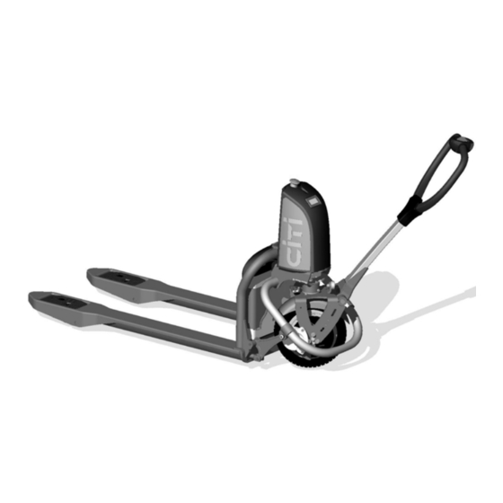
- Page 1 Original instructions Pallet truck CiTi One 1130 801 15 02 EN – 11/2012...
-
Page 3: Table Of Contents
Table of contents Introduction Your truck ............2 Impermissible use . - Page 4 Table of contents Assessing the load ........... 37 Using the battery .
-
Page 5: Introduction
Introduction... -
Page 6: Your Truck
Introduction Your truck Your truck gives you the very best in terms of perfor- mance, safety and driving comfort. It is now up to you to maintain these qualities for a long time to come and to appreciate how to make the very best of them. -
Page 7: Impermissible Use
Introduction Impermissible use Impermissible use The operating company or driver, and not the manufacturer, is liable if the truck is used in a manner that is not permitted. It is not permitted to use the truck: • for taking passengers •... -
Page 8: Symbols Used
Introduction Symbols used Symbols used DANGER NOTE Means that failure to comply can risk the lives of This means that particular attention must be others and/or cause major damage to equipment. paid to the specific technical meaning because this may not be obvious, even to a specialist. WARNING ENVIRONMENT NOTE Means that failure to comply can result in the risk... -
Page 9: Technical Description
Introduction Technical description Technical description CiTi One electric pallet truck Traction motor power: • 0,3 kW (BLDC technology). CiTi One : 500 kg capacity Lift motor power: The CiTi One pallet truck is designed for pallet load handling applications on hard-coated, •... -
Page 10: Legal Requirements For Placing On The Market
Introduction Legal requirements for placing on the market Legal requirements for placing on the market Déclaration Name of manufacturer Address of manufacturer We declare that the machine according to these operating instructions Industrial truck according to these operating instructions Model complies with the most recent version of machinery directive 2006/42/EC. - Page 11 Introduction Legal requirements for placing on the market An independent structural change or addition The EC declaration of conformity must be to the truck can compromise safety, thus carefully stored and made available to the invalidating the EC declaration of conformity. responsible authorities if applicable.
- Page 12 Introduction Legal requirements for placing on the market 1130 801 15 02 EN – 11/2012...
-
Page 13: Safety
Safety... -
Page 14: Safety Regulations
Safety Safety regulations Safety regulations These operating instructions and the VDMA booklet, "Directives concerning the use of industrial trucks in compliance with the specifications and regulations", come with the truck and must be communicated to all those concerned and in particular to personnel responsible for maintenance and driving. -
Page 15: Competent Person
Safety Competent person CAUTION Welding can damage the electrics. Therefore, it is imperative to unplug the battery beforehand and disconnect all connections to printed circuit boards. CAUTION The truck operator must wear safety footwear. Appropriate protective gloves must be worn at all times when changing the battery. - Page 16 Safety Competent person 1130 801 15 02 EN – 11/2012...
-
Page 17: General Views
General views... -
Page 18: Labels
General views Labels Labels CiTi (tiller) label Company label (see next page) Company label (bonnet) Weighing system label Safety label Label PIEK 1130 801 15 02 EN – 11/2012... -
Page 19: Identification Label
General views Identification label Identification label Identification label Battery voltage Manufacturer Minimum battery weight CE symbol (this symbol certifies that the ma- Maximum battery weight chine complies with European regulations Nominal capacity of the truck on industrial trucks) Model Serial number / year Motor rated power Tare weight 1130 801 15 02 EN –... -
Page 20: Truck Modules
General views Truck modules Truck modules Drive wheel On/off button (emergency stop) Brake Tiller Lifting system Display Load wheels Chassis Battery 1130 801 15 02 EN – 11/2012... -
Page 21: Controls
General views Controls Controls Emergency stop button or contact Horn control Safety reverser (belly) Fork lift control Reverse travel Tiller Fork lower control Joystick Forward travel 1130 801 15 02 EN – 11/2012... -
Page 22: Display
General views Display Display 1130 801 15 02 EN – 11/2012... - Page 23 General views Display Designation Message on the display Comment 100% = battery ok 20% = flashing + symbol (7): speed = 50% 10% = flashing + symbol 100% = full charge (7): speed = 50% 10% = the battery must Battery level 10% = flashing = the battery be charged...
-
Page 24: Battery Charge Level
General views Battery charge level Battery charge level Battery charge level (1) is shown on the display. The charge status is displayed on the battery itself by means of a diode (2). To view it, open the battery hood and check the colour of the diode by pressing the push- button (3) continuously for 10 seconds: Battery charge status... -
Page 26: Checks Before First Use
Checks before first use Checks before first use Carried Forward and reverse travel control Lifting and lowering control Emergency stop button Brake operation Operating the alarm horn Operating the safety reversing gear Steering Wheel fastenings Tiller in raised position (neutral) 1130 801 15 02 EN –... -
Page 27: Operating Instructions
Operating instructions Operating instructions The CiTi One is designed for indoor and WARNING outdoor use in non-hazardous environments Always adapt your driving to the ground condi- where the air humidity is less than 95%. tions (uneven surfaces etc.), particularly hazar- dous working areas and the load. -
Page 28: Start-Up
Start-up Start-up Pull the button (A) to start the truck. The display starts up (B). NOTE If the truck has not been used for some time, position the button in the holding fixture, then turn to the right. Standby If the joystick has not been activated for 10 minutes, the truck switches to standby... -
Page 29: Functions Of The On/Off Button (Emergency Stop)
Functions of the on/off button (emergency stop) Functions of the on/off button (emergency stop) A Removing or inserting the button Position the button correctly (holding fixture). B Removing the button (safety) Remove the button when the truck is no longer in use. -
Page 30: Forward Travel/Reverse Travel
Forward travel/reverse travel Forward travel/reverse travel On a pallet truck, the conventional controls for the drive direction are: • Forward gear: (5) - Tiller direction • Reverse gear: (6) - Fork arm direction Forward gear (tiller direction) Tilt the tiller (1) 1130 801 15 02 EN –... - Page 31 Forward travel/reverse travel Pull the joystick (2) towards you (A) with your thumb. Reverse gear (fork arm direction) Tilt the tiller (1) Push the joystick (2) towards the fork arms (B) with your thumb. 1130 801 15 02 EN – 11/2012...
-
Page 32: Safety Devices
Safety devices Safety devices Emergency stop button Press button (3). Safety reverser Press button (4). Horn Press button (5). 1130 801 15 02 EN – 11/2012... -
Page 33: Use On A Slope
Use on a slope Use on a slope NOTE Incorrect use of the truck on a slope is not recommended. It places particular stress on the traction motor, brakes and battery. Slopes must always be approached with great caution: Never attempt a slope whose gradient is greater than that specified in the truck’s datasheet. - Page 34 Use on a slope Tilt the tiller into the driving position. Release the joystick to apply the parking brake. Characteristics: Percentage Load 500 kg 8% maximum 1130 801 15 02 EN – 11/2012...
-
Page 35: Recommended Maximum Obstacle Clearance
Recommended maximum obstacle clearance Recommended maximum obstacle clearance CAUTION Do not travel with excessive speed when overriding kerbs and other obstacles. Reduce your speed accordingly. When climbing a kerb always travel with the forks trailing. Recommended maximum obstacle clear- ance with a speed of less than 2 km/h Direction: tiller Load in kg height in mm... -
Page 36: Braking System
Braking system Braking system Braking by reversing the direction of travel Braking can be achieved by reversing the direction of travel: Move the joystick in the opposite direction until the truck comes to a stop. Then release the joystick. Automatic braking ... -
Page 37: Raising
Raising Raising Fork arms lifting Move the joystick (7) to the right (A) Fork arms lowering Move the joystick (7) to the left (B) 1130 801 15 02 EN – 11/2012... -
Page 38: Working With Loads
Working with loads Working with loads DANGER Safety footwear must be worn. CAUTION Transporting people is strictly prohibited. CAUTION Be careful not to touch adjacent loads or loads positioned at the side or in front of the load being handled. Loads must be arranged so that they are aligned with a narrow space between them to prevent them from catching. - Page 39 Working with loads Picking up a load Approach the load carefully. Lower the load arms so that they can easily be inserted into the pallet. Insert the load arms under the load. If the load is shorter than the load arms, position it so that the end of the load over- hangs the end of the load arms by a few centimetres, in order to avoid hooking the...
- Page 40 Working with loads Setting a load down on the ground Carefully drive the machine to the required location. Carefully move the load into the unloading area. Lower the load until the load arms are free. Withdraw the machine in a straight line. ...
-
Page 41: Assessing The Load
Assessing the load Assessing the load The truck is fitted with a system for weighing pallets (or other containers with the same dimensions). The system has a tolerance of ±25 kg for loads up to 400 kg, provided the load is correctly positioned (see below). 1.1 Load positioning A) The load measured must be correctly positioned on the pallet (centre of gravity in... - Page 42 Assessing the load 1.3 Checking the load assessment system This check must be carried out regularly during the truck’s first hours of operation and after any use that may have resulted in exceptional mechanical stress (e.g. a fall from a rear flap or movement over obstacles with heavy loads) To carry out this operation: ...
- Page 43 Assessing the load Once it has been reset to zero, 999 will be shown on the screen (3). NOTE The "Resetting to zero" menu is automatically deactivated: - If the operator waits too long after pressing the button to perform the first lift - If the operator waits too long between two lifts 1.5 Display Message...
-
Page 44: Using The Battery
Using the battery Using the battery Installation and first use CAUTION Use the power supply with a constant NEVER: current. Immerse the battery. Use a power supply that is not suitable for charging Check that the voltage printed on the label the battery. -
Page 45: Relative Battery Charge Status And Periodic Discharge
Relative battery charge status and periodic discharge Relative battery charge status and periodic discharge The relative battery charge status indicates NOTE the battery capacity as a percentage. The last battery discharge value measured The percentage is calculated in comparison is updated if a complete cycle is initiated (full to the remaining capacity during the last charge + full discharge). -
Page 46: Storing The Battery
Storing the battery Storing the battery It is recommended that the battery is stored connected to a charging current, in order to maintain the battery charge status via a maintenance charge. If the battery cannot be stored connected to a charging current, it must be disconnected and stored in a dry place at a constant tempera- ture. -
Page 47: Slinging
Slinging Slinging WARNING Risk of serious injury and/or serious damage to equipment. Use hooks and a hoist of sufficient capacity and protect all parts coming into contact with the lifting device. Weight of machine (with battery): see technical specifications. Remove the load before slinging the truck. ... -
Page 48: Towing
Towing Towing CAUTION Deterioration or destruction of the equipment. Do not tow the truck by the control unit (tiller). Setting the load down in the event of a breakdown If the truck breaks down with the load in the raised position, use the following procedure: ... - Page 49 Towing Assemble the screw (2) and button (3) assembly and place the entire object inside the handle (1) as shown The brake can then be released by turning the assembly in the direction shown Transporting the machine If the truck has to be transported, make sure that it is properly chocked and protected against bad weather.
- Page 50 Towing 1130 801 15 02 EN – 11/2012...
-
Page 51: Maintenance
Maintenance... -
Page 52: Specified Use (Citi Application)
Maintenance Specified use (CiTi application) Specified use (CiTi application) Maximum load (Kg) Value Lift motor capacity S3: 5% Traction motor capacity S2: 20 minutes Maximum obstacle clearance speed (km/h) Recommended obstacle clearance height (mm) Recommended obstacle clearance height (mm) Recommended obstacle clearance height (mm) The batteries, wheels and tires are wearing parts. -
Page 53: Opening The Battery Hood
Maintenance Opening the battery hood Opening the battery hood Position the button (1) in the holding fixture (2) then turn to the right (a quarter-turn). NOTE Observe the direction of the button. Disconnecting the battery connector Open the battery cover. ... -
Page 54: Recharging The Battery With The Charger
Maintenance Recharging the battery with the charger Recharging the battery with the charger Open the battery cover. Unplug the battery connector Remove the battery using the handle. Place the battery near a power socket. Connect the charger cord to the battery and connect the charger power plug to the power socket. -
Page 55: Main Fuse
Maintenance Main fuse The battery is operational; the charge status is greater than Yellow then green alternately Equalisation charging The current is reduced during this stage in order to continue charging the different elements equally. Equalisation charging is complete; the battery can supply 100% of its capacity Maintenance charging Green... - Page 56 Maintenance Main fuse 1130 801 15 02 EN – 11/2012...
-
Page 57: Technical Specification
Technical specification... -
Page 58: Technical Datasheet
Technical specification Technical datasheet Technical datasheet 1130 801 15 02 EN – 11/2012... - Page 59 Technical specification Technical datasheet DESIGNATION 1.2 Model type CiTi One 1150 CiTi One 950 Method of propulsion: battery, battery diesel, petrol, LPG, mains power Driving: manual, pedestrian, Pedestrian standing, seated, order picking 1.5 Nominal capacity Q (kg) 1.6 Centre of gravity C (mm) Distance from the load wheel axle to the front of the forks (±5...
- Page 60 Technical specification Technical datasheet DIMENSIONS CiTi One 1150 CiTi One 950 4.4 Lift (± 5 mm) H3 (mm) Height of the operating device in H14 (mm) 650 / 1170 driving position, min / max. Height of the forks in the lower position H13 (mm) 4.15 (±...
- Page 61 Technical specification Technical datasheet DRIVE CiTi One Battery voltage and capacity 6.43 V/Ah 36 / 15 Ah (discharge in 5 h) 6.5 Battery weight 5 Ah / 9 Ah / 15 Ah 6.4 / 7 / 10.5 Energy consumption according to 0.06 standardised VDI 2198 cycle MISCELLANEOUS...
- Page 62 Technical specification Technical datasheet 1130 801 15 02 EN – 11/2012...
-
Page 63: Diagrams
Diagrams... -
Page 64: Circuit Diagram
Diagrams Circuit diagram Circuit diagram BK 4² RD 4² RD 4² GY 0,75² BU 0,75² BN 0.75² BN 0,75² WH 0.75² BN 2² GN 0.75² BK 2² GY 2² YE 0,75² BK 0,75² BN 0.75² BN 0.75² RD 2² BK 2² BN 0.14²... - Page 65 Diagrams Circuit diagram Control module (travel, lift, horn) (19-47) Traction motor connector (26, 27, 28) Traction and lift controller (LAC) (17-80) Setting connector for controller control (22-31) Accelerator potentiometer (36-40) Tiller foot connector (24-28) Lower fork sensor (53) Control module connector (30-52) Upper fork sensor (55) Lift controller connector (40-42) Lift potentiometer (42-46)
- Page 66 Diagrams Circuit diagram 1130 801 15 02 EN – 11/2012...
- Page 67 Index Ascending slopes ....29 Horn Assessing the load ....37 Safety devices .
- Page 68 Index Technical datasheet ....54 Warnings ......4 Technical description .
- Page 70 1130 801 15 02 EN – 11/2012...
Need help?
Do you have a question about the CiTi One Series and is the answer not in the manual?
Questions and answers