Table of Contents
Advertisement
ASSEMBLY, INSTALLATION, CARE, MAINTENANCE AND USER INSTRUCTIONS
This product is designed to be used simultaneously by up to 6 children between the ages 3 to 8.
Maximum weight of each user is 100lbs(45kg). Combined weight of all users must not exceed
600lbs(272kg).
Carefully read this entire instruction manual before you start to assemble or use this swing set.
You must follow all instructions and warnings while using this equipment.
Constant adult supervision is required during use.
Do not use this swing set on hard packed soil, concrete, or any kind of hard surface.
This equipment must be anchored (anchors not included). You should consult your local contractor
regarding the best way to anchor the product in your location of installation.
Assembly requires at least two adults.
For Customer Service, please call 1-866-370-2131 or visit
LEVEL 20, PARKVIEW CENTRE, 7 LAU LI STREET, CAUSEWAY BAY, HONG KONG
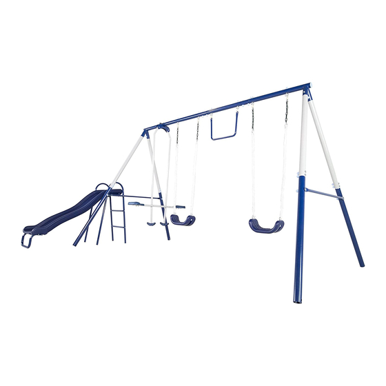
MODEL # MSC-4510
Arcadia Metal Swing Set
OWNER'S MANUAL
FOR RESIDENTIALUSEONLY
WARNING
Save this instruction manual for future reference
Monday – Friday 9:00 AM – 5:00 PM Eastern Time
Sportspower Ltd.
www.sportspowerltd.net
Advertisement
Table of Contents

Related Manuals for SPORTSPOWER Arcadia


Summary of Contents for SPORTSPOWER Arcadia
- Page 1 MODEL # MSC-4510 Arcadia Metal Swing Set OWNER’S MANUAL ASSEMBLY, INSTALLATION, CARE, MAINTENANCE AND USER INSTRUCTIONS FOR RESIDENTIALUSEONLY WARNING This product is designed to be used simultaneously by up to 6 children between the ages 3 to 8. ...
- Page 2 INTRODUCTION Dear Valued Customer, Congratulations on your Sportspower play set purchase! Please read and completely understand the contents of this owner’s manual. This manual contains specific instructions and warnings that must be followed to prevent injuries. This play set is for residential use only. This play set is NOT intended for public or commercial use.
-
Page 3: Table Of Contents
TABLE OF CONTENTS IMPORTANT INSTRUCTIONS AND WARNINGS ........................ 4 IMPORTANT CONSUMER INFORMATION SHEET ......................8 ANCHORING.................................... 9 CARE AND MAINTENANCE CHECKLIST ......................... 11 TOOLS NEEDED ................................... 12 PARTS LIST ................................... 13 ASSEMBLY INSTRUCTIONS .............................. 18 AREA OF INSTALLATION - SWING SET TOP BAR ......................18 AREA OF INSTALLATION - UPPER SIDE LEGS ........................ -
Page 4: Important Instructions And Warnings
IMPORTANT INSTRUCTIONS AND WARNINGS WARNING READ ALL INSTRUCTIONS BEFORE ASSEMBLING OR USING THIS EQUIPMENT AGE LIMIT This product is designed to be used by up to six (6) children between the ages of 3 to 8. Maximum user weight is 100 pounds (45kg). Combined maximum weight is 600 pounds (272kg). ... - Page 5 Some consumers want an anchoring system that allows the product to be moved to different locations. Other consumers want to keep their swing set in a permanent location. There are different types and different methods of anchoring this product. Sportspower does not make a specific anchoring recommendation as each consumer’s need and conditions can vary.
- Page 6 PLAY SUPERVISION Observing the following statements and warnings reduces the likelihood of serious or fatal injury. DO NOT allow more than one child to play on the individual swing, trapeze or slide component at the same time. The maximum user limit for the glide ride is two persons. ...
- Page 7 INSPECTION PRIOR TO EACH USE OR DAILY INSPECTION DO NOT use the equipment if any bolts or nuts are missing or loose. ALWAYS check to ensure the equipment and all parts are well secured and stable before each use. ...
-
Page 8: Important Consumer Information Sheet
IMPORTANT CONSUMER INFORMATION SHEET The Consumer Product Safety Commission estimates there are more than 200,000 playground related injuries involving children each year. Injuries involving this hazard pattern tend to be among the most serious of all playground injuries and have the potential to be fatal, particularly when the injury is to the head. The surface under and around playground equipment can be a major factor in determining the injury-causing potential of a fall. -
Page 9: Anchoring
ANCHORING (NOTE: ANCHORS NOT INCLUDED - MUST BE PURCHASED SEPARATELY) There are different ways of anchoring the equipment, depending on the type of ground on which the equipment is to be installed. Make sure that all anchors are below ground level to prevent tripping. You should consult your local licensed contractor to decide the most appropriate way to anchor the equipment in your location. - Page 10 FRAME LEG 12-5/8” CONCERETE 5” 2” BRICK OR GRAVEL BED Note: The maximum fall height for this product is 6 feet. The minimum ground clearance between the bottom of the suspended plays and the playing or ground surface must be 8 inches. You must maintain a minimum of 8 inches of ground clearance.
-
Page 11: Care And Maintenance Checklist
CARE AND MAINTENANCE CHECKLIST AT THE BEGINNING OF EACH PLAY SEASON: Tighten all hardware. Lubricate all metallic moving parts per manufacturer’s instructions. Check all protective coverings on bolts, pipes, edges, and corners. Replace if they are loose, cracked, or missing. -
Page 12: Tools Needed
TOOLS NEEDED Please prepare the following tools prior to assembling this equipment. Special Socket Wrench (Included) Tape Measure (Not included) Wrench (Included) Wrench (included) Hammer (May be needed for installing anchor) (Not included) Small Allen wrench (Included) Small Allen wrench (Included) Flat head and Philips head screwdriver (Not included) Big Allen wrench (Included) -
Page 13: Parts List
PARTS LIST Parts List for Main Frame Part No. Picture Description Quantity TOP BAR - SHORT TOP BAR - MIDDLE TOP BAR - LONG END CAP (PRE-ASSEMBLED) UPPER LEG LOWER LEG CROSS BAR CROSS BAR– WITH TWO HOLES FOR CONNECTING SLIDE Hardware used for Main Frame Part No. - Page 14 Parts List for Swing Seat Part No. Picture Description Quantity SWING CHAIN (PRE-ASSEMBLED) SWING CHAIN (PRE-ASSEMBLED) EYE-BOLT (PRE-ASSEMBLED TO SWING CHAIN) SWING SEAT Hardware used for Swing Seat Part No. Picture Description Quantity NYLON NUT 5/16" (8mm) LARGE WASHER PLASTIC CAP (CURVED FOR ARC WASHER) PLASTIC CAP (FLAT FOR LARGE WASHER)
- Page 15 Hardware used for Glide Ride BOLT 5/16" x 1" (8mm x 25mm) NYLON NUT 5/16" (8mm) BOLT 1/4" x 1.46" (6mm x 37mm) BOLT 1/4"x 1.7" (6mm x 43mm) SCREW 1/4" x 0.73" (5.4mm x 18.5mm) J-BOLT SPRING WASHER (MEDIUM) NUT 1/4"...
- Page 16 Hardware used for Slide Part No. Picture Description Quantity PLASTIC CONNECTOR BOLT 1/4"x38mm BOLT 1/4"x115mm SPRING WASHER(LARGE) CAP NUT 1/4" CAP BOLT 1/4"x14mm SPRING WASHER (MEDIUM) BOLT 1/4"x75mm BOLT 1/4"x35mm BOLT 1/4"x60mm...
-
Page 17: Assembly Instructions
ASSEMBLY INSTRUCTIONS Place the playground equipment on level ground and not less than 6ft(1.8m) from any structure or obstruction such as a fence, garage, house, overhanging branches, laundry line, or electrical wires. Do not install the playground equipment over concrete, asphalt, packed earth, or any other hard surface;... -
Page 18: Area Of Installation- Swing Set Top Bar
ASSEMBLY AND INSTALLATION INSTRUCTIONS AREA OF INSTALLATION- SWING SET TOP BAR Step 1– Assemble the top bar frame of the swing set Connect Top Bars A1A, A2A and A3A together and secure with B1, B5, B4 and B3 as shown in the enlarged diagram. -
Page 19: Area Of Installation- Upper Side Legs
AREA OF INSTALLATION- UPPER SIDE LEGS Step 2– Assemble the support legs of swing set Insert A4A into the sockets on A1A. Align holes and secure with B1, B5, B4 and B3 as shown in the enlarged diagram. Repeat in the same manner for A3A. -
Page 20: Area Of Installation- Lower Side Legs
AREA OF INSTALLATION- LOWER SIDE LEGS Step 3– Assemble the support legs of swing set Connect A5A to A4A. Align holes and secure with B1, B5, B4 and B3 as shown. -
Page 21: Area Of Installation- Cross Bars
AREA OF INSTALLATION- CROSS BARS Step 4– Attach the crossbar to the support legs Attach A6 to A5A on the right side of the swing set. Secure using B1, B6, B4 and B3 as shown. Attach A7 to A5A on the left side of the swing set. Secure using B1, B6, B4 and B3. IMPORTANT NOTE: The extra 2 holes on A7 will be used for connecting the slide in later steps. -
Page 22: Area Of Installation- Swing Seat
AREA OF INSTALLATION– SWING SEAT Step 5–Swing Seat Assembly Attach Swing Seat (K1) to J2 using J5, J7 and J4 as shown in DIAGRAM A. Insert Eye Bolt for Swing Chain (J2) into the holes on A1A. Secure with J6 and J4 as shown in DIAGRAM B. -
Page 23: Area Of Installation - Trapeze
AREA OF INSTALLATION - TRAPEZE Step 6- Trapeze Assembly Attach P1 to A2A and secure with P5 and P4 as shown below. Make sure the bolts are securely fastened. -
Page 24: Area Of Installation - Glide Ride
AREA OF INSTALLATION - GLIDE RIDE Step 7- Glide Ride Assembly Secure brackets L4 and L3 to A3A using N3, L5 and N10 as shown. Use the special socket wrench provided to fully tighten the bolts and nuts. - Page 25 Step 8- Glide Ride Assembly(continued) Attach M5 to L1-N with N4 and N12 as shown in Diagram A, and then connect it to L3 using N2 and N7 as shown in Diagram B. Repeat in the same manner on both sides and make sure all bolts are securely fastened.
- Page 26 Step 9- Glide Ride Assembly (continued) Attach L2-N to the two sides of L1-N using N5, M3, N11 and N8 as shown in Diagram A. Place M4 on top of L2-N and secure with N1, N6 and N9 as shown in Diagram B.
-
Page 27: Area Of Installation - Slide
AREA OF INSTALLATION - SLIDE Step 10 - Slide assembly Insert Slide Front Support (X5-N) into Slide (Y2) and secure with Z9, Z6 and Z4 as shown below. - Page 28 Step 11 –Slide assembly (continued) Insert Slide Leg Tube (X3-N) into X1-N and X2-N as shown. Align the holes and hold in position. Connect the Slide Top Support Bar (X4-N) onto the Slide Supports (X1-N and X2-N) and secure using Z1, Z6, Z3 and Z5 as shown in DIAGRAM11-1.
- Page 29 Slide assembly (continued) Connect Slide Ladder Steps (X6) to Slide Supports (X1-N and X2-N). Secure both sides using Z8, Z6 and Z4 as shown in DIAGRAM 11-2. DIAGRAM 11-2...
- Page 30 Step 12 –Slide assembly (continued) Please the slide (Y2) into the Slide Top Support Bar (X4-N) on the step ladder. Secure Slide (Y2) to the leg tubes on both sides using Z2, Z6, Z6 and Z4 as shown below. Note: Make sure the Slide (Y2) is securely attached in place.
- Page 31 Step 13 –Connect the slide to the swing set Connect the assembled slide to the swing set frame. Place Plastic Connector (Y1) between A7 and X1-N and secure together using Z7, Z6, Z3 and Z5 as shown below.
- Page 32 Step 14 –Adjustable Swing Set The height the swing seat is adjustable.
- Page 33 Do not allow access by children if any parts are missing or damaged. Call our customer service for assistance if any replacement parts are needed. Only official Sportspower genuine parts should be used. Use of non-authorized parts shall void the warranty on the product.
-
Page 34: Manufacturer's Limited Warranty
MANUFACTURER’S LIMITED WARRANTY Sportspower Ltd. warrants its overall product for 1 year from the date of purchase. This includes the foam pads, as well as all swing set parts. Products are warranted to be free of defects in material and workmanship under normal use and service conditions.
Need help?
Do you have a question about the Arcadia and is the answer not in the manual?
Questions and answers
I need the lower leg part a5a for a Arcadia metal swing set