Westermo Lynx Series User Manual
Industrial ethernet 10-port switch
Hide thumbs
Also See for Lynx Series:
- User manual (21 pages) ,
- Management manual (1123 pages) ,
- User manual (28 pages)
Table of Contents
Advertisement
Advertisement
Table of Contents

Related Manuals for Westermo Lynx Series


Summary of Contents for Westermo Lynx Series
- Page 1 www.wester mo.com Lynx L110-F2G & L210-F2G Industrial Ethernet 10-Port Switch...
-
Page 2: Table Of Contents
Table of Contents 1. General Information ................ 3 1.1. Legal Information ..............3 1.2. About This Guide ..............3 1.3. Software Tools ..............3 1.4. License and Copyright for Included FLOSS ......... 3 1.5. WeOS Management Guide ............3 2. Safety and Regulations ..............4 2.1. -
Page 3: General Information
Westermo reserves the right to revise this document or withdraw it at any time without prior notice. Under no circumstances shall Westermo be responsible for any loss of data or income or any special, incidental, and consequential or indirect damages howsoever caused. -
Page 4: Safety And Regulations
2. Safety and Regulations 2.1. Warning Levels Warning signs are provided to prevent personal injuries and/or damages to the product. The following levels are used: Level of warning Description Consequence Consequence personal injury material damage Indicates a potentially Possible death or major Major damage to the hazardous situation injury... -
Page 5: Safety Information
WARNING - PROTECTIVE FUSE It must be possible to disconnect manually from the power supply. Ensure compliance to national installation regulations. Replacing the internal fuse must only be performed by Westermo qualified personell. WARNING - POWER SUPPLY CONNECTION There are safety regulations on which power sources that shall be used in conjunction with the product. - Page 6 WARNING - REDUCE THE RISK OF FIRE To reduce the risk of fire, use only telecommunication line cords with a cable diameter of AWG 26 or larger. Regarding power cable dimensions, see Interface Specifications. CAUTION - CLASS 1 LASER PRODUCT Do not look directly into a fibre optical port or any connected fibre, although the product is designed to meet the Class 1 Laser regulations and complies with 21 CFR 1040.10 and 1040.11.
-
Page 7: Care Recommendations
If the product is used in a manner not according to specification, the protection provided by the equipment may be impaired. If the product is not working properly, contact the place of purchase, nearest Westermo distributor office or Westermo technical support. -
Page 8: Compliance Information
2.5. Compliance Information 2.5.1. Agency Approvals and Standards Compliance Type Approval/Compliance • EN/IEC 61000-6-1, Immunity residential environments • EN/IEC 61000-6-2, Immunity industrial environments • EN/IEC 61000-6-4, Emission industrial environments • EN 50121-4/IEC 62236-4, Railway signalling and telecommunications apparatus Safety • EN/IEC/UL 60950-1, IT equipment Marine •... -
Page 9: Corrosive Environment
Class C Class D Class E Remarks Temperature Relative humidity Vibration Mechanical shock Dielectric strength Tested with 1.5 kVAC rms Table 4. AREMA Part 11.5.1. - Environmental Class External Internal Enclosure port Radiated RF immunity Power Frequency Magnetic Field Pulse Magnetic Field DC power port EFT/Burst Surge (1.2/50μs) -
Page 10: Simplified Declaration Of Conformity
2.5.5. Simplified Declaration of Conformity Hereby, Westermo declares that this product is in compliance with applicable EU directives. The full EU declaration of conformity and other detailed information is available at www.westermo.com/support/product-support. -
Page 11: Product Description
3. Product Description 3.1. Product Description The Lynx series consists of layer 2 or layer 3 industrial Ethernet switches, powered by WeOS, the Westermo network operating system. The Lynx switches are the most compact switches or device servers on the market, available with various ports depending on model, whereof two are 100 Mbit or Gbit SFP transceivers. -
Page 12: Hardware Overview
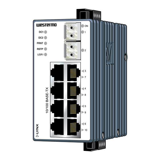
3.3. Hardware Overview Description Description LED indicators SFP transceivers Power connection I/O connection Ethernet connection TX Figure 3. Location of interface ports and LED indicators Lynx L110-F2G & L210-F2G... -
Page 13: Connector Information
Description Description I/O connection Console port Accessorie cable, art. no. 1211-2027 Figure 4. Location of interface ports, bottom view 3.4. Connector Information 3.4.1. Ethernet Connection TX Illustration Pin no. Signal Direction Description In/Out Transmitted/Received data In/Out Transmitted/Received data In/Out Transmitted/Received data Not connected Not connected In/Out... -
Page 14: Power Input
3.4.2. Power Input Illustration Position Product Direction Description marking +DC1 Input Supply voltage +DC2 Input Supply voltage -COM Input Common -COM Input Common Table 7. Power input Lynx supports redundant power connection. The positive inputs are +DC1 and +DC2, the negative input for both supplies are -COM. -
Page 15: Connection To The Console Port
3.4.4. Connection to the Console Port The console port can be used to connect to the CLI (Command Line Interface). 1. Connect the serial diagnostic cable to the console port (use only Westermo cable 1211-2027). 2. Connect cable to your computer (USB port, if drivers are needed they can be downloaded from the Westermo web). -
Page 16: Led Indicators
Table 10. LED indicators 3.6. SFP Transceivers The product supports UL and IEC certified transceivers only. See Westermo's modular transceivers datasheets 100 Mbit and 1 Gbit for supported SFP transceivers, which can be downloaded from the product support pages at www.westermo.com/support/product-... -
Page 17: Supported Transceivers
3.7. Supported Transceivers Firmware prior to 4.4.0 accepts Westermo branded transceivers only. From 4.5.0 other transceivers are accepted with a notice and the product will no longer be UL approved. -
Page 18: Dimensions
3.9. Dimensions Dimensions are stated in mm and are regardless of Lynx model. 96 ±1 52 ±1 92 ±1 Figure 6. Dimensional drawing Lynx L110-F2G & L210-F2G... -
Page 19: Installation
4. Installation 4.1. Mounting This product should be mounted on a 35 mm DIN-rail, which is horizontally mounted inside an apparatus cabinet or similar. It is recommended that the DIN-rail is connected to ground. Snap on the product to the DIN-rail according to the figure. Figure 7. -
Page 20: Cooling
This product runs the Westermo Operating System (WeOS) which provides several management tools that can be used for configuration of the unit. • WeConfig tool This is a custom Westermo tool used for discovery of attached Westermo product. • Web Configuration of the product using the web browser. -
Page 21: Configuration Via A Web Browser
Username: admin Password: westermo Once logged in, use the extensive integrated help function describing all configuration options. Two common task when configuring a new switch is to assign appropriate IP settings, and to change the password of the admin account. - Page 22 • Acknowledge that you wish to conduct the factory reset by unplugging the Ethernet cables. The ON LED will stop flashing. This initiates the factory reset process, and after approximately 1 minute the product will restart with factory default settings. When the product has booted up, the ON LED will show a green light, and is now ready to use.
-
Page 23: Specifications
5. Specifications 5.1. Interface Specifications DC, Power port Lx10-F2G: Lx10-F2G-12VDC: Rated voltage 24 - 48 VDC 12 - 48 VDC Operating voltage 19 - 60 VDC 9.8 - 60 VDC Rated current 240 mA at 24 VDC 420 mA at 12 VDC 120 mA at 48 VDC 220 mA at 24 VDC 115 mA at 48 V... - Page 24 Ethernet TX Electrical specification IEEE std 802.3 Data rate 10 Mbit/s, 100 Mbit/s, manual or auto Duplex Full or half, manual or auto Circuit type TNV-1 Transmission range Up to 150 m with CAT5e cable or better Isolation All other ports Connector RJ-45, auto MDI/MDI-X Cabling...
- Page 25 Logic zero: <1 VDC Console port Electrical specification TTL-level Data rate 115.2 kbit/s Circuit type SELV Data format 8 data bits, no parity, 1 stop bit, no flow control Connection 2.5 mm jack, use only Westermo cable 1211-2027 Lynx L110-F2G & L210-F2G...
-
Page 26: Type Tests And Environmental Conditions
5.2. Type Tests and Environmental Conditions Environmental Basic standard Description Test levels phenomena EN 61000-4-2 Enclosure Contact: ±6 kV Air: ±8 kV Fast transients EN 61000-4-4 Power port ± 2 kV Signal ports Earth port ± 1 kV L-E: ± 0.5 kV, 12 Ω, 9 µF Surge EN 61000-4-5 Power port... - Page 27 Environmental Basic Description Test levels phenomena standard Temperatures EN 60068-2-1 Operational Lx10-F2G-12VDC: -40 to +74°C (-40 to EN 60068-2-2 +165°F) Lx10-F2G: -40 to +70°C (-40 to +158°F) Storage and -50 to +85°C (-58 to +185°F) transport Humidity EN 60068-2-30 Operational 5-95% relative humidity Storage and transport...
-
Page 28: Revision Notes
Change description Rev. O 2020-10 Westermo logo updated, illustrations updated from brown to blue, new information structure throughout the manual, 1.2 About This Guide - new chapter, 2 Safety and Regulations - entire chapter updated, 2.5.3 AREMA - new chapter, 3.1. Product Description updated, 3.2. Available Models - new chapter, 3.5 LED Indicators updated, 3.6 SFP Transceivers updated,... - Page 29 Lynx L110-F2G & L210-F2G...
- Page 30 Lynx L110-F2G & L210-F2G...
- Page 31 Lynx L110-F2G & L210-F2G...
- Page 32 Westermo • SE-635 35 Stora Sundby, Sweden Tel +46 16 42 80 00 Fax +46 16 42 80 01 E-mail: info@westermo.com www.westermo.com 6643-2213 REV. O 2020 10 Westermo Network Technologies AB, Sweden...
Need help?
Do you have a question about the Lynx Series and is the answer not in the manual?
Questions and answers