Carrier 35E Installation And Start-Up Instructions Manual
Single-duct terminal units; variable volume system
Hide thumbs
Also See for 35E:
- Installation and start-up instructions manual (24 pages) ,
- Installation and start-up instructions manual (24 pages) ,
- Installation and start-up instructions manual (28 pages)
Table of Contents
Advertisement
Quick Links
Installation and Start-Up Instructions
CONTENTS
SAFETY CONSIDERATIONS . . . . . . . . . . . . . . . . . . 1
PRE-INSTALLATION . . . . . . . . . . . . . . . . . . . . . . . . 2
General . . . . . . . . . . . . . . . . . . . . . . . . . . . . . . . . . . . 2
Warranty . . . . . . . . . . . . . . . . . . . . . . . . . . . . . . . . . . 2
CONTROL ARRANGEMENTS . . . . . . . . . . . . . . . . . 3
INSTALLATION. . . . . . . . . . . . . . . . . . . . . . . . . . . . . 4
Step 1 - Install Volume Control Box . . . . . . . . . . . 4
Step 2 - Make Duct Connections . . . . . . . . . . . . . 4
Wiring Connections - Electronic Analog
or DDC (Direct Digital Controls) . . . . . . . . . . . . . 6
CONTROL SET-UP . . . . . . . . . . . . . . . . . . . . . . . . . . 9
General . . . . . . . . . . . . . . . . . . . . . . . . . . . . . . . . . . . 9
Set Points . . . . . . . . . . . . . . . . . . . . . . . . . . . . . . . . . 9
Maximum Airflow Set Points . . . . . . . . . . . . . . . . 9
Flow Probe . . . . . . . . . . . . . . . . . . . . . . . . . . . . . . 9
PNEUMATIC CONTROLS. . . . . . . . . . . . . . . . . . . . 11
Sequences 1102 and 1103) . . . . . . . . . . . . . . . . 11
(Control Sequences 1102 and 1103) . . . . . . . . . 12
(Control Sequences 1104-1110) . . . . . . . . . . . . 12
Preventative Maintenance . . . . . . . . . . . . . . . . . . . 13
Pneumatic Control Troubleshooting . . . . . . . . . . 13
ANALOG CONTROLS . . . . . . . . . . . . . . . . . . . . . . 14
(Control Sequences 2100-2105) . . . . . . . . . . . . 14
Thermostat Installation . . . . . . . . . . . . . . . . . . . . . 14
Programming Thermostat . . . . . . . . . . . . . . . . . . . 14
Manufacturer reserves the right to discontinue, or change at any time, specifications or designs without notice and without incurring obligations.
Catalog No. 04-53350004-01
Printed in U.S.A.
Form 35E-4SI
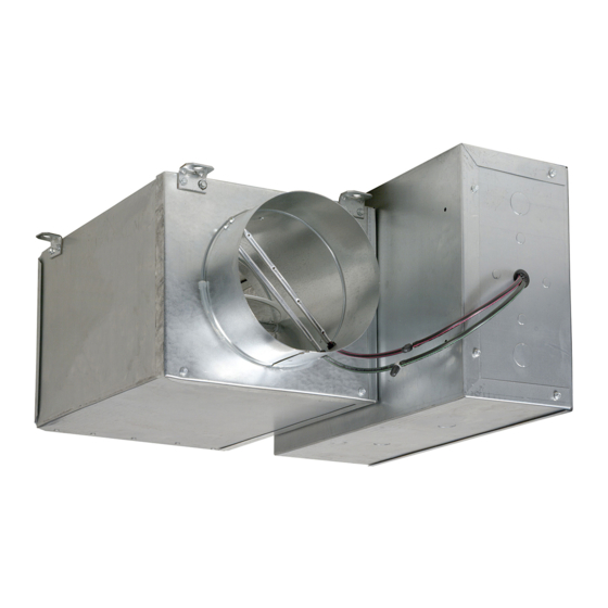
35E Single-Duct Terminal Units
Variable Volume System
Analog Control Troubleshooting . . . . . . . . . . . . .15
START-UP, OPERATION, AND SERVICE. . . . . .17
Start-Up . . . . . . . . . . . . . . . . . . . . . . . . . . . . . . . . . .17
Troubleshooting Proportional SSR Heat . . . . . . .24
SAFETY CONSIDERATIONS
SAFETY NOTE
Air-handling equipment will provide safe and reliable ser-
vice when operated within design specifications. The
equipment should be operated and serviced only by autho-
rized personnel who have a thorough knowledge of system
operation, safety devices and emergency procedures.
Good judgment should be used in applying any manufac-
turer's instructions to avoid injury to personnel or dam-
age to equipment and property.
WARNING
Disconnect all power to the unit before performing
maintenance or service. Unit may automatically start if
power is not disconnected. Electrical shock and personal
injury could result.
CAUTION
If it is necessary to remove and dispose of mercury con-
tactors in electric heat section, follow all local, state, and
federal laws regarding disposal of equipment containing
hazardous materials.
See Fig. 1 for the Proposition 65 Warning Label.
WARNING: Cancer - www.P65Warnings.ca.gov
!
Fig. 1 - Proposition 65 Warning Label
Pg 1
8-18
Replaces: 35E-3SI
Advertisement
Table of Contents
Troubleshooting

Related Manuals for Carrier 35E


Summary of Contents for Carrier 35E
-
Page 1: Table Of Contents
35E Single-Duct Terminal Units Variable Volume System Installation and Start-Up Instructions CONTENTS Analog Control Troubleshooting ... . .15 PROPORTIONAL (SSR) ELECTRIC HEAT SAFETY CONSIDERATIONS ....1 START-UP, OPERATION, AND SERVICE. -
Page 2: Pre-Installation
General claims should be filed with shipper at time of delivery. Store in The 35E unit is a single duct, variable volume terminal avail- a clean, dry, and covered location. Do not stack cartons. When able with factory-installed pneumatic, analog electronic, Car-... -
Page 3: Control Arrangements
Analog Electronic Control Arrangement Pressure-independent control packages are available without The 35E single-duct unit is offered with a wide variety of fac- supplemental heat, with on/off hot water or electric heat, tory-mounted controls that regulate the volume of air delivery... -
Page 4: Installation
Note that reheat coil is in the heavy end of unit. NO CONTROL Step 2 — Make Duct Connections D001: 35E box with control box and 24-v transformer. Also Install supply ductwork on unit inlet collar. Check that used for control enclosure and electric heat. - Page 5 Table 2 — 35E Basic Pressure Data MINIMUM INLET STATIC PRESSURE MINIMUM AIRFLOW (cfm) INLET (Unit and Heat Pressure Drop) ELECTRIC HEAT* SIZE (in.) MAXIMUM MAX kW vs. CFM Velocity Basic Basic + 1- Basic + 2- Basic + 3-...
-
Page 6: Step 3 - Install Sensors And Make Field
LEGEND AFS — Airflow Switch DDC — Direct Digital Controls NOTE: Drawing is typical of 480V, 3-phase, 4-wire heater and control. Refer to actual unit wiring diagram. Fig. 6 — Typical Power Connections for 35E Units with 3-Stage Electric Heat... - Page 7 Table 3 — 35E Heater Power Wiring and Fuse Sizing (Single Phase, 60 Hz) 120 V 208 V 240 V 277 V HEATER BTUH HEATER HEATER HEATER HEATER SIZE (KW) AWG* AWG* AWG* AWG* 1,707 3,413 6,826 16.7 10,239 25.0 14.4...
- Page 8 Fig. 7 — Inlet Flow Sensor, CFM vs Pressure Signal (Linear Averaging Probe Chart)
-
Page 9: Control Setup
4005. This ratio is the same for all sizes regardless of which Each 35E unit is equipped with a flow probe that measures a probe is used. differential pressure proportional to the airflow. The relation-... - Page 10 AIR TERMINAL PERFORMANCE SHEET JOB NAME ______________________________________________ JOB LOCATION __________________________________________ CUSTOMER _____________________________________________ ENGINEER ______________________________________________ BUILDING LOCATION/FLOOR ______________________________ BUS NUMBER ___________________________________________ CONTROL SET POINTS COOLING HEATING CALIBRATION ZONE HEAT OCCUPIED UNOCCUPIED REHEAT (CFM) (CFM) GAIN ADDRESS SIZE NUMBER (IN./CFM) TYPE MULT. Fig.
-
Page 11: Pneumatic Controls
PNEUMATIC CONTROLS Preparation for Balancing (Control Sequences 1102 and 1103) Inspect all pneumatic connections to assure tight fit and proper location. Verify that the thermostat being used is compatible with the control sequence provided (direct acting or reverse CS C- 20 03 0-1 ”... -
Page 12: Balancing Procedure (Control Sequences 1102 And 1103)
Balancing Procedure (Control Sequences 1102 Balancing Procedure (Control Sequences and 1103) 1104-1110) Damper action is factory set at N.O. (normally open), or DIRECT ACTING THERMOSTAT, NORMALLY OPEN N.C. (normally closed). To change, perform the follow- DAMPER (CONTROL SEQUENCE 1102) ing steps: Refer to Fig. -
Page 13: Preventative Maintenance
NOTE: After the “LO STAT P” and “HI STAT P” initial ad- DA HEATING* DA COOLING justments are made, cycle the thermostat pressure a few times to Reset Reset settle the internal reset mechanisms and verify settings. Fine tune Span Span LO STAT ΔP LO STAT ΔP... -
Page 14: Analog Controls
Route the wires through the opening in the back plate. ANALOG CONTROLS Install the back plate directly to the junction box using Balancing Procedures (Control Sequences the screws supplied with the thermostat. Verify the hex 2100-2105) screws used for securing the cover are located at the bot- The analog electronic control system is a pressure indepen- tom before installing. -
Page 15: Analog Control Troubleshooting
NO PRESSURE OUTPUT SIGNAL FROM Analog Control Troubleshooting INLET SENSOR The following troubleshooting procedure is directed towards single duct cooling applications. The same concepts can be Check the wiring. applied to other configurations. Check air flow and sensor. Tubing should be free of NOTE: For about 15 seconds after power is applied, no rotation kinks and restrictions. - Page 16 Table 8 — Thermostat Settings for the CFM per Inlet Size AO1 & SENSOR CFM PER INLET SIZE SIGNAL SETTING (IN. WG) 0.00 0.03 1107 0.05 1565 0.08 1004 1917 0.10 1159 2214 0.13 1296 2475 0.15 1087 1420 2711 0.18 1174 1533...
-
Page 17: Proportional (Ssr) Electric Heat Start-Up, Operation And Service
EHM. The EHM will not allow temperatures over the set- PROPORTIONAL (SSR) ELECTRIC HEAT point so as to prevent overheating, stratification, and energy START-UP, OPERATION AND SERVICE waste from heated air lost through overhead returns. Proportional SSR Heat is an electronic, time-proportional electric heat system. -
Page 18: Wiring
WIRING There are three terminations for 24vac control (Fig. 15, item 5) of the electric heat (applications LX1, LX2, LX5, LX6, See Fig. 15. The EHM control board is powered by 24vac and LX7). “Inc” is for the increase signal in applications LX5 (Fig. - Page 19 YELLOW #18 OPTIONAL CONTROLS DISCHARGE BLUE #18 POWER TEMP 2 STAGE SENSOR HEATER WHITE #18 APPLICATION 2ND STAGE BLACK #18 COMMON RED #18 1ST STAGE 49°C 120°F Tcal 32°C 90°F 20°C EVO/EHM- 68°F 0-10V 2-10V 24Vac Neutral Relay Float 2Stg Xfmr Incr SSRs...
- Page 20 YELLOW #18 24VAC INPUT BLUE #18 2-10 Vdc (4-20mA) BLACK #18 ANALOG OUT POS HEATER RED #18 ANALOG OUT NEG APPLICATION OPTIONAL DISCHARGE TEMP 49°C SENSOR 120°F Tcal 32°C 90°F 20°C EVO/EHM- 68°F 0-10V 2-10V 24Vac Neutral Relay Float 2Stg Xfmr Incr SSRs...
- Page 21 YELLOW #18 OPTIONAL CONTROLS DISCHARGE BLUE #18 BINARY 3 STAGE POWER TEMP SENSOR (Bin) HEATER WHITE #18 2ND STAGE APPLICATION BLACK #18 COMMON RED #18 1ST STAGE 49°C 120°F Tcal 32°C 90°F 20°C EVO/EHM- 68°F 0-10V 2-10V 24Vac Neutral Relay Float 2Stg Xfmr...
- Page 22 Fig. 23 — Sample Proportional SSR Heat Schematic...
-
Page 23: Discharge Termperature Setpoint
DISCHARGE TEMPERATURE SETPOINT not polar sensitive and the two wires may be switched with no effect. Proportional SSR Heat comes with a discharge temperature The desired discharge temperature is set by rotating the dis- setpoint (DTS) option. This option allows a maximum tem- charge temperature set point dial arrow to the maximum out- perature to be set at the board to prevent overheating of dis- let temperature desired. -
Page 24: Troubleshooting Proportional Ssr Heat
“+3” VDC terminal of the relay. output from 0 to 100% over a 4-minute 15-second span. © Carrier Corporation 2018 Manufacturer reserves the right to discontinue, or change at any time, specifications or designs without notice and without incurring obligations.
Need help?
Do you have a question about the 35E and is the answer not in the manual?
Questions and answers