Table of Contents
Advertisement
Advertisement
Table of Contents

Related Manuals for Omron AnyFeeder Series


Summary of Contents for Omron AnyFeeder Series
- Page 1 AnyFeeder AnyFeeder SXM100/140 AnyFeeder SX240/340 Integration Guide R262I-E-01...
- Page 2 The information contained herein is the property of Omron Adept Technologies, Inc., and shall not be reproduced in whole or in part without prior written approval of Omron Adept Technologies, Inc. The information herein is subject to change without notice and should not be construed as a commitment by Omron Adept Technologies, Inc.
-
Page 3: Table Of Contents
Table of Contents Chapter 1: Introduction 1.1 Intended Audience 1.2 Prerequisites AnyFeeder Components 1.3 How Can I Get Help? Websites Related Manuals Support Chapter 2: Safety 2.1 Warnings, Cautions, and Precautions 2.2 Safety Precautions 2.3 What to Do in an Emergency Situation 2.4 Additional Safety Information Robot Safety Guide Chapter 3: Component Setup... - Page 4 Table of Contents Connecting the Servo Power Cable Installing the Pneumatic Line Chapter 5: Configuration with ACE Software 5.1 ACE Software 5.2 ACE Sight Overview Initial Configuration 5.3 Pick and Place Sequence Wizard Safe and Picture-taking Positions Create Feeder Teach Pick for Arm- or Fixed-Mount Camera Teach Place Position Chapter 6: Fine-Tuning 6.1 Configuration Refinement...
-
Page 5: Chapter 1: Introduction
Models, you will also have to teach a new height from the surface for picking. 1.1 Intended Audience This guide is intended for an end-user or integrator who is familiar with Omron Adept robots and the AnyFeeder. It is assumed that you have already selected the robot and AnyFeeder mod- els that you are going to use, as well as the accessories that will be used with those devices, such as the type of backlight, if any, for the AnyFeeder. -
Page 6: Anyfeeder Components
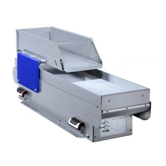
Chapter 1: Introduction AnyFeeder Components Bulk container Purge flap Retainer Feed platform Feed platform front panel Backlight Mounting rail (under feed platform) Handles Pneumatic SX240 and Interface panel SX340 only connector Figure 1-1. AnyFeeder Parts, Model SX240 shown There are four different AnyFeeder-models supported: AnyFeeder SXM100 AnyFeeder SXM140 AnyFeeder SX240... -
Page 7: How Can I Get Help
This can be red or infra-red. 1.3 How Can I Get Help? Websites Refer to one of the following corporate websites: http://www.ia.omron.com http://www.adept.com Related Manuals The following table lists manuals related to this document. To ensure system safety, make sure to always read and heed the information provided in all Safety Precautions, Precautions for Safe Use, and Precaution for Correct Use of manuals for each device which is used in the system. -
Page 8: Support
Chapter 1: Introduction Support If, after reading this manual, you are having problems with your AnyFeeder, contact your local Omron Support. AnyFeeder Integration Guide - Page 8... -
Page 9: Chapter 2: Safety
Chapter 2: Safety 2.1 Warnings, Cautions, and Precautions There are six levels of special alert notation used in our manuals. In descending order of importance, they are: DANGER: This indicates an imminently hazardous electrical situation which, if not avoided, will result in death or serious injury. DANGER: This indicates an imminently hazardous situation which, if not avoided, will result in death or serious injury. -
Page 10: Safety Precautions
All personnel who install, operate, program, or maintain the system must read this guide, the AnyFeeder User’s Guide, the robot user’s guide, and the Robot Safety Guide, and complete an appropriate Omron training course for their responsibilities in regard to the feeder. -
Page 11: Chapter 3: Component Setup
Chapter 3: Component Setup 3.1 Robot System with AnyFeeder This chapter describes the basic parts of a robot system with an AnyFeeder. The following diagram shows a simple overview of typical components. SmartController EX Front Panel All to SmartController EX, if available, or to Robot Interface Panel otherwise Robot, eCobra 600 shown... -
Page 12: Basic Components
The supported models are SXM100, SXM140, SX240, and SX340. Camera If you are using an IR backlight, we recommend you also use an IR lens filter. For Basler cameras sold by Omron Adept Technologies, Inc., the filter is PN: 09324-000. Conveyor or other target 3.3 Power Required Robot - according to robot user’s guide... -
Page 13: Data And Air Required
Chapter 3: Component Setup 3.4 Data and Air Required SmartVision MX to SmartController EX if present, otherwise to eAIB or eMB-40/60R AnyFeeder to SmartVision MX (RS-232) Camera to SmartVision MX T20 Pendant (option) to SmartController EX if present, or else eAIB or eMB-40/60R Front Panel to SmartController EX if present, or else eAIB or eMB-40/60R Pneumatic, to the SX240 and SX340 model AnyFeeders. - Page 14 Chapter 3: Component Setup AnyFeeder SX240 Chipsize Resolution Distance Lens Lens IR Filter inches mm/Pixel Matrix Lens mm 1/1.8 250x337 0.201 09322- 09324- 8 mm 1/1.8 250x337 0.201 1200 09323- 09324- 8 mm 1/1.8 250x337 0.201 1680 09323- 09324- 8 mm 330x330 0.161 Custom...
-
Page 15: Anyfeederinterface Panel Leds
Chapter 3: Component Setup 3.6 AnyFeederInterface Panel LEDs Status LEDs Electrical for Digital I/O Connectors Status LED for High Power Figure 3-2. Interface Panel on AnyFeeder AnyFeeder Integration Guide - Page 15... -
Page 17: Chapter 4: System Installation
Chapter 4: System Installation 4.1 System Cables, without SmartController The letters in the following figure correspond to the letters in the table of cables and parts. The numbers correspond to the steps in the cable installation overview table. The tables are on the pages following the figure. -
Page 18: List Of Cables And Parts
Chapter 4: System Installation The pendant is an option, and may not be present in your system. This figure includes the optional T20 pendant. List of Cables and Parts Open the Accessory box and locate the eAIB XSYSTEM cable. Connect the cables and peri- pherals as shown in the preceding figure. -
Page 19: Cable Installation Overview
Chapter 4: System Installation WARNING: Under no circumstances should you run a robot system, in pro- duction mode, with all three jumpers installed. This would leave the system with no E-Stops. Cable Installation Overview Power requirements for the SmartVision MX industrial PC are covered in that user guide. For 24 VDC, both the robot and a SmartVision MX can usually be powered by the same power supply. -
Page 20: Optional Cables
Chapter 4: System Installation Optional Cables NOTE: The following cables are not covered in the steps in the preceding table. Part Description Notes XIO Breakout Cable, 12 inputs/ Available as option 8 outputs, 5 M eAIB XBELT IO Adapter Cable Available as option The optional eAIB XBELT IO Adapter cable splits the eAIB XBELTIO port into a belt encoder lead, an Intelligent Force Sensor or IO Blox lead, and an RS-232 lead. -
Page 21: System Cables, With Smartcontroller
Chapter 4: System Installation 4.2 System Cables, with SmartController When the optional SmartController EX is included in the system, the Pendant, Front Panel, and XUSR connections must connect to the SmartController EX. XUSR for: - User E-Stop/Safety Gate - Muted Safety Gate The Jumper Plug is required if IEEE 1394 neither of these is used... -
Page 22: List Of Cables And Parts
Chapter 4: System Installation 1. Mount the SmartController and Front Panel. 2. Connect the Front Panel to the SmartController. 3. Connect the pendant (if purchased) to the SmartController. Connect a jumper plug, if no pendant is being used. 4. Connect user-supplied 24 VDC power to the controller. Refer to the SmartController EX User’s Guide. -
Page 23: Cable Installation Overview
Chapter 4: System Installation Part # Part of: Part Cable and Parts List Notes DC Servo Cable to AnyFeeder AnyFeeder AnyFeeder 24 VDC, 10 A power user-supplied supply IEEE 1394 cable standard 8 mm OD Air Line user-supplied a: Only one 04536-000 power supply comes with the 90565-010 kit. The XUSR, XMCP, and XFP jumpers intentionally bypass safety connections so you can test the system functionality during setup. -
Page 24: Optional Cables
Chapter 4: System Installation Step Connection Part Connect camera and cable to SmartVision MX. Use USB PoE 1 on MX. Connect 24 VDC Servo cable to DC Input on AnyFeeder interface panel. U, V Connect an 8 mm OD air line to the pneumatic connector SX240, SX340. Connnect IEEE 1394 cable between SmartController EX and eAIB SmartServo. -
Page 25: Installing Cables And Power
The motor power 24 VDC input is protected with a 10 Amp fuse, and the parallel I/O 24 VDC lines are protected with a 3 Amp fuse. These fuses can be replaced in the field. If you suspect a problem with one or both of these fuses, contact your local Omron Support. AnyFeeder Integration Guide - Page 25... -
Page 26: Rs-232 Cable Installation
Chapter 4: System Installation RS-232 Cable Installation An RS-232 cable is supplied with the AnyFeeder (see following figure). Connects to serial Connects to serial port on port on AnyFeeder SmartVision MX Figure 4-4. Serial Connections Cable Connect the male end of the cable to the RS-232 (J2) port on the AnyFeeder (see following fig- ure). - Page 27 Chapter 4: System Installation Figure 4-6. Servo Power Cable 2. Connect the wire end of the cable to the user-supplied 24 VDC / 10 A regulated power supply. 3. Attach the connector end of the cable to the Motor Power 24 VDC In (J1) connector on the front of the AnyFeeder (see following figure).
-
Page 28: Installing The Pneumatic Line
Chapter 4: System Installation Installing the Pneumatic Line This section describes the pneumatic installation procedure for the AnyFeeder SX240 and SX340. The AnyFeeder SXM100 and SXM140 do not take a pneumatic line. 1. Locate the pneumatic connector below the side handle on the AnyFeeder. Figure 4-8. -
Page 29: Chapter 5: Configuration With Ace Software
Chapter 5: Configuration with ACE Software NOTE: Instructions for using serial communication with an AnyFeeder are covered in the User’s Guide. 5.1 ACE Software The following software is pre-loaded on the SmartVision MX hard drive: Windows® 7 Embedded ACE 3.7.3.150 or later is required to support all of the AnyFeeders listed in this guide ACE Sight 3 (ACE-based vision software) Drivers for Basler ACE cameras The SmartVision MX is designed to run ACE software. -
Page 30: Pick And Place Sequence Wizard
Chapter 5: Configuration with ACE Software Teach a picture-taking position, which is where the robot will move so that it doesn’t block the camera’s view of the pick surface. Teach the camera field-of-view to the robot. Teach the robot where to place a part that it has picked. Figure 5-1. -
Page 31: Safe And Picture-Taking Positions
Chapter 5: Configuration with ACE Software This includes camera setup, calibration, and Locator Model creation. Phase 4/4 - Teach Place for Static Position Configuration Figure 5-2. ACE Sight Pick and Place Sample Safe and Picture-taking Positions For teaching the Safe Position or Picture Position, you can either move the robot using a pendant, the jog pendant feature in ACE, or move the robot manually. -
Page 32: Teach Pick For Arm- Or Fixed-Mount Camera
You may also need to edit the Acquisition Settings to get the best image. Using the Calibration Grid A pdf of the dot grid, used for camera calibration, is located in your Omron folder under Pro- gram Files. Use the file DotPitch10_CalibrationTarget.pdf in the ACE folder. - Page 33 Chapter 5: Configuration with ACE Software Figure 5-3. Grid Calibration Screen Shot AnyFeeder Integration Guide - Page 33...
- Page 34 Chapter 5: Configuration with ACE Software Locator Model In creating your Locator Model(s), ensure that you leave room for the part and tool flange/- gripper to clear the walls of the AnyFeeder. The gripper shape, placement of the pick point on the part, and the region of interest can all affect this.
- Page 35 Chapter 5: Configuration with ACE Software Create Region of Interest The Locator Model creation is followed by creating a region of interest, where the software will look for instances of the Model. The green box shown in the following picture can be adjusted. This step is critical, since the robot should be able to pick any part inside this region.
-
Page 36: Teach Place Position
Chapter 5: Configuration with ACE Software typically the position error will be less than 1 mm. The valid scale factor range is from 0.92 to 1.08 mm. Figure 5-6. Summary of Automatic Calibration Teach Vision Histogram Tool The next step is to set up the histogram tool for the application. You can divide the vision win- dow into three boxes corresponding to three zones: Dispense Zone, Flip Zone, and Front Zone. -
Page 37: Chapter 6: Fine-Tuning
Chapter 6: Fine-Tuning 6.1 Configuration Refinement At this point, the system will be able to recognize the Locator Model taught during the wizard and perform automated pick and place. Most applications can be improved by adjusting para- meters that aren’t covered in the sample application wizard. This could include advanced properties of the vision tools, differentiating between multiple part types, sorting to multiple place locations, avoiding picking overlapping parts, or detecting part defects. - Page 38 Chapter 6: Fine-Tuning Figure 6-1. Dual Locator Models In the Workspace Explorer – e-Series Controller 60 – V+ User Modules – a.feed folder, you can pull up the V+ program related to AnyFeeder motion sequence. The fd.main() under the a.feed folder is the program that tied the ACE Sight histogram Tool to the AnyFeeder motion sequence.
- Page 39 Chapter 6: Fine-Tuning CALL fd.execute(fd.ms.frontmove) VALUE flip.den > fd.flip.thres: ; Flip the product in the pick zone CALL fd.execute(fd.ms.pickflip) VALUE dispense.den < fd.disp.thres: ; Dispense more product into the feeder CALL fd.execute(fd.ms.dispense) VALUE flip.den < fd.flip.thres: ; Move the product from dispense zone to the pick zone CALL fd.execute(fd.ms.pickmove) RETURN .END...
- Page 40 Chapter 6: Fine-Tuning Figure 6-2. Pop-up Window for Variable The motion sequence 1000 – 1003 is configured corresponding to the AnyFeeder movement. In the default setting, the fd.ms.frontmove is tied to motion sequence 1000 and by double-clicking the AnyFeeder module under Workspace Explorer – ACE Sight Pick and Place – Pick - Any- feeder and click the motion sequence button, as shown in the following graphic, the output 1000 is tied to Feed backward [5, 5] + Wait [200].
- Page 41 Chapter 6: Fine-Tuning Figure 6-3. AnyFeeder Motion Sequence Parameters You can get access to all of the Standard Controls that are provided by the AnyFeeder Object window by clicking the Standard Controls button and by adjusting the values for Iterations and Speed.
- Page 42 Chapter 6: Fine-Tuning Figure 6-4. Standard Controls As an example, we will use the dental floss motion sequence 1002. Initially, the motion sequence 1002 is tied to Dispense [5, 5] and Wait [200], but if the AnyFeeder vision window shows most of the parts overlapping each other, or most of the parts presented only in the dis- pense zone, you can try adding flip forward or flip.
- Page 43 Chapter 6: Fine-Tuning Figure 6-5. Front, Flip, and Dispense Zones In Properties, we set ThresholdBlack and ThresholdWhite to 0 and 130, specifying the gray- scale range (0-255) the system will look for. These are explained at the bottom of the window. Typically, you could zoom in on the image and check what gray scale range would cover 90% of the part.
-
Page 44: Other Ace Sight Vision Tools
Chapter 6: Fine-Tuning With a dark background, you will want to adjust the setting for ThresholdBlack and Threshold- White. By triggering the motion sequence 1000 – 1003, you can test how the parts will dispense inside the three zones when different motion sequences are triggered. From the fd.main() program, in the four cases related to triggering motion sequence 1000 –... - Page 45 Chapter 6: Fine-Tuning Figure 6-8. Gripper Clearance Tool Remember to tie the ACE Sight sequence to the Vision Tools of your selection. (Previously we simply tied the ACE Sight sequence to the Locator.) When adding customized vision tools, you must also modify the fd.main() and rob.pick() programs related to VRESULT and VLOCATION.
- Page 46 Chapter 6: Fine-Tuning Figure 6-9. ACE Sight Index ID Used in Sample Code The parameters shown below are V+ vision keywords that will be useful if you want to cus- tomize the system: VRUN: Initiates execution of a vision sequence VLOCATION: Returns the Cartesian transform result of sequence VPARAMETER: Sets the current value of a vision parameter VRESULT: Returns specified result of a vision sequence VSTATE: Returns the state of execution of a vision sequence...
-
Page 47: Chapter 7: Revision History
Date of revision Revision reason and revision page code August. 23, 2017 First edition Manual written by Omron Adept Technologies, Inc Publication reference: 18831-000, Rev A For support please contact your local Omron Support Center: www.ia.omron.com AnyFeeder Integration Guide - Page 47... - Page 48 OMRON ELETRÔNICA DO BRASIL LTDA • HEAD OFFICE São Paulo, SP, Brasil • 55.11.2101.6300 • www.omron.com.br OMRON EUROPE B.V. • Wegalaan 67-69, NL-2132 JD, Hoofddorp, The Netherlands. • +31 (0) 23 568 13 00 • www.industrial.omron.eu Authorized Distributor: Controllers & I/O •...
Need help?
Do you have a question about the AnyFeeder Series and is the answer not in the manual?
Questions and answers