Advertisement
Quick Links
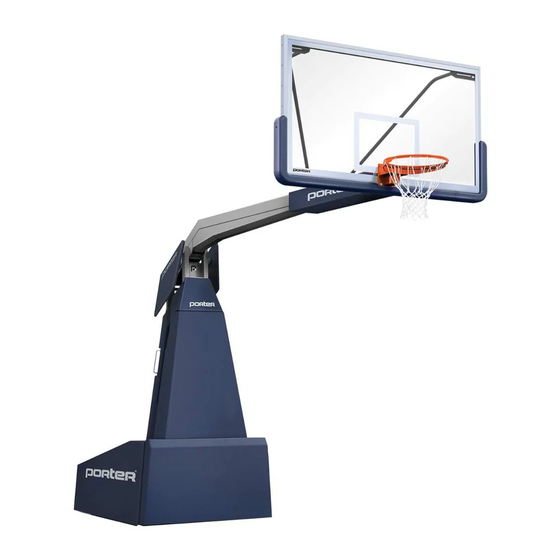
1835 Portable Basketball Backstop
Installation, Operation, and Maitenance Manual
www.porterathletic.com
888-277-7778
INSTALLER NOTE:
UPON COMPLETION OF THE INSTALLATION/ ASSEMBLY OF THIS PORTABLE BACKSTOP,
MAKE SURE THIS INSTRUCTION MANUAL IS IN POSSESSION OF THE OWNER OR
FACILITY MANAGER, TO SAVE FOR FUTURE REFERENCE.
7/23/2018
Copyright 2017 by Porter Athletic.
INST1835
All rights reserved.
Page 1 of 39
Advertisement

Related Manuals for Porter 1835 Series


Summary of Contents for Porter 1835 Series
- Page 1 UPON COMPLETION OF THE INSTALLATION/ ASSEMBLY OF THIS PORTABLE BACKSTOP, MAKE SURE THIS INSTRUCTION MANUAL IS IN POSSESSION OF THE OWNER OR FACILITY MANAGER, TO SAVE FOR FUTURE REFERENCE. 7/23/2018 Copyright 2017 by Porter Athletic. INST1835 All rights reserved. Page 1 of 39...
- Page 2 Center-Strut® design for maximum player and equipment safety, while providing many features for the ultimate in competition play. Your athletes and spectators should enjoy thousands of hours of practice and competition on Porter equipment. This booklet is intended to be used for the initial set-up of your No. 1835 backstop, and as a guide for the safe use and maintenance of the backstop.
- Page 3 Parts List Advisory Information 6 - 16 Assembly and Setup 17 - 19 Operating Procedures 20 - 23 Spring Adjustments Maitenance Guarantee 26 - 39 Appendices 7/23/2018 Copyright 2017 by Porter Athletic. INST1835 All rights reserved. Page 3 of 39...
- Page 4 9/16" Wrench Tape Measure 3/4" Wrench Level 1-5/8" Wrench 5/16" Socket (1/4" Drive) Stepladder 11/16" Drill Bit Portable Drill With Clutch Adjustment 10mm Allen Wrench Phillips-Head Driver 7/23/2018 Copyright 2017 by Porter Athletic. INST1835 All rights reserved. Page 4 of 39...
- Page 5 1835 Portable Basketball Backstop Installation, Operation, and Maitenance Manual Warnings www.porterathletic.com 888-277-7778 7/23/2018 Copyright 2017 by Porter Athletic. INST1835 All rights reserved. Page 5 of 39...
- Page 6 EVEN DEATH . A MINIMUM OF TWO, AND PREFERABLY THREE, INDIVIDUALS (TO HOLD AND MOUNT BACKBOARD) ARE REQUIRED, FOR PROPER AND SAFE ASSEMBLY OF THIS UNIT. 7/23/2018 Copyright 2017 by Porter Athletic. INST1835 All rights reserved. Page 6 of 39...
- Page 7 4. While backboard is in this position, secure in place using two (2) 3/8" flat washers, 3/8" lock washers, and 3/8" hex nuts onto each 3/8" x 1-1/4" carriage bolt. Snug tighten only. DETAIL "B" 7/23/2018 Copyright 2017 by Porter Athletic. INST1835 All rights reserved. Page 7 of 39...
- Page 8 7. Attach back of swaybrace (#3) to the horizontal extension assembly (see Detail “D”) using one (1) u-clamp, two (2) 3/8” lock washers, and two (2) 3/8”-16 unistrut nuts. Finger tighten only. DETAIL "D" 7/23/2018 Copyright 2017 by Porter Athletic. INST1835 All rights reserved. Page 8 of 39...
- Page 9 9. Keeping all individuals clear from beneath the unit (front and back), from the side carefully loosen threaded rods and remove shipping clamps (see Detail “A”) at this time. 7/23/2018 Copyright 2017 by Porter Athletic. INST1835 All rights reserved. Page 9 of 39...
- Page 10 After a few turns of each nut, check that the goal is at the 10ft playing height and continue adjustment as necessary. 7/23/2018 Copyright 2017 by Porter Athletic. INST1835 All rights reserved.
- Page 11 10ft from the court floor. Installing locator pins (#6) (see page #14) will ensure the backboard and goal are always in the same position on the court floor. DETAIL "H" 1/8" to 3/8" 7/23/2018 Copyright 2017 by Porter Athletic. INST1835 All rights reserved. Page 11 of 39...
- Page 12 This should be done with the unit in the upright, playing position as part of setting the goal height. 7/23/2018 Copyright 2017 by Porter Athletic. INST1835 All rights reserved.
- Page 13 DROP A PLUMB LINE FROM THE EXACT CENTER OF THE GOAL AND POSITION UNIT TO ALIGN WITH NAIL HOLE ON FLOOR. SHIFT BASE FROM SIDE TO SIDE AS REQUIRED TO CENTER ON COURT. 7/23/2018 Copyright 2017 by Porter Athletic. INST1835 All rights reserved. Page 13 of 39...
- Page 14 Route the cable as shown in Detail "J" to easily raise and lower the locator pin by pulling the cable. Once the padding is installed, the unit is now ready for competition. 7/23/2018 Copyright 2017 by Porter Athletic. INST1835 All rights reserved.
- Page 15 POINTS THROUGHOUT THE TRAVEL OF THE RAISING/LOWERING CYCLE OF THE BACKSTOP. IF CABLES ARE LEFT ATTACHED TO THE JUNCTION BOX, DURING EACH SETUP CHECK FOR KINKED OR FRAYED CABLES AND REPLACE AS-NEEDED. 7/23/2018 Copyright 2017 by Porter Athletic. INST1835 All rights reserved. Page 15 of 39...
- Page 16 POSITION TO PREVENT THE BACKSTOP FROM SUDDENLY SPRINGING TO THE UP POSITION. THIS COULD RESULT IN SEVERE INJURIES OR EVEN DEATH. CONSULT THE MANUFACTURER WHEN IN DOUBT. 7/23/2018 Copyright 2017 by Porter Athletic. INST1835 All rights reserved. Page 16 of 39...
- Page 17 Note: Docking trays can be removed from floor when not in-use. If docking trays were removed, replace docking trays before moving portables into position before next use. 7/23/2018 Copyright 2017 by Porter Athletic. INST1835 All rights reserved. Page 17 of 39...
- Page 18 2. Plug power extension cord into the power socket of the control box (see Detail “L”). 3. Plug the control pendant into the pendant socket of the control box (see Detail “L”). 7/23/2018 Copyright 2017 by Porter Athletic. INST1835 All rights reserved.
- Page 19 Note: Docking trays can be removed from floor when not in-use. If docking trays were removed, replace docking trays before moving portables into position before next use. 7/23/2018 Copyright 2017 by Porter Athletic. INST1835 All rights reserved. Page 19 of 39...
- Page 20 For proper operation, the backstop must be manually pushed to the full up (playing) position, or the full down (storage) position. Operate backstop slowly to prevent damage or injury. 7/23/2018 Copyright 2017 by Porter Athletic. INST1835 All rights reserved.
- Page 21 8. Remove the hair pin cotter pins and large washers on each end of the rear spring bar. 9. Remove the tension studs from the forward spring bar by first removing the jam nuts (B’s and C’s), lock washers, and washers. 7/23/2018 Copyright 2017 by Porter Athletic. INST1835 All rights reserved. Page 21 of 39...
- Page 22 14. If further adjustment is necessary, follow the procedures on page 21 for either “DIFFICULTY IN RAISING UNIT TO PLAYING POSITION” or “DIFFICULTY IN LOWERING UNIT TO PLAYING POSITION” respectively. 7/23/2018 Copyright 2017 by Porter Athletic. INST1835 All rights reserved.
- Page 23 1835 Portable Basketball Backstop Installation, Operation, and Maitenance Manual Spring Adjustment www.porterathletic.com 888-277-7778 7/23/2018 Copyright 2017 by Porter Athletic. INST1835 All rights reserved. Page 23 of 39...
- Page 24 Check that docking trays and anchors are functioning properly and structurally sound. • If a shot clock is installed, check that all hardware is properly tightened and support structure is structurally sound. 7/23/2018 Copyright 2017 by Porter Athletic. INST1835 All rights reserved. Page 24 of 39...
- Page 25 WARNING: This product can expose you to Urethane, which is known to the State of California to cause cancer and birth defects or other reproductive harm. For more information go to www.p65warnings.ca.gov. 7/23/2018 Copyright 2011 by Porter Athletic. INST1835 All rights reserved. Page 25 of 39...
- Page 26 Installation, Operation, and Maitenance Manual Appendix A - Dimensional Diagrams; 10'8" Model www.porterathletic.com 888-277-7778 DETAIL "C" DETAIL "D" DETAIL "B" DETAIL "F" DETAIL "E" 2 " 8 " 7/23/2018 Copyright 2017 by Porter Athletic. INST1835 All rights reserved. Page 26 of 39...
- Page 27 Installation, Operation, and Maitenance Manual Appendix A - Dimensional Diagrams; 10'8" Model www.porterathletic.com 888-277-7778 DETAIL "C" DETAIL "D" DETAIL "B" DETAIL "F" DETAIL "E" 2 " 150" 7/23/2018 Copyright 2017 by Porter Athletic. INST1835 All rights reserved. Page 27 of 39...
- Page 28 ANCHORS 8 " DOCKING TRAY LOCATOR C L FLOOR ANCHORS 2 " 33" LOCKING PIN COURT FLOOR WOOD THREADED INSERT CONCRETE FLOOR 00247100 FLOOR ANCHOR SHOWN 7/23/2018 Copyright 2017 by Porter Athletic. INST1835 All rights reserved. Page 28 of 39...
- Page 29 1835 Portable Basketball Backstop Installation, Operation, and Maitenance Manual Appendix C - Frame Padding Installation www.porterathletic.com 888-277-7778 Copyright 2017 by Porter Athletic. All rights reserved. Page 29 of 39...
- Page 30 Appendix C - Frame Padding Installation www.porterathletic.com 888-277-7778 Install the front pad using the attached hinge and the 1/4-20 x 3/4" lg bolts and nylock nuts. M1290 HDWE012600E0 Copyright 2017 by Porter Athletic. All rights reserved. Page 30 of 39...
- Page 31 Installation, Operation, and Maitenance Manual Appendix C - Frame Padding Installation www.porterathletic.com 888-277-7778 Screw on the lower mast pad using five (5) #8 x 5/8” lg screws HDWE060320E0 Copyright 2017 by Porter Athletic. All rights reserved. Page 31 of 39...
- Page 32 Installation, Operation, and Maitenance Manual Appendix C - Frame Padding Installation www.porterathletic.com 888-277-7778 Screw on the upper mast pad using two (2) #8 x 5/8” lg screws HDWE060320E0 Copyright 2017 by Porter Athletic. All rights reserved. Page 32 of 39...
- Page 33 RIGHT OPPOSITE HAND 4 " 2 " 8" the unit’s base z-strips correctly. 2 " 2 " Copyright 2017 by Porter Athletic. All rights reserved. BOTTOM OF PAD ASSEMBLY Page 33 of 39...
- Page 34 Installation, Operation, and Maitenance Manual Appendix C - Frame Padding Installation www.porterathletic.com 888-277-7778 Remove the Velcro tape backing from the 2-sided pad and insert it between the side pad and mast pad. Copyright 2017 by Porter Athletic. All rights reserved. Page 34 of 39...
- Page 35 Installation, Operation, and Maitenance Manual Appendix C - Frame Padding Installation www.porterathletic.com 888-277-7778 HDWE060320E0 Screw on the front side panels using two (2) #8 x 5/8” lg screws Copyright 2017 by Porter Athletic. All rights reserved. Page 35 of 39...
- Page 36 Installation, Operation, and Maitenance Manual Appendix C - Frame Padding Installation www.porterathletic.com 888-277-7778 HDWE060320E0 Screw on the back side panels using two (2) #8 x 5/8” lg screws Copyright 2017 by Porter Athletic. All rights reserved. Page 36 of 39...
- Page 37 HDWE060320E0 Bolt the assembly onto the unit using the 3/8-16 x 1-1/2" lg bolts, flat washers, lock washers, and hex nuts hex nut_ai (1) HDWE012020E0 HDWE040020E0 HDWE050040E0 HDWE050040E0 Copyright 2017 by Porter Athletic. All rights reserved. Page 37 of 39...
- Page 38 1835 Portable Basketball Backstop Installation, Operation, and Maitenance Manual Appendix C - Frame Padding Installation www.porterathletic.com 888-277-7778 Place the "DO NOT STAND" spring cover over the springs Copyright 2017 by Porter Athletic. All rights reserved. Page 38 of 39...
- Page 39 1835 Portable Basketball Backstop Installation, Operation, and Maitenance Manual Appendix C - Frame Padding Installation www.porterathletic.com 888-277-7778 OPTIONAL No. 1834CXX BOOM PAD Use the straps to attach the boom pad Copyright 2017 by Porter Athletic. All rights reserved. Page 39 of 39...
Need help?
Do you have a question about the 1835 Series and is the answer not in the manual?
Questions and answers