Table of Contents
Advertisement
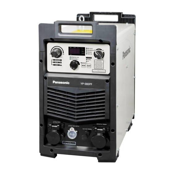
IGBT Controlled Plasma Arc Cutting Power Source
● Thank you for your purchase of Panasonic cutting power source.
● Before operating this product, please read the instructions carefully and save this manual
for future use. First of all, please read "Safety precautions" or "Safety manual".
● SPEC. No.:YP-060PF3HGF, YP-060PF3HJE, YP-100PF3HGF, YP-100PF3HJE
Panasonic Welding Systems (Tangshan) Co., Ltd.
Operating Instructions
Model N o.
YP-060PF
YP-100PF
TSM50245-02
Advertisement
Table of Contents
Troubleshooting

Related Manuals for Panasonic YP-060PF


Summary of Contents for Panasonic YP-060PF
- Page 1 Model N o. YP-100PF ● Thank you for your purchase of Panasonic cutting power source. ● Before operating this product, please read the instructions carefully and save this manual for future use. First of all, please read “Safety precautions” or “Safety manual”.
-
Page 2: Table Of Contents
Table of Contents 1 Safety ···························································· 1 8.8 The setting on the warning in case air pressure is out of the recommended range ······33 2 Important Safety Items ··································· 1 3 Rated Specifications ······································ 3 8.9 The operation locking function ···················34 3.1 Specifications table ·····································... - Page 3 Features ·PF3 series machine is an energy saving, compact and light weighted plasma cutting machine controlled by new type inverter technology. ·The contact and non-contact cutting mode can be selected. The main circuit equipped with pilot arc circuit is able to start the arc instantly with excellent performance. ·Two functions: plasma cutting and plasma gouging.
- Page 4 Disclaimer: ◆ Panasonic Welding Systems(Tangshan) Co., Ltd., (hereinafter called “PWST”) and its affiliates (including any subcontractor, sales company or agent) shall not assume or undertake any responsibility or liability of the followings: •Any problem arising out of, or directly or indirectly attributable to, the failure of user to carry out those normal maintenance, normal adjustment and periodical check of this product.
-
Page 5: Safety
2 Important Safety Items WARNING (10)Perform periodic checks without fail and repair or Cutting power source replace any damaged parts before using the power Observe the following instructions to source. prevent the hazard. Ventilation and protective equipment (1)Never use the cutting power source for other than Oxygen deficit, fume and gas cutting purpose. - Page 6 2 Important Safety Items (continuous) CAUTION performing maintenance work or repair work, provide Installing shielding (curtain etc.) fence or the like around the cutting machine so that unauthorized person can not come close carelessly. Arc flash, flying spatter, slugs, and noise generated during cutting can Cutting wire damage your eyes, skin and hearing.
-
Page 7: Rated Specifications
3 Rated Specifications 3.1 Specifications table Rated input voltage 380V Model number YP-060PF YP-100PF Spec. number YP-060PF3HG YP-100PF3HG Rated input voltage 380V AC (Allowable fluctuation range: ±20%) Rated frequency 50 / 60 No. of phase — Three phase 9.81(Cutting) 17.67(Cutting) 11.32(Gouging) - Page 8 3 Rated Specifications (continuous) Rated input voltage 415V Model number YP-060PF YP-100PF Spec. number YP-060PF3HJ YP-100PF3HJ Rated input voltage 415V AC (Allowable fluctuation range: ±20%) Rated frequency 50 / 60 No. of phase — Three phase 9.76(Cutting) 17.59(Cutting) 11.25(Gouging) 19.71(Gouging) Rated input 7.19(Cutting)
-
Page 9: Standard Accessories
3 Rated Specifications (continuous) 3.2 Standard accessories Name Product number Qty. Remarks Connector KDP16d-K Air hose TSMW6079-□□ 3.3 Dimensions... -
Page 10: Rated Duty Cycle
3 Rated Specifications (continuous) 3.4 Rated duty cycle YP-060PF Duty cycle (%) 100% Output current (A) Duty cycle (%) 100% (77A below) Rated Duty Cycle Output current (A) The rated duty cycle is 60 %. This means that the machine can cut for a total of 6 minutes out of any 10 minutes at the rated current, and then, during the remaining 4 minutes, the machine must be cooled down to prevent overheating. -
Page 11: Thermal Protection
3 Rated Specifications (continuous) 3.5 Thermal protection Cutting power source is equipped with a thermal switch at the radiator fin of IGBT to monitor the temperature. When the abnormal temperature happens, the thermal switch takes action and cut off the output. ... -
Page 12: Installation And Power Supply Facility
4 Installation and Power supply facility CAUTION When installing or transporting the cutting machine, wear long sleeve shirts, leather gloves and safety shoes to prevent injury. 4.1 Installation site (1) Locate indoors only, where the floor is capable of supporting the weight of the product. (2) Avoid exposure to the direct sun light or the rain or water spray. -
Page 13: Installation Transportation
4 Installation and Power supply facility (continuous) 4.2 Installation transportation When hanging this product for transportation, hang it at two eyebolts. ●Do not lift the product on your own. As this product is heavy, it is dangerous to lift it on your own. Involve plural number of persons with its lifting. -
Page 14: Power Supply Equipment
4 Installation and Power supply facility (continuous) 4.3 Power supply equipment Observe the following to prevent burnout, destruction of parts and CAUTION unstable arc. YP-060PF Three phase ,380V AC, Three phase ,415V AC, Input power source 50 / 60 Hz (common) -
Page 15: Configuration
5 Configuration 5.1 Equipment necessary for cutting Part(※)since the spare parts for the user. Power distribution box(※) Ventilation facilities(※) Ventilation(※) Input power cable(※) Gas hose(※) cutting machine Ground wire( (※) Cutting torch(※) Base metal cable(※) Base metal(※) Ground wire(※) Ventilation(※)... -
Page 16: Peripherals
Rated Cooling Rated Cable Apply Spec number Shape current method duty cycle length machine YT-06PD3HAE Angle Air cooling 100% YP-060PF YT-06PE3HAE Air cooling 100% YP-060PF YT-06PD3HAF Angle Air cooling 100% YP-060PF YT-06PE3HAF Air cooling 100% YP-060PF YT-06PD3HAG Angle Air cooling... -
Page 17: Names And Functions
6 Names and Functions 6.1 Major operation part names Input terminal block Power switch Rear Front Input terminal cover Gas regulator rotary knob Earthing terminal Operation area Cable holding board The cooling Gas inlet fan outlet Output terminal area The cooling fan air inlet Front, left side are air outlets Note:... -
Page 18: The Power Switch
6 Names and Functions (continuous) 6. 2 The power switch WARNING Before starting the generator, please cut off power switch. Front Power switch •The power source ON/OFF change-over on the machine outer case. After turning on power switch, LED on the operation area is lit and software version number is displayed, then cooling fan starts to rotate, finally machine runs into stand-by status. -
Page 19: Operation Area
6 Names and Functions (continuous) 6.4 Operation area Reference : 7-segment numeric display and round indicator in this Chapter are named LED in short. Please pay attention to the use of displayed data ·There may be differences between the displayed setting current value on the digital display window ①... - Page 20 6 Names and Functions (continuous) ③ The dial The rotary knob can provide the function of potentiometer (The setting of current and time etc.). For example, in order to set cutting current as 30A, please rotate right (increase) or left (decrease) until displayed value (digital display window) reaches 30A.
-
Page 21: Connection
7 Connection WARNING Observe the following cautions to prevent electrical shocks. Touching an electrically charged section can cause a serious electrical shock or burn. · Before installing or performing maintenance/inspection work, turn off all the input power supplies at the distribution box; and overhaul at least 5 minutes after turning off the switch box. -
Page 22: The Connection Of The Grounding Wire And Input Side Cable
7 Connection (continue) 7.2 The connection of the grounding wire and input side cable. WARNING Observe the following cautions to prevent electrical shocks. Touching an electrically charged section can cause a serious electrical shock or burn. ·Attach a switch with fuse of specified capacity or no-fuse Breaker (or leakage breaker) to the switch box for each equipment. - Page 23 7 Connection (continue) 7.2.2 The connection of input cable •For safety, please connect the input cable of the power source after doing the connection of the output cable. •Attach a switch to the distribution box for each the Product. Power distribution box Input terminal cover Input terminal block Switch...
-
Page 24: The Air Input
7 Connection (continue) 7.3 The air input Please connect as per the sequence as follows: (1) Install accessory pipe nut, coupling and hose pipe clamp on the air hose leading from air supply (air compressor). (2) Use pipe nut to connect air inlet. Note: ·Please use the dry and clean air without oil content. -
Page 25: Settings And Operations
8 Settings and Operations (2) The following product information is displayed 8.1 Power (ON) / (OFF) on the digital display. (2-1) DPS number (Software ID Number) Front Power switch (2-2) Version number Note: · When a generator is used, please be sure to turn off power switch of the Machine before starting up generator. -
Page 26: Setting The Cutting Current
8 Settings and Operations 8.4 Cutting navigation 8.4.1 The condition setting method for (continue) cutting navigation 8.3 Setting the cutting current (1) On the stand-by status, press selection button Set the cutting current as follow. 4 times, cutting navigation LED is lit. (1) On the stand-by mode, the digital display indicates the set cutting current. - Page 27 (5) Select manual / automatic. 8 Settings and Operations ·「Hnd」: Applicable to the manual cutting. (continue) ·「Aut」: Applicable to the automatic SPM cutting. (3) Selection of base metal material. ·When digital display window shows 「―――」, Turn the dial, selecting material, press the press DECIDE button to return to base metal DECIDE button.
- Page 28 8.4.2 The confirmation on the cutting 8 Settings and Operations navigation condition (continue) (6) Cutting condition is displayed circularly in the After the cutting navigation is confirmed, if cutting sequence of 「 cutting current 」 , 「 cutting tip — setting current value is in the status of unchanged, base metal distance」, 「...
-
Page 29: The Submenu
8 Settings and Operations 8.5 The submenu ·The submenu is a mode executing a fine (continue) adjustment or setting on the cutting machine (3) The display circularly shows in the sequence power source according to parameter unit. of material, thickness, manual / automatic ·Please modify set values according to the need. - Page 30 (3) Rotate the dial to modify set values of 8 Settings and Operations parameters and then press the DECIDE button. (continue) After that of parameter number of the initial selection can be displayed. 8.5.2 The settings in the submenu (1) On the cutting stand-by status, press selection button 5 times to switch to submenu.
- Page 31 8 Settings and Operations (continue) 8.5.3 The contents of submenu Setting Setting items Set unit Default Descriptions Gouging OFF(oFF) — Place gouging selection ( P01 ) at " ( on ) " side to enable air plasma gouging. select * 1 ON(on) When placing the cutting torch mornitoring selection ( P02 ) at "...
-
Page 32: The Cutting Torch Monitoring Function
8 Settings and Operations (continue) Setting Setting items Set unit Default Descriptions Select the length of the cable to be used. Cutting torch By using the selection on the cable length and cutting torch , the recommended cable length 10,20,30 gas pressure can be automaticaly changed according to the specifications of select the cutting torch. - Page 33 (2) Enter 【the cutting torch monitoring selection 8 Settings and Operations 「p02」 】 of direct setting or submenu again, turn (continue) the dial and select 「(on) 」, press the DECIDE 8.6.1 Operation method button. (1) Enter 【the cutting torch monitoring selection ·For setting in “direct setting”...
- Page 34 8.6.2 The confirmation method for 8 Settings and Operations monitoring number of times and (continue) duration of the cutting torch (3) When one of number of arc ignition times and ●The confirmation method for setting number of actual cutting time reaches the set value, after times and duration cutting operation finishes, by using 【the cutting Select 【the cutting torch monitoring number of...
- Page 35 8.6.3 The setting modification method 8 Settings and Operations (1) Enter direct setting or submenu 【the cutting (continue) torch monitoring selection (p02) 】. Turn the dial ●The confirmation method of the remaining and set on「(off) 」, press the DECIDE button. number of times and remaining duration ·For direct setting During the status of displaying the setting of 【the...
- Page 36 8.6.4 Precautions for use 8 Settings and Operations ·The detecting grade before shipment status of (continue) the electrode and cutting tip of the cutting torch (2) Enter submenu 【the cutting torch monitoring on monitoring the service life is made according number of times setting 「P04 「】...
-
Page 37: The Gouging Function
8 Settings and Operations 8.8 The setting on the warning in case air pressure is out of the (continue) recommended range 8.7 The gouging function During the cutting, when air pressure exceeds the ·When turn on 「ON」 the function of direct recommended ranges, the Product displays setting or 【... -
Page 38: The Operation Locking Function
(2) Turn the dial to display 【 operation lock 8 Settings and Operations 「loc」 】 press 「DECIDE」 button. (continue) 8.9 The operation locking function The Product can execute the locking of such operations like the set current value and modification of submenu etc. Note: When the operation locking function is enabled, functions as follows:... - Page 39 8.9.3 The reset of operation locking 8 Settings and Operations password (continue) Note: 8.9.2 The modification method of If you want to stop in the half way during the operation lock password resetting of the password, you may just turn off the power source.
- Page 40 8 Settings and Operations (continue) (2) On the status displaying 「999」, you can continue to turn the dial until digital display window shows 【 reset 「rst」 】 . On this status, after pressing 「DECIDE」 button, all unit LEDs blinks for 2S. As a result, operation locking status returns to factory setting status 「123」.
-
Page 41: Operation Methods
9 Operation methods 9.1 Measure for safety To protect you and other people from gases, fumes and DANGER lack of oxygen that may be generated during cutting operation, make sure to prepare ventilation facilities and use protective equipment, etc. ● Cutting operations in narrow spaces may cause asphyxia due to lack of oxygen. ●... -
Page 42: The Confirmation On Air
9 Operation methods (continue) (4) For electrode, cutting tip, please use specialized hand tool in accessory of the cutting torch to fasten them firmly. (5) Please use hand to fasten the protection cover of the cutting torch. Note: · When you use pliers or wrench and use too much strength, the cutting torch may be damaged. ·... -
Page 43: The Cutting Technique And Condition
10 The cutting technique and condition WARNING Plasma arc exposure against a body part such as hand or finger may cause a burn. ·When the cutting torch switch is pressed, air can blow from cutting tip end and high voltage can be generated from the cutting tip, so please never touch it! Regarding cutting method of the Product, according to the relative position of cutting tip and cutting material, cutting methods can be classified into contact cutting and non-contact cutting. -
Page 44: Non-Contact Cutting
10 The cutting technique and condition (continue) 10.2 Non-contact cutting WARNING Do not touch the electrically charged section to prevent electrical shocks and burnt. ·During cutting do not touch cutting tip and electrode of the cutting torch end. ※ Please avoid unnecessary operation of the cutting torch switch, otherwise the consumption of the electrode can be accelerated by generating arc without base metal. -
Page 45: The Piercing
10 The cutting technique and condition (continue) 10.3 The piercing WARNING To avoid burnt, please observe the below mentioned precautions: ·During piercing, spatter may blow out, keep the hands and face away. Before executing piercing, make the cutting start end according to 【10.1 contact cutting 】 or 【10.2 non-contact cutting 】. -
Page 46: The Gouging
For low-carbon steel and stainless steel cutting, the recommended thicknesses for pulse cutting are as follows: Cutting current set Recommended Model number value cutting thickness YP-060PF 60A(maximum) 6mm or less YP-100PF 100A(maximum) 12mm or less Note: ·For pulse cutting, the maximum cutting capacity (maximum cutting thickness and speed) is reduced. -
Page 47: The Cutting Condition
10.6.1 The cutting thickness The below mentioned materials are applicable to plasma cutting The maximum cutting thicknesses of YP-060PF are shown in the table below The maximum cutting thickness of YP-100PF are shown in the table below When carbon steel is cut by different machine, the recommended cutting and piercing thickness range... - Page 48 10 The cutting technique and condition (continue) YP-060PF3 Data for cutting navigation(Cooperate cutting torch YT-06PD3/PE3) Recommended Recommended The maximum Cutting tip - base cutting current cutting speed cutting speed metal distance Thickness (A) (m/min) (m/min) (mm) Material (mm) auto Manual Manual automatic Manual...
- Page 49 10 The cutting technique and condition (continue) YP-060PF3 Data for cutting navigation(Cooperate cutting torch YT-06PD3/PE3) Recommended Recommended Cutting tip - base The maximum cutting cutting current cutting speed metal distance Thickness speed(m/min) (A) (m/min) (mm) Material (mm) autom Manual Manual automatic Manual automatic...
- Page 50 10 The cutting technique and condition (continue) YP-060PF3 Data for cutting navigation(Cooperate cutting torch YT-06PD3/PE3) Recommended Cutting base Recommended The maximum cutting cutting current metal distance cutting speed (m/min) Thickness speed(m/min) (A) (mm) Material (mm) automa Manual Manual automatic Manual automatic Manual automatic...
- Page 51 10 The cutting technique and condition (continue) YP-060PF3 Data for cutting navigation(Cooperate cutting torch YT-06PD3/PE3) Recommended Recommended Cutting tip - base The maximum cutting cutting current cutting speed metal distance Thickness speed(m/min) (A) (m/min) (mm) Material (mm) auto Manual Manual automatic Manual automatic...
- Page 52 10 The cutting technique and condition (continue) YP-100PF3 Data for cutting navigation(Cooperate cutting torch YT-10PD3/PE3) Recommended Recommended The maximum Cutting tip - base cutting current cutting speed cutting speed metal distance Thickness (A) (m/min) (m/min) (mm) Material (mm) auto Manual Manual automatic Manual...
- Page 53 10 The cutting technique and condition (continue) YP-100PF3 Data for cutting navigation(Cooperate cutting torch YT-10PD3/PE3) Recommended Recommended Cutting tip base The maximum cutting cutting current cutting speed metal distance Thickness speed(m/min) (A) (m/min) (mm) Material (mm) automa Manual Manual automatic Manual automatic Manual...
- Page 54 10 The cutting technique and condition (continue) YP-100PF3 Data for cutting navigation(Cooperate cutting torch YT-10PD3/PE3) Recommended Recommended Cutting tip - base The maximum cutting cutting current cutting speed metal distance Thickness speed(m/min) (A) (m/min) (mm) Material (mm) auto Manual Manual automatic Manual automatic...
- Page 55 10 The cutting technique and condition (continue) YP-100PF3 Data for cutting navigation(Cooperate cutting torch YT-10PD3/PE3) Recommended The maximum Cutting tip - base Recommended cutting speed cutting speed metal distance Thickness cutting current(A) (m/min) (m/min) (mm) Material (mm) autom autom Manual Manual Manual automatic...
-
Page 56: The Air Post Flow Sequence Chart
10 The cutting technique and condition (continue) 10.7 The air post flow sequence chart To protect cutting tip and electrode, after cutting finishes air is blown around 20s to cool down the torch. The sequences of air post flow (about 20s) are shown here: During after flow ·General after flow Operation limiting time... -
Page 57: The Treatment After Operation
11 The treatment after operation 11.1 Discharge the condensate water from the cutting torch The condensate water the water transformed from the moisture content in the cutting air. WARNING Please do not operate the cutting torch switch at random. ·air can blow from cutting tip end and high voltage can be generated from the cutting tip of the cutting torch, causing fatal electric shock and burn. -
Page 58: Maintenance
·Check the items indicated in the “Table 1” and “Table 2”, and conduct the cleaning and replacement of parts if necessary. · For replacement of parts, make sure to use our genuine parts for Panasonic air plasma cutting torch to keep its performance and functions 12.1.1 The cutting machine (the Product) - Page 59 12 Maintenance (continue) 12.1.2 Cables Table 2 Position Check point Remarks ·Cable insulation: If cable coating is worn or damaged. Output side ·Cable connection area: If any current-carrying parts are Base metal To secure the physical safety and side exposed (insulation is damaged) or loose connection. Stable arc, check those cables in an Cable If any heavy items not placed on the cable.
-
Page 60: Periodic Inspection
12 Maintenance (continue) 12.2 Periodic inspection WARNING Touching any current-carrying parts may cause a fatal electric shock or burn injury To secure physical safety, make sure that a qualified person or a person who is familiar with the cutting machine takes care of a regular check. ·... - Page 61 12 Maintenance (continue) 12.2.1 Periodic inspection contents While details for checking are shown below table, consider any additional check items according to your conditions of use. If there is a mass of dust and amount of contaminant which can pose great impact on the performance of the Product, please adjust the frequency according to the inspection results.
-
Page 62: Precautions For Insulation Withstand Voltage
For example, when they are used under the rated specifications, the life of the cooling fan is about 40000 hours, and that of the electrolytic capacitor of YP-100PF is about 102100 hours, YP-060PF electrolytic capacitor about 68708 hours. Their actual duration depends on how those items are used by customers. -
Page 63: Troubleshooting
13 Troubleshooting Touching any current-carrying parts may cause a fatal electric shock or burn injury To prevent a fatal accident, such as an electric shock, burn injury, etc., make sure to observe the following: WARNING ●To secure physical safety, only educated and/or skilled persons who well understand the machine should perform Troubleshooting work. - Page 64 13 Troubleshooting (continue) Error abnormal Causes and · countermeasures number content Current detection Failure may happen. abnormity · please contact distributor pressure Air pressure lower than 0.28mpa abnormity ·It’s OK to use when the air pressure is within the recommended range. ·...
-
Page 65: Troubleshooting At The Initial Stage
13 Troubleshooting (continue) 13.2 Troubleshooting at the initial stage ·Sometimes the problems of incapable of cutting, unstable arc and poor cutting results are caused by some other factors instead of the Product. ·The general cutting abnormities are listed on 【13.2.1 Troubleshooting chart at the initial stage for cutting abnormal】. -
Page 66: Circuit Diagram
14 Circuit diagram... - Page 67 14 Circuit diagram (continue)
-
Page 68: Repair Parts List
15 Repair parts list See the recommended repair parts list and have parts in stock if needed 25 24 22 27 26... - Page 69 15 Repair parts list (continue) Mark Description Part number Qty. used Remarks Air regulator rotary RA800-8PB knob Knob TSMH0062-□□ Output terminal TSME0196-□□ (cutting torch side) Cutting torch MT25B2PM switch socket Pilot arc terminal TSM16140-□□ Panel socket terminal KDZ16d-K Driver board TSM746□...
- Page 70 15 Repair parts list (continue) Mark Description Part number Qty. used Remarks TSMT0195-□□(060PF) Main transformer TSMT0151-□□(100PF) TSMLU179-□□(060PF) TSMLU176-□□(100PF) Resistor RXHG-220W10RJ High-frequency TSMLU172-□□ coupling coil TSMLU182-□□(060PF) TSMLU171-□□(100PF) Relay G7L2ATUBDC24 J540-745G(060PF) Air valve J54×2(100PF) Resistor S0-745G FW40A151J Pressure sensor PPE-P10-H6-B Operating board TSMP640□...
-
Page 71: Plasma
16 Table to adjust output current regulation and plasma Cutting torch Output current Over air pressure Low air pressure cable length 0.49MPa 0.34MPa 0.52MPa 0.37MPa 0.54MPa 0.39MPa 0.59MPa 0.39MPa 0.62MPa 0.42MPa 0.64MPa 0.44MPa 0.59MPa 0.39MPa 0.62MPa 0.42MPa 0.64MPa 0.44MPa 0.59MPa 0.39MPa 100A 0.62MPa... - Page 72 EU member state or any other country which has signed the EEA accord. Panasonic Welding Systems (Tangshan) Co., Ltd. Add:No.9 Qingnan Road, New & Hi-Tech Development Zone, Tangshan,Hebei, China Post Code:063020 Tel: (0315)3206017 3206066 Fax: (0315)3206070 3206018 URL:http://pwst.panasonic.cn/ © Panasonic Welding Systems (Tangshan) Co., Ltd.2018 2018-9 Printed in China...