Table of Contents
Advertisement
Quick Links
Advertisement
Table of Contents

Summary of Contents for PR electronic 4104
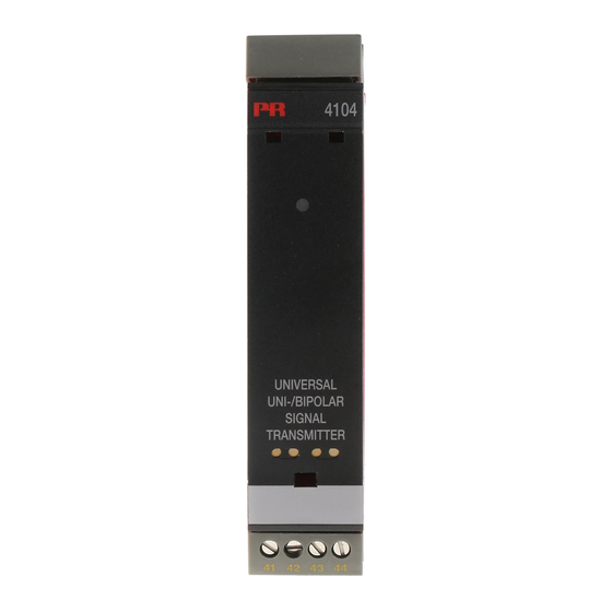
- Page 1 PERFORMANCE MADE SMARTER Product manual 4104 Universal uni-/bipolar signal transmitter T E M P E R AT U R E I . S . I N T E R FA C E S CO M M U N I C AT I O N I N T E R FA C E S...
- Page 2 6 Product Pillars to meet your every need Individually outstanding, unrivalled in combination With our innovative, patented technologies, we make signal conditioning smarter and simpler. Our portfolio is composed of six product areas, where we offer a wide range of analog and digital devices covering over a thousand applications in industrial and factory automation.
-
Page 3: Table Of Contents
Universal uni-/bipolar signal transmitter 4104 Table of contents Warning .................... -
Page 4: Warning
Warning This device is designed for connection to hazardous electric voltages. Ignoring this warning can result in severe personal injury or mechanical damage. To avoid the risk of electric shock and fire, the safety instructions of this guide must be observed and the guidelines followed. -
Page 5: Safety Instructions
Safety instructions Definitions Hazardous voltages have been defined as the ranges: 75 to 1500 Volt DC, and 50 to 1000 Volt AC. Technicians are qualified persons educated or trained to mount, operate, and also trouble-shoot technically correct and in accordance with safety regulations. Operators, being familiar with the contents of this manual, adjust and operate the knobs or potentiometers during normal operation. -
Page 6: How To Demount System 4000
When front LED flashes red or 45xx display shows AO.ER The 4104 is designed with a high safety level. Therefore, the device continuously measures the output current. If "S4-20" is selected during configuration, and output current drops to 0 mA, the 45xx display will indicate "AO.ER" and the front LED will turn red. -
Page 7: Application
Fast < 20 ms response time for measuring signals produced by torque, position, current & acceleration sensors. • User configurable bipolar or unipolar I/O means the 4104 is suitable for nearly any voltage or current conversion. • The excitation source enables measurement of two or three wire transmitters. -
Page 8: Applications
Applications Input signals: Current 2-wire Tx 3-wire Tx Voltage (Current) (±) (±) (Voltage) Output signals: + V supply Current & voltage 2-wire 10 V 10 V (±) Power connection: 21.6...253 VAC 19.2...300 VDC 4104V102-UK... -
Page 9: Pr 45Xx Display / Programming Front
Application • Communications interface for modification of operational parameters in 4104. • Can be moved from one 4104 device to another and download the configuration of the first unit to subsequent units. • When mounted in the process, the display shows process values and device status. -
Page 10: Order
Order 4104 = Universal uni-/bipolar signal transmitter Accessories 4501 = Display / programming front 4511 = Modbus communication enabler 4512 = Bluetooth communication enabler Electrical specifications Environmental conditions Operating temperature ....... . -20°C to +60°C Storage temperature . - Page 11 Input specifications Current input Signal range........±23 mA Programmable measurement ranges .
- Page 12 Observed authority requirements EMC..........2014/30/EU LVD .
-
Page 13: 45Xx Display Readout Of Input 4
Cause Check measurement of analog output AO.ER No load on the current output (only S4...20 mA)* Communications test between 45xx NO.CO Connection error and 4104 Hardware error FL.ER Error in FLASH** Configuration error CO.ER Error in FLASH** Check that saved configuration in 45xx TY.ER... -
Page 14: Connections
Connections Supply Inputs: 3-wire current 3-wire voltage Current 2-wire transmitter transmitter transmitter (±) Voltage (±) Outputs: Current 2-wire transmitter Voltage, 1 V Voltage, 10 V (±) (±) (±) (±) 4104V102-UK... -
Page 15: Block Diagram
Block diagram 4104V102-UK... -
Page 16: Configuration / Operating The Function Keys
In general When configuring the 4104, you will be guided through all parameters and you can choose the settings which fit the application. For each menu there is a scrolling help text which is automatically shown in line 3 on the display. - Page 17 Language (LANG): In the menu ”LANG” you can choose between 7 different language versions of help texts that will appear in the menu. You can choose between UK, DE, FR, IT, ES, SE and DK. Output function (OFUN): Here the output characteristics can be set to either Direct (DIR) or Inverted (INV) function. Output type and range are set in the normal programming menu.
-
Page 18: Routing Diagram
Routing diagram If no key is activated for 1 minute, the display will return to the default state 1.0 without saving configuration changes. 1 Increase value / choose next parameter 2 Decrease value / choose previous parameter 3 Save the chosen value and proceed to the next menu Hold 3 Back to previous menu / return to menu 1.0 without saving. - Page 19 -/+20 NONE -/+10 S4-20 99.99 99.99 CURR PASS 60.0 ZERO 4-20 -19.99 -19.99 VOLT ACTI DOWN 0-20 CURR 0.00 10.00 CURR 4-20 ACTI DISP.LO DISP.HI ANA.OUT O.RANGE OUT.MOD OUT.ERR RESP. Txt 8 Txt 9 Txt 10 Txt 11 Txt 13 Txt 14 Txt 15 To default state 1.0...
-
Page 20: Routing Diagram, Advanced Settings (Adv.set)
Routing diagram, advanced settings (ADV.SET) MEM, DISP, CAL, SIM, SAVE PASS, LANG, LOAD OFUN SAVE SETUP MEMORY Txt 16/1 Txt 17 A.OUT DISP TT0123 A.OUT SETUP CONTRA LIGHT TAGNO_ LINE 3 Txt 16/2 Txt 18 Txt 19 Txt 20 Txt 21 10.00 10.00 0.00... - Page 21 DE, DK, ES, FR, IT, SE, UK LANG SETUP LANGUA. Txt 16/6 Txt 31 VFUN To default state OFUN SETUP O.FUNC Txt 16/7 Txt 32 VFUN (V-shaped output function) is only available when an output range starting at zero is selected. DIR (direct) and INV (inverted) output can be combined with all selectable output ranges.
-
Page 22: Help Text Overview
Help text overview Set correct password [21] Analog output value is shown in display line 3 Enter advanced setup menu? Device TAG is shown in display line 3 Select current input [22] Calibrate Input low to process value? [23] Select voltage input Set value for low calibration point [24] Calibrate Input high to process value? -
Page 23: Document History
Document history The following list provides notes concerning revisions of this document. Rev. ID Date Notes 1240 Initial release of the product. 1302 DNV marine approval added. 1949 EAC approval added. Connection drawing and block diagram updated (input). 4104V102-UK... - Page 24 We are near you, all over the world Our trusted red boxes are supported wherever you are All our devices are backed by expert service and a 5-year business with a global reach. This means that we are warranty. With each product you purchase, you receive always nearby and know your local markets well.
- Page 25 Benefit today from PERFORMANCE MADE SMARTER PR electronics is the leading technology company specialized in making industrial process control safer, more reliable and more efficient. Since 1974, we have been dedicated to perfecting our core competence of innovating high precision technology with low power consumption.
Need help?
Do you have a question about the 4104 and is the answer not in the manual?
Questions and answers