Hobo RX3000 Series Manual
Remote monitoring station
Hide thumbs
Also See for RX3000 Series:
- Manual (33 pages) ,
- Technical manual (6 pages) ,
- Quick start quide (2 pages)
Table of Contents
Advertisement
Quick Links
HOBO® RX3000 Remote Monitoring Station Manual
HOBO RX3000 Remote
Monitoring Station
Models: RX3001-00-01 Ethernet
RX3002-00-01 Wi-Fi
RX3003-00-01 Cellular
RX3004-00-01 Cellular 4G
Included Items:
• Two plates for cable access
openings with eight
thumbscrews and one wrench
• Two rubber cable channels
• Rubber plugs
• Grease packet
• Two mounting plates with
four screws
• Grounding wire
• Two U-bolts
Required Items:
• HOBOlink
• HOBOware
®
with USB cable for RX3002 Wi-
Fi models (optional for
RX3001, RX3003, and RX3004
models)
• AC adapter (AC-U30) or solar
panel (SOLAR-xW)
Optional Items:
• Smart sensors
• Analog sensor module
(RXMOD-A1)
• Relay module (RXMOD-R1)
• RXW Manager (RXMOD-RXW-
xxx) and RXW motes
• External DC power cable
(CABLE-RX-PWR)
• Tripod kit (M-TPA or M-TPB)
• Guy wire kit (M-GWA)
• 1/2 inch stake kit (M-SKA)
• Grounding kit (M-GKA),
required if using wind speed
or wind direction smart sensor
18255-L
Find Quality Products Online at:
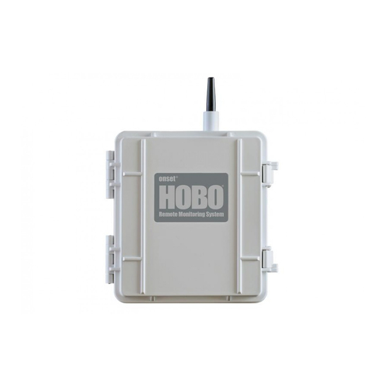
The HOBO RX3000 Remote Monitoring Station provides continuous logging for a broad range of
energy and weather monitoring applications with up to ten smart sensors, optional analog sensor
and relay modules, and wireless sensor motes. Data from the RX3000 station is transferred at
regular connection intervals to HOBOlink® web-based software where you can check the latest
conditions, view graphs, configure sensors and alarms, set up a dashboard, download your data,
or schedule data delivery via email or FTP. Inside its weatherproof enclosure, this durable station
has a built-in LCD screen to check the current system configuration and status, start and stop
logging, add and remove smart sensors, and connect to HOBOlink on demand. Up to three
individual relays can be activated on the optional relay module while the optional analog module
has four analog inputs that support excitation power, scaling, and statistics measurements. An
optional RXW Manager module is also available for the station to set up the HOBOnet Wireless
Sensor Network, which can support up to 50 motes. All three easy-to-install modules can be
configured with HOBOlink.
Specifications
Station
Operating Range
Smart Sensor Connectors
Smart Sensor Network Cable
Length
Smart Sensor Data Channels
Module Slots
Logging Rate
Time Accuracy
Battery Type/Power Source
3.7.2 or later
Rechargeable Battery
Service Life
Memory
Alarm Notification Latency
Enclosure Access
LCD
Materials
Size
Weight
Mounting
Environmental Rating
GlobalTestSupply
www.
-40° to 60°C (-40° to 140°F); no remote communications for battery
voltage less than 3.9 V DC
10
100 m (328 ft) maximum
Maximum of 15 (some smart sensors use more than one data
channel; see sensor manual for details)
2
1 second (RX3001 and RX3002) or 1 minute (RX3003 and RX3004) to
18 hours
±8 seconds per month in 0° to 40°C (32°F to 104°F) range;
±30 seconds per month in -40° to 60°C (-40° to 140°F) range
4 Volt, 10 AHr, rechargeable sealed lead-acid; external power
required using one of these options: AC power adapter (AC-U30),
solar panel (SOLAR-xW), or external power source 5 V DC to 17 V DC
with external DC power cable (CABLE-RX-PWR)
Typical 3–5 years when operated in the temperature range -20° to
40°C (-4°F to 104°F); operation outside this range will reduce the
battery service life
32 MB, 2 million measurements, continuous logging
Logging interval plus 2–4 minutes, typical
Hinged door secured by two latches with eyelets for use with user-
supplied padlocks
LCD is visible from 0° to 50°C (32° to 122°F); the LCD may react
slowly or go blank in temperatures outside this range
Outer enclosure: Polycarbonate/PBT blend with stainless steel hinge
pins and brass inserts; Inner enclosure: Polycarbonate; Gaskets:
Silicone rubber; Cable channel: EPDM rubber; Cable opening cover:
Aluminum with ABS plastic thumb screws; U-Bolts: Steel with zinc
dichromate finish
18.6 x 18.1 x 11.8 cm (7.3 x 7.1 x 4.7 in.); see diagrams on next page
2.2 kg (4.85 lb)
3.8 cm (1.5 inch) mast or wall mount
Weatherproof enclosure, NEMA 4X (requires proper installation of
cable channel system)
.com
sales@GlobalTestSupply.com
Advertisement
Table of Contents

Related Manuals for Hobo RX3000 Series


Summary of Contents for Hobo RX3000 Series
- Page 1 HOBO® RX3000 Remote Monitoring Station Manual The HOBO RX3000 Remote Monitoring Station provides continuous logging for a broad range of energy and weather monitoring applications with up to ten smart sensors, optional analog sensor and relay modules, and wireless sensor motes. Data from the RX3000 station is transferred at regular connection intervals to HOBOlink®...
- Page 2 HOBO RX3000 Remote Monitoring Station Manual Specifications (continued) The CE Marking identifies this product as complying with all relevant directives in the European Union (EU) See last page RX3002: FCC ID R68XPICOW, IC ID 3867A-XPICOW RX3003: FCC ID QIPEHS6, IC ID 7830A-EHS6; approved for use in...
-
Page 3: Table Of Contents
HOBO RX3000 Remote Monitoring Station Manual Specifications (continued) Optional Relay Module (RXMOD-R1) Relays Three independent relays Current 1 Amp max Optional RXW Manager Module (RXMOD-RXW-xxx) Operating Temperature -25° to 60°C (-13° to 140°F) Range Relay Module (RXMOD-R1) Radio Power 12.6 mW (+11 dBm) non-adjustable Transmission Range At least 304.8 m (1,000 ft) line of sight at 1.8 m (6 ft) from the ground,... -
Page 4: Device Components And Operation
HOBO RX3000 Remote Monitoring Station Manual Device Components and Operation Antenna Connect/ Start/ (RX3003) Search Stop Select Station Door Button Button Button LCD Screen SIM Card (RX3003) or Micro SIM Card (RX3004) Vent Grounding Smart Sensor USB Port Module Slots... -
Page 5: Lcd Operation
HOBO RX3000 Remote Monitoring Station Manual LCD Operation This example shows all symbols illuminated on the LCD screen with an overview of what each section of the LCD represents. Refer to the table below for details about each section and associated symbols. - Page 6 HOBO RX3000 Remote Monitoring Station Manual This part of the LCD shows the number of channels and other information about each module. It also shows general device Channel and information. Press the Select button to scroll through four screens: the main screen, smart sensors screen, Module 1, and Device Module 2 screens.
-
Page 7: Setting Up The Station
HOBO RX3000 Remote Monitoring Station Manual Notes on LCD Operation: If you are installing an RXW Manager module, plug the cable from the RXW Manager mote into the jack on the • The LCD will turn off after 5 minutes of inactivity. Press module, making sure the cable is inserted through the any button to turn the LCD back on. -
Page 8: Check And Configure Device Communications
HOBO RX3000 Remote Monitoring Station Manual c. Once the battery cable is plugged in, “Initializing some features. Select Domain networks and click Allow System” will flash on the LCD. A checkmark appears next Access.) to “System” after the station initialization is complete. -
Page 9: Plug In And Search For Any Smart Sensors
HOBO RX3000 Remote Monitoring Station Manual e. The station uses DHCP by default. If your network uses The station will search for all connected smart sensors DHCP, skip this step. and show the number of channels after a few seconds. -
Page 10: Connect Analog Sensors Or Relay Devices
HOBO RX3000 Remote Monitoring Station Manual c. Watch the mote LCD during the process of joining the c. Insert the appropriate wire into the screw terminal (see network. the pinout table below). The wire should be trimmed to expose 0.25 inches ±0.04 inches of bare wire. -
Page 11: Configure The Station In Hobolink
HOBO RX3000 Remote Monitoring Station Manual c. Click Save or click Next. Press the Select button to Smart Sensors Logging and Configuration Press the Connect button return to the main LCD screen You can configure both the global settings that affect all smart 10. - Page 12 HOBO RX3000 Remote Monitoring Station Manual h. Click Save. You can also click Next to move from one also automatically be applied to any mote sensors smart sensor to the next. without a default label. f. Click Save or click to Next to move to either the next mote (if it was a repeater) or the sensor measurement type for that mote.
-
Page 13: Start Logging
HOBO RX3000 Remote Monitoring Station Manual minimum, maximum, average, and standard deviation. j. Select the sensor/input type, which is needed to set the The selected statistics will be calculated between each voltage or current range for the analog input. logging interval at the sampling interval rate you select. -
Page 14: Viewing Data In Hobolink
HOBO RX3000 Remote Monitoring Station Manual Logging will not begin until the next time the station 4. Click Save to keep these settings for future use or click connects to HOBOlink. Press the Connect button on the Export Data to export immediately. -
Page 15: Sensor Alarms
HOBO RX3000 Remote Monitoring Station Manual and then select “Send on Clear Also” if you want an A red alarm symbol appears next to that sensor in HOBOlink email or text when these alarms clear as well. when it trips. An alarm symbol will also appear on the LCD. -
Page 16: Adding Or Removing Smart Sensors
HOBO RX3000 Remote Monitoring Station Manual Adding or Removing Smart Sensors To add or remove smart sensors from the station: 1. If the station is currently logging, press the Stop button to stop it. 2. Press the Connect button and wait for the station to connect to HOBOlink so that all the latest data is offloaded before changing smart sensors. -
Page 17: Adding Or Removing Motes
HOBO RXW Manager is installed in the left slot (module 1) or twice if it is installed on the right slot (module 2). Once the mote has finished joining This network connection the network, the “x”... -
Page 18: Managing Connections To Hobolink
HOBO RX3000 Remote Monitoring Station Manual b. Select the mote serial number or name from the extra connections while the station is in night mode will not Configuration menu as shown in the following example. cause a shift in the connection schedule. - Page 19 HOBO RX3000 Remote Monitoring Station Manual • Make sure the station remains in a vertical position once it • Make sure each sensor mote and repeater is positioned so is placed in its deployment location. If it is mounted that the built-in solar panel receives optimal sunlight horizontally, the battery could be damaged over time as it throughout each season as shown.
-
Page 20: Installing The Grounding Wire
HOBO RX3000 Remote Monitoring Station Manual • Make sure the mote door is closed, with both latches fully locked to ensure a watertight seal. • Consider using a 3/16 inch padlock to restrict access to the mote. With the mote door closed, hook a padlock through the eyelet on the right side of the door and lock it. -
Page 21: Care And Maintenance
HOBO RX3000 Remote Monitoring Station Manual Care and Maintenance Important: The cable diameter must be 4.0 mm (0.156 in.) to fit through one of the five smaller holes or 6.4 The station is designed for outdoor use, but should be mm (0.25 in.) to fit through one of the five larger holes... -
Page 22: Battery Information
HOBO RX3000 Remote Monitoring Station Manual Fault Code # Description Action to Take Removing Smart Sensors). Also check that the smart sensor cables are ok. Analog Check the analog sensor connection Excitation and the excitation settings for the Bus Fault sensor in HOBOlink. - Page 23 ISM radio wave radiated devices. © 2015–2019 Onset Computer Corporation. All rights reserved. Onset, HOBO, and HOBOlink are trademarks or registered trademarks of Onset Computer Corporation. All other trademarks are the property of their respective companies.
- Page 24 The CE Marking identifies this product as complying with all relevant directives in the European Union (EU). * A single HOBO station can accommodate 15 data channels and up to 100 m (328 ft) of smart sensor cable (the digital communications portion of the sensor cables).
- Page 25 Do not use hot water, organic solvents, or detergents. Dry before use. © 2008–2018 Onset Computer Corporation. All rights reserved. Onset and HOBO are trademarks or registered trademarks of Onset Computer Corporation. All other trademarks are the property of their respective companies.
- Page 26 The CE Marking identifies this product as complying with all relevant directives in the European Union (EU). * A single HOBO station can accommodate 15 data channels and up to 100 m (328 ft) of smart sensor cable (the digital communications portion of the sensor cables).
- Page 27 Wind Speed Smart Sensor (S-WSB-M003) Manual a. Loosen the tri-clamp bolts and raise or lower the entire Mounting mast so that the wind sensor is close to the desired height. Make sure there is at least 5 cm (2 inches) of Placement and Mounting Considerations mast extending below the lower tri-clamp.
- Page 28 © 2002–2017 Onset Computer Corporation. All rights reserved. Onset and HOBO are trademarks or registered trademarks of Onset Computer Corporation. Teflon is a registered trademark of DuPont. All other trademarks are the property of their respective companies.
- Page 29 The CE Marking identifies this product as complying with all relevant directives in the European Union (EU). * A single HOBO station can accommodate 15 data channels and up to 100 m (328 ft) of smart sensor cable (the digital communications portion of the sensor cables).
- Page 30 Wind Direction Smart Sensor (S-WDA-M003) Manual 4. Adjust the height of the sensor in the cross arm as Mounting necessary using one of the following methods and then tighten the nut and bolt until the cross arm just starts to Placement and Mounting Considerations deform.
- Page 31 Wind Direction Smart Sensor (S-WDA-M003) Manual 2. Secure the sensor cable with cable ties. Make sure there are drip loops on both sides of the smart sensor housing, which must also be mounted horizontally, as described under Placement and Mounting Considerations. North marking Mounting rod Hose clamps...
- Page 32 © 2011–2017 Onset Computer Corporation. All rights reserved. Onset and HOBO are trademarks or registered trademarks of Onset Computer Corporation. All other trademarks are the property of their respective companies.
- Page 33 Note: This shield does not protect sensors from light reflected from below the shield at some angles. Avoid deploying this shield next to reflective surfaces if possible. © 2016–2017 Onset Computer Corporation. All rights reserved. Onset and HOBO are registered trademarks of Onset Computer Corporation. All other trademarks are the property of their respective companies.
Need help?
Do you have a question about the RX3000 Series and is the answer not in the manual?
Questions and answers