Table of Contents
Advertisement
Advertisement
Table of Contents

Related Manuals for Yamaha YK-X Series


Summary of Contents for Yamaha YK-X Series
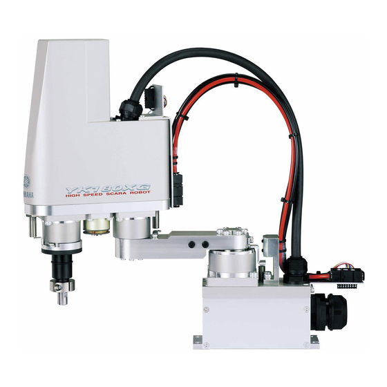
- Page 1 YK-X series YAMAHA SCARA ROBOT YK-XG User’s Manual ENGLISH E35-Ver. 1.08...
- Page 3 Before using the robot (Be sure to read the following notes.) At this time, our thanks for your purchase of this YAMAHA YK-XG series SCARA robot. 1. Please be sure to perform the following tasks before using the robot. Failing to perform the tasks below will require re-teaching of the robot since the origin position cannot be set to the same previous position.
- Page 4 Set the origin position while referring to absolute reset methods in "3. Adjusting the origin" in Chapter 4 of this manual and in "Absolute Reset" of the "YAMAHA Robot Controller User's Manual". Set the origin position with the absolute reset.
- Page 5 Introduction The YAMAHA YK-XG series robots are SCARA type industrial robots devel- oped based on years of YAMAHA experience and achievements in the automa- tion field as well as efforts to streamline our in-house manufacturing systems. The YK-XG series robots have a two-joint manipulator consisting of an X-axis arm and a Y-axis arm, and are further equipped with a vertical axis (Z-axis) and a rotating axis (R-axis) at the tip of the manipulator.
- Page 6 MEMO...
-
Page 7: Table Of Contents
CONTENTS CHAPTER 1 Using the Robot Safely Safety Information ..................1-1 Essential Caution Items ................1-2 Special Training for Industrial Robot Operation ...........1-8 Robot Safety Functions................1-9 Safety Measures for the System ..............1-10 Trial Operation ................... 1-11 Work Within the Safeguard Enclosure ............1-12 Automatic Operation ..................1-13 Adjustment and Inspection.................1-13 10 Repair and Modification ................1-13... - Page 8 User Wiring and User Tubing ..............3-12 Attaching The End Effector ................3-16 R-axis tolerable moment of inertia and acceleration coefficient ......3-16 6-1-1 Acceleration coefficient vs. moment of inertia (YK500XG) ........3-17 6-1-2 Acceleration coefficient vs. moment of inertia (YK600XG) ........3-17 6-1-3 Acceleration coefficient vs.
- Page 9 CHAPTER 5 Periodic Inspecition Overview ......................5-1 Precautions ....................5-2 Daily Inspection....................5-3 Six-Month Inspection ...................5-5 Replacing the Harmonic Drive ..............5-9 Replacement period ....................5-9 Basic replacement procedure for harmonic drive and precautions ......5-10 5-2-1 YK500XG, YK600XG, YK600XGH, YK700XG, YK800XG, YK900XG, YK1000XG ... 5-12 CHAPTER 6 Increasing the robot operating speed Increasing the robot operating speed ............6-1 CHAPTER 7 Specifications...
- Page 10 MEMO...
- Page 11 CHAPTER Using the Robot Safely Safety Information ....................1-1 Essential Caution Items ...................1-2 Special Training for Industrial Robot Operation ..........1-8 Robot Safety Functions ..................1-9 Safety Measures for the System ..............1-10 Trial Operation....................1-11 Work Within the Safeguard Enclosure ............1-12 Automatic Operation ..................1-13 Adjustment and Inspection ................1-13 10 Repair and Modification .................1-13 11 Warranty ......................1-14...
- Page 12 MEMO...
-
Page 13: Chapter 1 Using The Robot Safely
Industrial robots are highly programmable, mechanical devices that provide a large degree of freedom when performing various manipulative tasks. To ensure correct and safe use of YAMAHA industrial robots, carefully read this manual and make yourself well acquainted with the contents. FOLLOW THE WARN- INGS, CAUTIONS AND INSTRUCTIONS INCLUDED IN THIS MANUAL. -
Page 14: Essential Caution Items
CHAPTER 1 Using the Robot Safely Essential Caution Items Particularly important cautions for handling or operating the robot are described below. In addition, safety information about installation, operation, inspection and maintenance is provided in each chapter. Be sure to comply with these in- structions to ensure safe use of the robot. - Page 15 CHAPTER 1 Using the Robot Safely WARNING Moving parts can pinch or crush. Keep hands away from robot arms. ■Fig. 1-2 Warning label 2 (3) Follow the instructions on warning labels and in this manual. Warning label 3 (Fig. 1-3) is affixed to the robot. See Fig. 2-2 for the loca- tions of warning labels.
- Page 16 CHAPTER 1 Using the Robot Safely (5) Do not use the robot in environments containing inflammable gas, etc. WARNING • This robot was not designed for operation in environments where inflamma- ble or explosive substances are present. • Do not use the robot in environments containing inflammable gas, dust or liquids.
- Page 17 CHAPTER 1 Using the Robot Safely (9) Be cautious of possible Z-axis movement when the controller is turned off or emergency stop is triggered. (2-axis robots with air-driven Z-axis) WARNING The Z-axis moves up when the power to the controller or PLC is turned off, the program is reset, emergency stop is triggered, or air is supplied to the solenoid valve for the Z-axis air cylinder.
- Page 18 • Never touch any internal parts of the controller. For precautions on handling the controller, refer to the "YAMAHA Robot Con- troller User's Manual". (15) Consult us for corrective action when the robot is damaged or malfunction occurs.
- Page 19 CHAPTER 1 Using the Robot Safely (17) Do not remove, alter or stain the warning labels. WARNING If warning labels are removed or difficult to see, necessary cautions may not be taken, resulting in an accident. • Do not remove, alter or stain the warning labels on the robot. •...
-
Page 20: Special Training For Industrial Robot Operation
CHAPTER 1 Using the Robot Safely Special Training for Industrial Robot Opera- tion Companies or factories using industrial robots must make sure that every person, who handles the robot such as for teaching, programming, movement check, in- spection, adjustment and repair, has received appropriate training and also has the skills needed to perform the job correctly and safely. -
Page 21: Robot Safety Functions
CHAPTER 1 Using the Robot Safely Robot Safety Functions (1) Overload detection This function detects an overload applied to the motor and shuts off the servo power. If an overload error occurs, take the following measures. 1. Insert a timer in the program. 2. -
Page 22: Safety Measures For The System
CHAPTER 1 Using the Robot Safely Safety Measures for the System Since the robot is commonly used in conjunction with an automated system, dan- gerous situations are more likely to occur from the automated system than from the robot itself. Accordingly, appropriate safety measures must be taken on the part of the system manufacturer according to the individual system. -
Page 23: Trial Operation
CHAPTER 1 Using the Robot Safely Trial Operation After making installations, adjustments, inspections, maintenance or repairs to the robot, make a trial run using the following procedures. (1) If a safeguard enclosure has not yet been provided right after installation of the robot, rope off or chain off around the movement area of the manipulator in place of the safeguard enclosure, and observe the following points. -
Page 24: Work Within The Safeguard Enclosure
CHAPTER 1 Using the Robot Safely Work Within the Safeguard Enclosure (1) When work is required inside the safeguard enclosure, always turn off the controller and place a sign indicating that the robot is being adjusted or serv- iced in order to keep any other person from touching the controller switch or operation panel, except for the following cases. -
Page 25: Automatic Operation
CHAPTER 1 Using the Robot Safely Automatic Operation Automatic operation described here includes all operations in AUTO mode. (1) Check the following before starting automatic operation. 1. No one is within the safeguard enclosure. 2. The programming unit and tools are in their specified locations. 3. -
Page 26: Warranty
CHAPTER 1 Using the Robot Safely Warranty The YAMAHA robot and/or related product you have purchased are warranted against the defects or malfunctions as described below. Warranty description : If a failure or breakdown occurs due to defects in materials or workmanship in the genuine... - Page 27 OR WARRANTIES ARISING FROM A COURSE OF DEALING OR USAGE OF TRADE. YAMAHA MOTOR CO., LTD. SOLE LIABILITY SHALL BE FOR THE DE- LIVERY OF THE EQUIPMENT AND YAMAHA MOTOR CO., LTD. SHALL NOT BE LIABLE FOR ANY CONSEQUENTIAL DAMAGES (WHETHER ARISING FROM CONTRACT, WARRANTY, NEGLIGENCE OR STRICT LIABILITY).
-
Page 28: Ce Marking
CHAPTER 1 Using the Robot Safely CE Marking When the YAMAHA robots are exported to or used in EU (European Union) countries, refer to the separate "YAMAHA Robot Controller User's Manual" or "CE marking manual" for related information about CE marking. -
Page 29: Chapter 2 Functions
CHAPTER Functions Robot Manipulator ....................2-1 Robot Controller ....................2-3 Robot initialization number list .................2-4... - Page 30 MEMO...
-
Page 31: Robot Manipulator
CHAPTER 2 Functions Robot Manipulator The YK-XG series robots are available in 4-axis models having an X/Y-axis arm (equivalent to human arm) and a Z/R-axis (equivalent to human wrist). With these 4 axes, the YK-XG series robots can move as shown in Fig. 2-1. By attaching different types of end effector (gripper) to the end of the arm, a wide range of tasks can be performed with high precision at high speeds. - Page 32 CHAPTER 2 Functions User tubing 1 (φ6 black) Eyebolt installation position User tubing 2 (φ6 red) User tubing 3 (φ6 blue) D-sub connector for user wiring (No.1 to 20) Machine harness Ball screw Y-axis motor R-axis motor Y-axis arm Y-axis mechanical stopper X-axis speed reduction gear X-axis arm X-axis movable mechanical stopper...
-
Page 33: Robot Controller
CHAPTER 2 Functions Robot Controller The YK-XG series robot comes supplied with a robot controller RCX142. For more details, refer to the separate "YAMAHA Robot Controller User's Manual". RCX142 MOTOR OP.1 OP.3 MODEL. SER. NO. MANUFACTURED FACTORY AUTOMATION EQUIPMENT MADE IN JAPAN 注意... -
Page 34: Robot Initialization Number List
CHAPTER 2 Functions Robot initialization number list The YK-XG series robots are initialized for optimum setting (default setting) according to the robot model prior to shipping. The robot controllers do not have to be reinitialized during normal operation. However, if for some reason the con- troller must be reinitialized, proceed while referring to the list below. - Page 35 CHAPTER Installation Robot Installation Conditions ................3-1 Installation environments ....................3-1 Installation base ......................3-2 Installation ......................3-4 Unpacking........................3-4 Checking the product ...................... 3-5 Moving the robot ......................3-6 2-3-1 Moving the YK500XG, YK600XG, YK600XGH, YK700XG, YK800XG, YK900XG, YK1000XG ........................3-6 Installing the robot ......................
- Page 36 MEMO...
-
Page 37: Chapter 3 Installation
Working space repair, etc.) For detailed information on how to install the robot controller, refer to the sepa- rate "YAMAHA Robot Controller User's Manual". WARNING • Avoid installing the robot in locations where the ambient conditions may ex- ceed the allowable temperature or humidity, or in environments where water, corrosive gases, metallic powder or dust are generated. -
Page 38: Installation Base
CHAPTER 3 Installation Installation base WARNING • Install the robot on a horizontal surface, with the base mount section facing down. If installed by other methods with the base mount section not facing down, grease might leak from the reduction gear unit. •... - Page 39 3) Tap holes into the surface of the installation base. For machining dimensions and positions, refer to the external view and dimensions shown in the catalog or website (www.yamaha-motor.co.jp/global/industrial/robot). 4) Securely fix the installation base on the floor with anchor bolts.
-
Page 40: Installation
CHAPTER 3 Installation Installation Unpacking WARNING The robot and controller are heavy. Take sufficient care not to drop them during moving or unpacking as this may damage the equipment or cause bodily injury. CAUTION When moving the robot or controller by equipment such as a folklift that require a license, only properly qualified personnel may operate it. -
Page 41: Checking The Product
The following configurations are typical examples, so please check that the prod- uct is as specified in your order. CAUTION If there is any damage due to transportation or insufficient parts, please notify your YAMAHA sales office or dealer immediately. Controller : RCX142 Robot... -
Page 42: Moving The Robot
CHAPTER 3 Installation Moving the robot WARNING Serious injury may occur if the robot falls and pins someone under it. • Do not allow any part of your body to enter the area beneath the robot during work. • Always wear a helmet, safety shoes and gloves during work. To check the mass of each robot, refer to "1-1 Basic specifications"... - Page 43 CHAPTER 3 Installation 4) Screw the two eyebolts through washers into the upper surface of the X-axis arm. 5) Wind the robot cable around the upper part of the robot base so that it does not hang up on the base mount, then fasten the cable end with adhesive tape. 6) Prepare two looped ropes with the same length to allow a good lifting balance, then pass each rope through each eyebolt and catch it on the hoist hook.
-
Page 44: Installing The Robot
CHAPTER 3 Installation Installing the robot Install the robot securely with the four hex socket head bolts as shown in Fig. 3-5. WARNING When installing the robot, be sure to use the specified size and quantity of bolts that match the depth of tapped holes in the installation base, and securely tighten the bolts to the correct torque. -
Page 45: Protective Bonding
3) For details on protective bonding on the robot body to comply with CE Mark- ing, follow the instructions on protective bonding explained in the "YAMAHA Robot Controller User's Manual" or "CE Marking manual". 4) Use a ground cable with a conductor wire cross section of at least 2.0mm... - Page 46 CHAPTER 3 Installation Ground symbol M4 Ground terminal Fig. 3-6 Ground terminal 3-10...
-
Page 47: Robot Cable Connection
Robot Cable Connection The robot cable is pre-connected to the YK-XG series robot. For details on con- nections to the robot controller, refer to Fig. 3-7 and the "YAMAHA Robot Con- troller User's Manual". After making connections, check the operation while re- ferring to "6 Trial operation"... -
Page 48: User Wiring And User Tubing
2) A D-sub connector for user wiring and a bulkhead union for user tubing are provided one each on the arm side and pedestal side. For the locations, refer to the external view and dimensions shown in the catalog or website (www.yamaha-motor.co.jp/global/industrial/robot). 3-12... - Page 49 CHAPTER 3 Installation 3) Signal wiring connections in the machine harness 1. YK500XG, YK600XG Connector pins 1 to 20 can be used. Pin 25 is connected to a shield wire and cannot be used as a signal wire. Signal Connector Connection Connector Color...
- Page 50 CHAPTER 3 Installation 4) As shown in Fig. 3-8, solder the user cable wires to the D-sub connector (supplied with the robot). Reattach the hood to the D-sub connector after soldering, then plug it into the user wiring connector. The connector pinouts as viewed from the solder side are shown below. Hood Soldering Cable to be...
- Page 51 CHAPTER 3 Installation CAUTION • The D-sub connector supplied with the robot should be connected to the arm side by pin contact, and to the pedestal side by socket contact. Use caution at these points when soldering. • Be sure to use the D-sub connector and hood which are supplied with the robot.
-
Page 52: Attaching The End Effector
To make settings for the tip mass and acceleration coefficient, refer to the separate "YAMAHA Robot Controller User's Manual". 3) Methods for calculating the moment of inertia of the load are shown in Sec- tion 6-2, however, it is not easy to precisely figure out these values. -
Page 53: Acceleration Coefficient Vs. Moment Of Inertia (Yk500Xg)
CHAPTER 3 Installation 6-1-1 Acceleration coefficient vs. moment of inertia (YK500XG) 0.04 (0.4) 0.05 0.15 0.25 (kgm (kgm Fig. 3-9 m=1 to 10kg 6-1-2 Acceleration coefficient vs. moment of inertia (YK600XG) 0.03 (0.3) 0.05 0.15 0.25 (kgm (kgm Fig. 3-10 m=1 to 10kg 3-17... -
Page 54: Acceleration Coefficient Vs. Moment Of Inertia (Yk600Xgh)
CHAPTER 3 Installation 6-1-3 Acceleration coefficient vs. moment of inertia (YK600XGH) 0.03 (0.3) (kgm 10.0 (kgfcmsec Fig. 3-11 m=1 to 20kg 6-1-4 Acceleration coefficient vs. moment of inertia (YK700XG, YK800XG) 0.02 (0.2) (kgm 10.0 (kgfcmsec Fig. 3-12 m=1 to 20kg 3-18... -
Page 55: Acceleration Coefficient Vs. Moment Of Inertia (Yk900Xg, Yk1000Xg)
CHAPTER 3 Installation 6-1-5 Acceleration coefficient vs. moment of inertia (YK900XG, YK1000XG) 0.07 (0.7) (kgm 10.0 (kgfcmsec Fig. 3-13 m=1 to 20kg 3-19... -
Page 56: Equation For Moment Of Inertia Calculation
CHAPTER 3 Installation Equation for moment of inertia calculation Usually the R axis load is not a simple form, and the calculation of the moment of inertia is not easy. As a method, the load is replaced with several factors that resemble a simple form for which the moment of inertia can be calculated. - Page 57 CHAPTER 3 Installation 3) Moment of inertia for cylinder (part 2) The equation for the moment of inertia for a cylinder that has a rotation center such as shown in Fig. 3-16 is given below. ρπ D h (kgm ρπ D h (kgfcmsec ...
- Page 58 CHAPTER 3 Installation 5) When the object's center line is offset from the rotation center. The equation for the moment of inertia, when the center of the cylinder is offset by the distance "x" from the rotation center as shown in Fig. 3-18, is given as follows.
-
Page 59: Example Of Moment Of Inertia Calculation
CHAPTER 3 Installation Example of moment of inertia calculation Let's discuss an example in which the chuck and workpiece are at a position offset by 10cm from the R-axis by a stay, as shown in Fig. 3-21. The moment of inertia is calculated with the following three factors, assuming that the load mate- rial is steel and its density ρ... - Page 60 CHAPTER 3 Installation 2) Moment of inertia of the chuck R-axis When the chuck form resem- bles that shown in Fig. 3-23, the weight of the chuck (Wc) Wc = 0.0078 × 2 × 4 × 6 = 0.37 (kgf) The moment of inertia of the chuck (Jc) is then calculated from Eq.
-
Page 61: Attaching The End Effector
CHAPTER 3 Installation Attaching the end effector WARNING • Before attaching the end effector, be sure to turn off the controller. • When the end effector is attached by slot clamping, always observe the con- ditions listed in Table 3-2. If these are ignored, the end effector may come loose and fly off during robot operation, resulting in an accident or injury. - Page 62 CHAPTER 3 Installation Never loosen this bolt. Spline shaft (hollow diameter φ14) End effector attachment area φ20 h7 -0.021 M16×2, depth 20 YK500XG, YK600XG Never loosen this bolt. Spline shaft (hollow diameter φ18) End effector attachment area φ25 h7 -0.021 M20×2.5, depth 20 YK600XGH, YK700XG, YK800XG, YK900XG, YK1000XG Fig.
- Page 63 CHAPTER 3 Installation Table 3-1 Mmax kgfm kgfm Robot Model YK500XG YK600XG YK600XGH YK700XG YK800XG YK900XG YK1000XG WARNING • The end effector attachment must have adequate strength to withstand the loads listed in Table 3-1. If too weak, the attachment may break during robot operation and fragments fly off causing accidents or injuries.
- Page 64 CHAPTER 3 Installation Hole diameter Bolt Slot Spline shaft End effector or stay Fig. 3-27 3-28...
-
Page 65: Gripping Force Of End Effector
CHAPTER 3 Installation Gripping force of end effector The gripping force of the end effector must have a sufficient extra margin of strength versus the workpiece weight and reaction force applied to the workpiece during robot operation. The reaction force applied to the workpiece during opera- tion can be calculated from the acceleration applied to the end effector attach- ment. -
Page 66: Limiting The Movement Range With X-Axis Mechanical Stoppers
CHAPTER 3 Installation Limiting the Movement Range with X-Axis Mechanical Stoppers In the YK-XG Series, the movement range can be limited by changing the X-axis mechanical stopper positions. (See Fig. 3-29.) The Y-axis mechanical stopper positions are fixed and cannot be changed. When the robot is shipped from the factory, the movement range is set to the maximum. -
Page 67: Yk500Xg, Yk600Xg, Yk600Xgh, Yk700Xg, Yk800Xg, Yk900Xg, Yk1000Xg
Table 3-5 Robot Model Bolt size Tightening torque (kgfcm) Tightening torque (Nm) YK500XG,YK600XG 37.2 YK600XGH, YK700XG, YK800XG, 45.0 YK900XG, YK1000XG Use only YAMAHA genuine bolts or JIS B 1176 hex socket head bolts (strength class: JIS B 1051 12.9). 3-31... - Page 68 CHAPTER 3 Installation Y-axis mechanical stopper X-axis movable mechanical stopper 12° 43° 87° Fig. 3-29 X-axis movable mechanical stopper position Screw plug X-axis stopper bolt Washer : YK500XG, YK600XG (1 washer) YK600XGH, YK700XG YK800XG, YK900XG, YK1000XG (2 washers) Fig. 3-30 Changing the X-axis mechanical stopper position 3-32...
-
Page 69: Working Envelope And Mechanical Stopper Positions For Maximum Working Envelope
CHAPTER 3 Installation Working Envelope and Mechanical Stopper Positions for Maximum Working Envelope Working envelope of each robot and mechanical stopper positions for the maxi- mum working envelope are shown in Fig. 3-31 to Fig. 3-37. Z300mm stroke Z200mm stroke Z-axis upper-end 137.6 ±2 mechanical stopper position... - Page 70 CHAPTER 3 Installation Z300mm stroke Z200mm stroke Z-axis upper-end 137.6 ±2 mechanical stopper position 8mm rise during Z-axis return-to-origin Z-axis lower end mechanical stopper position Working envelope Interference position (a) Base front panel Maximum movement range Interference position (a) Base front panel (b) Base side panel X-axis mechanical stopper: 132°...
- Page 71 CHAPTER 3 Installation Z400mm stroke Z200mm stroke 208.7±2 Z-axis upper-end mechanical stopper position 6mm rise during Z-axis return-to-origin Z-axis lower end mechanical stopper position 97° 97° 96° 96° Working envelope Interference position (a) Base front panel Maximum movement range Interference position (a) Base front panel (b) Base side panel X-axis mechanical stopper: 132°...
- Page 72 CHAPTER 3 Installation Z400mm stroke Z200mm stroke 208.7±2 Z-axis upper-end mechanical stopper position 6mm rise during Z-axis return-to-origin Z-axis lower end mechanical stopper position Working envelope Interference position (a) Base front panel Maximum movement range Interference position (a) Base front panel (b) Base side panel X-axis mechanical stopper: 132°...
- Page 73 CHAPTER 3 Installation Z400mm stroke Z200mm stroke 208.7±2 Z-axis upper-end mechanical stopper position 6mm rise during Z-axis return-to-origin Z-axis lower end mechanical stopper position Working envelope Interference position (a) Base front panel Maximum movement range Interference position (a) Base front panel (b) Base side panel X-axis mechanical stopper: 132°...
- Page 74 CHAPTER 3 Installation Z400mm stroke Z200mm stroke 208.7±2 Z-axis upper-end mechanical stopper position 6mm rise during Z-axis return-to-origin Z-axis lower end mechanical stopper position Working envelope Interference position (a) Base front panel Maximum movement range Interference position (a) Base front panel (b) Base side panel X-axis mechanical stopper: 132°...
- Page 75 CHAPTER 3 Installation Z400mm stroke Z200mm stroke 208.7±2 Z-axis upper-end mechanical stopper position 6mm rise during Z-axis return-to-origin Z-axis lower end mechanical stopper position Working envelope Interference position (a) Base front panel Maximum movement range Interference position (a) Base front panel (b) Base side panel X-axis mechanical stopper: 132°...
- Page 76 CHAPTER 3 Installation Here, working envelope and mechanical stopper positions for the maximum work- ing envelope of a robot are described using the YK500XG as an example. Refer to Fig. 3-31 YK500XG. Other robot models are the same. 1) X and Y axes 1.
- Page 77 CHAPTER 3 Installation 4) Robot overrun during impacts with mechanical stopper A urethane damper is installed to absorb the shock when an impact occurs with the mechanical stopper, so a certain amount of overrun occurs when the robot strikes the mechanical stopper. Use caution and take overrun into ac- count since the end effector may interfere with the robot body and peripheral equipment or the robot body may interfere with the peripheral equipment.
- Page 78 MEMO 3-42...
- Page 79 CHAPTER Adjustment Overview ......................4-1 Safety Precautions ...................4-1 Adjusting the origin ...................4-2 Absolute reset method....................4-3 3-1-1 Sensor method (X-axis, Y-axis, and R-axis) ..............4-3 3-1-2 Stroke end method (Z-axis) ....................4-3 Machine reference ......................4-4 Absolute reset procedures....................4-5 3-3-1 Sensor method (X-axis, Y-axis, and R-axis) ..............
- Page 80 MEMO...
-
Page 81: Chapter 4 Adjustment
CHAPTER 4 Adjustment Overview YAMAHA robots have been completely adjusted at the factory or by the sales representative before shipment, including the origin position adjustment. If the operating conditions are changed and the robot must be adjusted, then follow the procedures described in this chapter. -
Page 82: Adjusting The Origin
The robot is shipped from the factory in condition "c" (below), so please perform absolute reset after installing the robot. For more details on abso- lute reset, refer to "Absolute Reset" in Chapter 4 of the "YAMAHA Robot Con- troller User's Manual". -
Page 83: Absolute Reset Method
CHAPTER 4 Adjustment Absolute reset method 3-1-1 Sensor method (X-axis, Y-axis, and R-axis) In the sensor method, the target axis is automatically operated for the absolute reset, and the absolute reset is performed at the position where the proximity sensor provided on the target axis detects the detection area (dog). The absolute reset in the sensor method can be executed with the teaching pendant (MPB), RS- 232C communication, and dedicated input. -
Page 84: Machine Reference
CHAPTER 4 Adjustment Machine reference The YK-XG series position detectors are resolvers that have four positions where absolute reset can be performed per motor revolution. If the sensor method is used for the absolute reset, the origin position will be set at the positions where absolute reset can be performed soon after the origin sensor reacts to the dog (the origin signal is detected). -
Page 85: Absolute Reset Procedures
Never enter within the robot movement range during absolute reset. The operation procedure using the MPB is described next. (Press the ESC key on the MPB if you want to return to the preceding step.) See the "YAMAHA Robot Controller User's Manual" for information on operating the robot controller. - Page 86 CHAPTER 4 Adjustment 8) After the absolute reset is completed, check that the machine reference value displayed on the MPB is between 40 and 60 (recommended range). If the machine reference value is outside the recommended range, then the next absolute reset may not be properly performed.
-
Page 87: Stroke End Method (Z-Axis)
Never enter within the robot movement range during absolute reset. The operation procedure using the MPB is described next. (Press the ESC key on the MPB if you want to return to the preceding step.) See the "YAMAHA Robot Controller User's Manual" for information on operat-ing the robot controller. -
Page 88: Changing The Origin Position And Adjusting The Machine Reference
CHAPTER 4 Adjustment Changing the origin position and adjusting the machine reference CAUTION • If the origin position has been changed, then the absolute reset must be performed, the machine reference must be adjusted, and the standard coor- dinate and point data must be reset. •... -
Page 89: Sensor Method
CHAPTER 4 Adjustment 3-4-1 Sensor method 3-4-1-1 YK500XG, YK600XG, YK600XGH, YK700XG, YK800XG, YK900XG, YK1000XG 1-1 Adjusting the X-axis machine reference CAUTION The origin position may change due to machine reference adjustment. If it oc- curs, you must set point data again. The adjustment method for the X-axis machine reference is as follows. - Page 90 CHAPTER 4 Adjustment 11) Move the X-axis origin sensor stay in the following manner and then secure it with the bolts. NOTE • When the machine reference is less than 40%, move the stay in direction q: See Fig. 4-3 (b). •...
- Page 91 CHAPTER 4 Adjustment X-axis origin sensor stay X-axis origin sensor Cover Bolt Fig. 4-3 (b) 4-11...
- Page 92 CHAPTER 4 Adjustment 1-2 Changing the X-axis origin position The X-axis origin position can be changed to any position in the range from the front position of the X-axis arm base to a maximum of 120° clockwise and counterclockwise at 30° intervals, by changing the positions of the dog and the mounting bolt for the X-axis speed reduction unit as shown in Fig.
- Page 93 CHAPTER 4 Adjustment 15) Temporarily fasten the X-axis origin sensor stay using the bolts. At this point, check that the sensor does not interfere with other parts while turning the X- axis arm by hand. 16) Go out of the safeguard enclosure, and check that no one is inside the safe- guard enclosure.
- Page 94 CHAPTER 4 Adjustment Elongated hole Hex nut X-axis origin sensor stay Cover Bolt Fig. 4-5 (a) X-axis arm Bolt Fig. 4-5 (b) 4-14...
- Page 95 M4×30 YK500XG,YK600XG YK600XGH, YK700XG, YK800XG, M5×40 YK900XG, YK1000XG Recommended "Screw Lock": LOCTITE 262 (made by Henkel Corporation) Use only YAMAHA genuine bolts or JIS B 1176 hex socket head bolts (strength class: JIS B 1051 12.9). Fig. 4-5 (d) 4-15...
- Page 96 CHAPTER 4 Adjustment 2-1 Adjusting the Y-axis machine reference CAUTION The origin position may change due to machine reference adjustment. If it oc- curs, you must set point data again. The adjustment method for the Y-axis machine reference is as follows. 1) Prepare a hex wrench set.
- Page 97 CHAPTER 4 Adjustment 11) Move the Y-axis origin sensor stay in the following manner and then secure it with the bolts. NOTE • When the machine reference is less than 40%, move the stay in direction q: See Fig. 4-6. •...
- Page 98 CHAPTER 4 Adjustment Y-axis origin dog Bolt Y-axis origin sensor stay Cover Y-axis origin sensor Fig. 4-6 4-18...
- Page 99 CHAPTER 4 Adjustment 2-2 Changing the Y-axis origin position The Y-axis origin position can be changed to any position in the range from the front position of the Y-axis arm and X-axis arm to a maximum of 120° clockwise and counterclockwise at 30° intervals, by changing the positions of the dog and the mounting bolt for the Y-axis speed reduction unit as shown in Fig.
- Page 100 CHAPTER 4 Adjustment 15) Temporarily fasten the Y-axis origin sensor stay using the bolts. At this point, check that the sensor does not interfere with any parts while turning the Y- axis arm by hand. 16) Go out of the safeguard enclosure, and check that no one is inside the safe- guard enclosure.
- Page 101 CHAPTER 4 Adjustment Bolt Y-axis origin sensor stay Elongated hole Cover Fig. 4-8 (a) 4-21...
- Page 102 CHAPTER 4 Adjustment Hex nut Fig. 4-8 (b) Y-axis arm Bolt X-axis arm Fig. 4-8 (c) 4-22...
- Page 103 YK500XG,YK600XG M3×30 YK600XGH, YK700XG, YK800XG, M4×30 YK900XG, YK1000XG Recommended "Screw Lock": LOCTITE 262 (made by Henkel Corporation) Use only YAMAHA genuine bolts or JIS B 1176 hex socket head bolts (strength class: JIS B 1051 12.9). Fig. 4-8 (e) 4-23...
- Page 104 CHAPTER 4 Adjustment Adjusting the R-axis machine reference The adjustment method for the R-axis machine reference is as follows. 1) Prepare a hex wrench set. 2) Check that no one is inside the safeguard enclosure and then turn on the controller.
- Page 105 CHAPTER 4 Adjustment 12) Go out of the safeguard enclosure, and check that no one is inside the safe- guard enclosure. Then turn on the controller. 13) Perform the absolute reset from outside the safeguard enclosure. 14) After the absolute reset is completed, read the machine reference value dis- played on the MPB.
- Page 106 CHAPTER 4 Adjustment R-axis origin dog R-axis origin sensor stay Bolt Cover R-axis origin sensor Fig. 4-9 4-26...
-
Page 107: Stroke End Method
CHAPTER 4 Adjustment 3-4-2 Stroke end method The stroke end method is employed on the YK-XG series robots for the absolute reset of the Z-axis. The origin position of the Z-axis is fixed at the upper end of the Z-axis stroke, and it cannot be changed. The machine reference is factory- adjusted at shipment, and readjustment is not necessary for normal use. - Page 108 CHAPTER 4 Adjustment 6) Remove the cover. (See Fig. 4-10.) WARNING If the ball screw comes off the Z-axis motor, the Z-axis drops causing a hazard- ous situation. Always prop up the Z-axis with a support stand or the like. 7) Prop the spline or end effector with a support stand to prevent the Z-axis from dropping.
- Page 109 CHAPTER 4 Adjustment 15) When the machine reference value is within the tolerance range, lower the Z- axis lower end damper until it makes tight contact with the holder and then reattach the cover. Rear cover Cover Fig. 4-10 4-29...
- Page 110 CHAPTER 4 Adjustment Use only YAMAHA genuine bolts or JIS B 1176 hex socket head bolts (strength class: JIS B 1051 12.9). Ball screw Z-axis lower end damper M3×12 Bolt Flat surface Z-axis motor shaft (located under the flange) Flange Mark Fig.
-
Page 111: Setting The Soft Limits
The working envelope can be limited by specifying the number of pulses from the 0 pulse position. Refer to the "YAMAHA Robot Controller Us- er's Manual" for further details. Also refer to the external view and dimensions in the catalog or website (www.yamaha-motor.co.jp/global/industrial/robot) for the... - Page 112 CHAPTER 4 Adjustment CAUTION The origin position factory-adjusted at shipment is not completely aligned with the front face position of the robot. When introducing the robot, be sure to set the soft limits with the number of pulses from the origin position (0 pulse posi- tion).
- Page 113 CHAPTER 4 Adjustment (4) Relation between the X, Y and R-axis movement angle, the Z-axis movement distance and the number of pulses The tables below are for calculating resolver pulses with respect to the X, Y and R-axis movement angles and to the Z-axis movement distance for each robot.
-
Page 114: Setting The Standard Coordinates
5) Make the standard coordinate settings while referring to methods for "Setting the Standard Coordinates" as explained in the "YAMAHA Robot Controller User's Manual". Never enter within the robot movement range. The next section, "5-1 Stand- ard coordinate setting using a standard coordinate setup jig (option)", de-... -
Page 115: Standard Coordinate Setting Using A Standard Coordinate Setup Jig (Option)
2) Press the emergency stop button on the MPB to set emergency stop. Refer to the "YAMAHA Robot Controller User's Manual" for further details on emergency stop and canceling emergency stop. 3) Place a sign indicating the robot is being adjusted, to keep others from operating the controller or operation panel. - Page 116 CHAPTER 4 Adjustment 12) Enter the following values in M1 and M2 for "11. Arm length [mm]" of axis parameters. M1 (X-axis arm length) M2 (Y-axis arm length) YK500XG 200.00 300.00 YK600XG 300.00 300.00 YK600XGH 200.00 400.00 YK700XG 300.00 400.00 YK800XG 400.00 400.00...
- Page 117 CHAPTER 4 Adjustment Bolt Sleeve Hole Fig. 4-14 Bolt Plate Cover Bolt Fig. 4-15 Clockwise Y-axis arm Bolt Counterclockwise Elongated hole X-axis arm Sleeve Fig. 4-16 4-37...
-
Page 118: Affixing The Stickers For Movement Directions And Axis Names
2) Move the robot to the 0 pulse position. To move the axes to their "0" pulse positions, see "Chapter 4 Point trace function" in the "YAMAHA Robot Controller User's Manual". 3) Turn off the controller. 4) Place a sign indicating the robot is being adjusted, to keep others from oper- ating the controller switch. - Page 119 CHAPTER 4 Adjustment End effector End effector Fig. 4-18 4-39...
- Page 120 MEMO 4-40...
- Page 121 CHAPTER Periodic Inspecition Overview ......................5-1 Precautions ......................5-2 Daily Inspection ....................5-3 Six-Month Inspection ..................5-5 Replacing the Harmonic Drive .................5-9 Replacement period ....................... 5-9 Basic replacement procedure for harmonic drive and precautions ......5-10 5-2-1 YK500XG, YK600XG, YK600XGH, YK700XG, YK800XG, YK900XG, YK1000XG ..5-12...
- Page 122 MEMO...
-
Page 123: Chapter 5 Periodic Inspecition
CHAPTER 5 Periodic Inspection Overview Daily and periodic inspection of the YAMAHA robot is essential in order to en- sure safe and efficient operation. This chapter describes the periodic inspection items and procedures for the YAMAHA YK-XG series robots. Periodic inspection includes: •... -
Page 124: Precautions
• Never touch any internal parts of the controller. For precautions on handling the controller, refer to the "YAMAHA Robot Con- troller User's Manual". -
Page 125: Daily Inspection
Checkpoint Procedure Machine harness Check for scratches, dents and excessive bend and kinks. Robot cable (If the machine harness or robot cable is damaged, contact YAMAHA User cable and wiring dealer.) Check air pressure. Regulator, joints, air tube, Check for air leaks. - Page 126 (1) and (2) above. 2) If repair or parts replacement is required for the robot or controller, please contact your YAMAHA dealer. This work requires specialized technical knowledge and skill, so do not attempt it by yourself.
-
Page 127: Six-Month Inspection
CAUTION Unless grease specified by YAMAHA is used, the service life of the ball screw and ball spline will shorten. (1) Inspection to be performed with the controller turned off 1) Turn off the controller. - Page 128 *1 Bolt tightening torque Bolt size Tightening torque (kgfcm) Tightening torque (Nm) M3 button head bolt M4 set screw 15.3 45.0 1310 2090 Use only YAMAHA genuine bolts or JIS B 1176 hex socket head bolts (strength class: JIS B 1051 12.9).
- Page 129 CHAPTER 5 Periodic Inspection Supply grease through the grease nipple. Apply grease to the groove. Cover Lower the spline and apply grease to the groove. Fig. 5-1...
- Page 130 • Check for abnormal noise from the rotating fan. If • Cooling fan at rear of controller abnormal noise is heard, visually check and remove the cause. If no cause is found, contact YAMAHA dealer. • Check for dust on the fan cover. Remove and clean if necessary.
-
Page 131: Replacing The Harmonic Drive
Tightening torque (kgfcm) Tightening torque (Nm) M3 button head bolt M4 set screw 15.3 Recommended "Screw Lock": LOCTITE 262 (made by Henkel Corporation) Use only YAMAHA genuine bolts or JIS B 1176 hex socket head bolts (strength class: JIS B 1051 12.9). -
Page 132: Basic Replacement Procedure For Harmonic Drive And Precautions
• Do not attempt to weld, heat up, drill holes or cut this container. This might cause the container to explode and the remaining materials inside it to ignite. CAUTION The harmonic drive service life may shorten if the grease recommended by YAMAHA is not used. 5-10... - Page 133 CHAPTER 5 Periodic Inspection Recommended grease Use the following harmonic drive grease. 4B No.2 (made by Harmonic Drive Systems Inc.) CAUTION Harmonic drive • Do not apply strong shocks or impacts to these parts such as with a hammer. Also, do not scratch, scar or dent these parts by dropping, etc. Such actions will damage the harmonic drive.
-
Page 134: Yk500Xg, Yk600Xg, Yk600Xgh, Yk700Xg, Yk800Xg, Yk900Xg, Yk1000Xg
YK500XG and YK600XG. (The illustrations show the YK500XG). For the bolt tightening torques in this work, refer to Table 5-2. Use only YAMAHA genuine bolts or JIS B 1176 hex socket head bolts (strength class: JIS B 1051 12.9). - Page 135 CHAPTER 5 Periodic Inspection 2) Turn off the controller. 3) Place a sign indicating that the robot is being inspected, to keep others from operating the controller switch. 4) Enter the safeguard enclosure. 5) Remove the base front and rear covers. (See Fig. 5-2.) 6) Unplug the connectors on the X-axis motor power wire XM and resolver wire XP in the base.
- Page 136 CHAPTER 5 Periodic Inspection 11) Remove the X-axis arm and place it where it will not obstruct the work. 12) Remove the bolts securing the X-axis harmonic drive and also remove the panhead bolt along with the nut. (See Fig. 5-5.) 13) Remove the X-axis harmonic drive from the X-axis arm.
- Page 137 CHAPTER 5 Periodic Inspection 18) Place a new O-ring w in the cylindrical section of the base and push the O- ring to the top end face. (See Fig. 5-4.) CAUTION Do not allow the O-ring to get caught out of the groove during reassembly. A problem will occur if the robot is operated with the O-ring left caught out of the groove.
- Page 138 CHAPTER 5 Periodic Inspection Base M6×16 (M5×16) X-axis motor Fig. 5-3 5-16...
- Page 139 CHAPTER 5 Periodic Inspection M4×18 (M5×40) O-ring w O-ring w YK500XG, YK600XG YK600XGH, YK700XG, YK800XG, YK900XG, YK1000XG Fig. 5-4 5-17...
- Page 140 CHAPTER 5 Periodic Inspection O-ring q M5 nut Harmonic drive (M6 nut) M4×30 (M5×40) M4×30L (M5×40L) panhead bolt O-ring e supplied with harmonic drive During reassembly, reattach this bolt to the same position on the X-axis arm as before. Fig. 5-5 M5×16 (YK600XG, YK700XG to YK1000XG only) Spacer Wave generator...
- Page 141 CHAPTER 5 Periodic Inspection Apply grease to sufficiently fill in the ball space. Wave generator Apply grease to entire oldham coupling. Apply grease to entire inner surface to the thickness equal to ball diameter. Flexible spline Fit O-ring (supplied) into this groove. Circular spline Never remove these temporarily tightened bolts.
- Page 142 • Screw Lock (thread sealant) • Torque wrench • Replacement parts (See table below.) YK500XG, YK600XG Replacement parts Parts name Type No. YAMAHA Parts No. Note Harmonic drive SHG-20-80 KBF-M2510-000 q Rubber wire diameter 1.78mm × Ring inner diameter 72.75mm KN4-M257K-000 Lower part of harmonic drive w Rubber wire diameter 1.50mm ×...
- Page 143 CHAPTER 5 Periodic Inspection 8) Remove the wave generator from the motor shaft. The wave generator is secured with a set screw (1 piece) and keyway. (See Fig. 5-12.) WARNING When you remove the Y-axis arm installation bolts in the next step, the Y-axis arm may come off causing a hazardous situation.
- Page 144 CHAPTER 5 Periodic Inspection 16) Secure the Y-axis arm to the harmonic drive with the bolts you removed earlier. At this time keep the Y-axis arm level by two people so as not to apply a moment to the Y-axis. One person supports the tip of the Y-axis arm. The other person secures the Y-axis arm.
- Page 145 CHAPTER 5 Periodic Inspection Cover Cover Y-axis arm Disconnect this Y-axis motor ring-tongue terminal located inside the cover. Fig. 5-8 Y-axis motor M5×12 (M6×16) Fig. 5-9 5-23...
- Page 146 CHAPTER 5 Periodic Inspection M3×16 (M4×18) X-axis arm Fig. 5-10 5-24...
- Page 147 CHAPTER 5 Periodic Inspection O-ring e M3×30 (M4×30) M3×30L (M4×30L) panhead bolt During reassembly, reattach this bolt to the same position on the X-axis arm as before. Harmonic drive M4 nut (M5 nut) O-ring q Fig. 5-11 O-ring w Wave generator M3 setscrew (Harmonic drive) (supplied with harmonic drive)
- Page 148 CHAPTER 5 Periodic Inspection M4 setscrew (supplied with harmonic drive) O-ring w Wave generator (Harmonic drive) Do not forget to insert a spacer. YK600XGH, YK700XG, YK800XG, YK900XG, YK1000XG Fig. 5-12 5-26...
- Page 149 • Torque wrench • Hook wrench • Replacement parts (See table below.) YK500XG, YK600XG Replacement parts Parts name Type No. YAMAHA Parts No. Note Harmonic drive SHF-17-30 KBF-M1821-000 q Rubber wire diameter 1.78mm × Ring inner diameter 63.22mm KN4-M1896-000 Lower part of harmonic drive w Rubber wire diameter 0.80mm ×...
- Page 150 CHAPTER 5 Periodic Inspection 6) Remove the bolts securing the bearing to the upper end of the spline and remove the spline and bearing from the holder. (See Fig. 5-14.) 7) Fit the spanner or wrench to the flat surfaces at the bottom of the spline to grip it, and loosen and remove the U-nut on top of the spline with the hook spanner.
- Page 151 CHAPTER 5 Periodic Inspection 13) Apply the harmonic grease to the new wave generator. See Fig. 5-21 for applying the grease. 14) Fit the O-ring t to the inner side of the new wave generator. Insert the wave generator into the inner end of the R-axis motor shaft and secure it with the two setscrews.
- Page 152 CHAPTER 5 Periodic Inspection 19) Fit the new O-ring e coated with harmonic grease into the groove at the bottom of the shaft. Attach a new V-ring to the top of the sleeve and secure the spline nut to the shaft with the bolts you removed earlier. (See Fig. 5-16.) CAUTION Do not allow the O-ring to get caught out of the groove during reassembly.
- Page 153 CHAPTER 5 Periodic Inspection Cover Cover Disconnect this R-axis motor ring-tongue terminal located inside the cover. Fig. 5-13 Holder Bearing mount plate M5×14 Spline Fig. 5-14 5-31...
- Page 154 CHAPTER 5 Periodic Inspection U-nut U-nut Spacer Bearing Bearing Flat surface Flat surface Bearing mount plate Bearing mount plate M5×14 YK500XG, YK600XG YK600XGH, YK700XG, YK800XG, YK900XG, YK1000XG Fig. 5-15 V-ring Degrease and make it tight contact with sleeve. Shaft O-ring e Sleeve Do not remove this sleeve from spline nut.
- Page 155 CHAPTER 5 Periodic Inspection R-axis motor M5×14 (M6×16) O-ring r Fig. 5-17 5-33...
- Page 156 CHAPTER 5 Periodic Inspection M3×14 (M3×16) O-ring w Fig. 5-18 5-34...
- Page 157 CHAPTER 5 Periodic Inspection M3×25 O-ring w M3×30L panhead bolt Harmonic drive M4 nut O-ring q Shaft YK500XG, YK600XG Fig. 5-19 (a) 5-35...
- Page 158 CHAPTER 5 Periodic Inspection M3×25 O-ring w M3×30 Harmonic drive O-ring q Shaft YK600XGH, YK700XG, YK800XG, YK900XG, YK1000XG Fig. 5-19 (b) 5-36...
- Page 159 CHAPTER 5 Periodic Inspection R-axis motor O-ring t Wave generator (Harmonic drive) M4 setscrew (M3 set screw) (supplied with harmonic drive) Tightening torque YK500XG, YK600XG: 7kgfcm (0.7Nm) YK600XGH to YK1000XG: 17kgfcm (1.7Nm) Fig. 5-20 5-37...
- Page 160 CHAPTER 5 Periodic Inspection Apply grease only to ball parts. Wave generator ball • Apply grease to fill the space around the ball. Do not apply grease thicker than 0.5mm to the area above the end face seal lip. End face seal lip •...
- Page 161 CHAPTER Increasing the robot operating speed Increasing the robot operating speed ...............6-1...
- Page 162 MEMO...
-
Page 163: Chapter 6 Increasing The Robot Operating Speed
CHAPTER 6 Increasing the robot operating speed Increasing the robot operating speed The robot operating speed can be increased by the following methods. Use these methods as needed when programming. (1) Increasing speed by arch motion [Also refer to:] Robot controller user's manual ("Axis parameters"... - Page 164 CHAPTER 6 Increasing the robot operating speed e Arch motion: Making the arch position value larger In the arch motion w, making the arch position value larger can further shorten the cycle time. Since the robot arm moves along a larger arc, use caution to avoid obstacles if they are located near the arm movement path.
- Page 165 CHAPTER 6 Increasing the robot operating speed (2) Increasing the speed with the WEIGHT statement [Also refer to:] Robot controller user's manual ("Robot parameters" – "Axis tip weight" in Chapter 4) Programming manual (WEIGHT statement in "11. Command statements".) [Example] From P1 when chuck is open: WEIGHT 5 ..
- Page 166 CHAPTER 6 Increasing the robot operating speed (3) Increasing the speed by the tolerance parameter [Also refer to:] Robot controller user's manual ("Axis parameters" – "Tolerance" in Chapter 4) Programming manual (TOLE statement in "11. Command statements".) [Example] From P1 to P3 via P2 TOLE (1) = 2048 ...
- Page 167 CHAPTER 6 Increasing the robot operating speed (4) Increasing the speed by the OUT effective position parameter [Also refer to:] Robot controller user's manual ("Axis parameters" – "Out effective Position" in Chapter 4) Programming manual (OUTPOS statement in "11. Command statements".) [Example] From P1 when chuck is open: OUTPOS (1) = 10000 ...
- Page 168 MEMO...
- Page 169 CHAPTER Specifications Manipulator ......................7-1 Basic specification ......................7-1 Robot inner wiring diagram ..................... 7-2 Wiring table ........................7-3...
- Page 170 MEMO...
-
Page 171: Chapter 7 Specifications
CHAPTER 7 Specifications Manipulator Basic specification Robot model YK500XG YK600XG Robot model YK500XG YK600XG ±0.01mm ±0.01mm Arm length Repeatability *1 XY-axes 200mm 300mm X-axis ±130 ° ±0.01mm ±0.01mm ±130° Rotation angle Z-axis Axis ±0.005° ±0.005° Arm length R-axis 300mm 300mm specifi- Y-axis ±145 °... -
Page 172: Robot Inner Wiring Diagram
CHAPTER 7 Specifications Robot inner wiring diagram User tubing Machine harness User IO connector RORG RORG YORG YORG ZBKG ZBKG R-axis resolver Y-axis resolver R-axis motor Y-axis motor Round terminal X-axis arm R-axis origin sensor Y-axis origin sensor Z-axis motor Y-axis arm Z-axis brake Z-axis resolver... -
Page 173: Wiring Table
CHAPTER 7 Specifications Wiring table Robot cable wiring table Connector No Color Signal Connection Connector Wire Resolver Orange-1-Red 0.15sq Twisted pair Orange-1-Black Gray-1-Red 0.15sq Twisted pair Gray-1-Black Sky blue-2-Red 0.15sq Twisted pair Sky blue-2-Black Green 0.3sq Resolver Orange-2-Red 0.15sq Twisted pair Orange-2-Black 0.15sq Bright green-2-Red... - Page 174 CHAPTER 7 Specifications Signal Connector Connection No Connector Color Wire Resolver Orange-1-Red 0.15sq Twisted pair Orange-1-Black 0.15sq Gray-1-Red Twisted pair Gray-1-Black Sky blue-2-Red 0.15sq Twisted pair Sky blue-2-Black Green 0.3sq Brake Pink-1-Red 0.15sq Twisted pair Pink-1-Black Sky blue-1-Red 0.15sq Sky blue-1-Black Twisted pair Resolver Orange-2-Red...
- Page 175 CHAPTER 7 Specifications Machine harness wiring table (YK500XG, YK600XG, YK600XGH, YK700XG, YK800XG, YK900XG, YK1000XG) Y-axis arm side Base side Signal Connector Connection No Connector Color Wire Brown Y-axis Resolver 0.2mm Twisted pair White 0.2mm Twisted pair White Orange 0.2mm Twisted pair White Green Shield...
- Page 176 CHAPTER 7 Specifications Motor wiring table Color Connection Signal Connector Blue Blue Black Brown Brown XP,YP,ZP,RP Black Resolver Black SHIELD Black White XM, YM, ZM, RM Motor Black Yellow Round terminal Green Yellow ZBK (Z-axis motor only) Brake Blue Origin sensor wiring table Signal Color Connection...
- Page 177 MEMO...
- Page 178 All rights reserved. No part of this publication may be reproduced in any form without the permission of YAMAHA MOTOR CO., LTD. Information furnished by YAMAHA in this manual is believed to be reliable. However, no responsibility is assumed for possible inaccuracies or omissions.
Need help?
Do you have a question about the YK-X Series and is the answer not in the manual?
Questions and answers