Advertisement
Quick Links
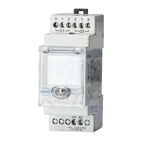
ASTRONOMIC RELAY
ASTRONOMIC PHOTOCELL RELAY
DTR-10/14 which has a real time clock, is an electronic timer that calculate
the sunset and sunrise periods automatically. It designed for controlling
the devices which are connected to it’s contacts according to sunset,
sunrise and the time periods which are proggrammed by the user.
DTR-14 has also a photocell option in addition to above features.
MO
Date
Time
Relay on/off situation
Photocell symbol
(Available only for DTR-14)
ESC button
SET button
ESC button
:
Go to previous menu.
SET button
:
Go to next menu.
DOWN button
:
Scrolling between menus or decrease related value.
Pushing this button 3 seconds on DTR-10’s main menu,
C1 relay position will be changed manually.
Selecting Lock Mode at DTR-14, C1 relay will be on/off on
main menu.
UP button
:
Scrolling between menus or increase related value.
Pushing this button 3 seconds on DTR-10’s main menu,
C2 relay position will be changed manually.
Selecting Lock Mode at DTR-14, C2 relay will be on/off on
main menu.
Safety Precautions
If below precautions are not properly observed and carried out, it can
cause to physical accident or damage to the device and installation.
Disconnect power before working on the device.
When device is connected to the network, do not remove the front panel.
Do not clean the device with solvent or similar items. Only clean with
dried cloth.
Verify correct terminal connections before operate the device.
Connect the device to the electrical panel.
Electrical equipment should be serviced only by your competent seller.
No responsibility is assured by the manufacturer or any of its
subsidiaries for any consequences rising out of the use of this
material.
If the auxiliary supply does not exist, device passes to sleep mode
and display disappears. However, real time clock and related functions
continue to operate. If 4 buttons are pressed at the same time, main menu
displays and so user can see or change all settings.
The loads connected to the C1/C2 relays do not function if auxiliary
supply is off. Even relay status can be mentioned as “on” (
/veya
), but auxiliary supply is a must for the functionality.
There are two reserves in the device. Programmed data is protected
by these reserve against power failure.
For long time reserve, battery CR-2032 is used. The shelf life of this
battery is 5 years, if the device is continously voltage supplied. If the device
is not continously voltage supplied and waited in the shelf, the life of the
battery is 2-3 years (changes according to humidity of the shelf).
For short time, super capacitor is used:
If power fails for 6-10 hours, programmed data is protected by super
capacitor and device continues to its operation. During this time battery
(CR2032) is not used; so battery life extends.
CR-2032 reserve battery should only be changed by authorized service.
In order to use the photocell function, photocell sensor and auxiliary
supply always must be connected.
MANUEL USING :
Using DTR-10’s relay on manuel mode, display must be on main menu.
Pushing DOWN (
) button during 3 seconds C1 relay; pushing UP (
button during 3 seconds C2 relay; After 3 seconds releasing this button
related relays position will change. If relays at ON position it will be OFF,
at OFF position it will be ON. Lock Mode selection does not affect this
application (For details please look at LOCK MODE section).
Using DTR-14’s relay on manuel mode, Lock Mode must be selected. On
main menu Lock sign ( ) must be displayed. Changing C1 relay position
use Down ( ) button, for C2 relay use UP ( ) button.
Note: Push same button for returning previous position of relay.
MENUS :
1 ) PROGRAM (PROG) :
In this menu, program settings can be done. Only one function ON or
OFF can be assigned to each program. Only one of TIME, SUNRISE
or SUNSET functions can be selected (assigned) for this function. The
day and/or days of active can be selected separately for this program.
4 different program assigned in order to make eaiser the using of device
by switch it ON at “sunset” time and switch OFF at “sunrise” time. These
programs which are assigned as default, can be deleted or changed by
the user.
(DTR-10)
Day
TU
WE
TH
FR
SA
SU
00
02
04
06
08
It represents the time
10
12
interval which relays will
14
switch ON.
16
18
20
C1:
C2:
22
24
Lock Mode
UP button
ESC
SET
DOWN button
(Available only for DTR-14)
(DTR-14)
Related steps are mentioned as below:
1.1) Program selection (
User can assign 1 function to any program between P01-P16. Only 1 relay
can be selected via one program and also this relay can only be set as
“switch on” or “switch off”.
For instance; If the status of C1 relay is set as “ON (switch on)”, 1 program
is used.
In order to switch off the relay which was set as “ON” before, another
program must be used (Such as 2nd program).
Star sign which exists after the program number (
the program is assigned.
There are 15 different program choices for DTR-10 (
1.2) Enter / Delete settings (
set a new program or to change the existing program. “
to delete the existing program.
The relay, which is switched on via any program, can not be switched off
by deleting the related program. We can switch off the relay in two ways:
a) Released with manually (for details please look at MANUAL USING
section).
b) Enter the switch off time (OFF) for any relay. Delete the program after
the relay switched it off (OFF).
1.3) C1 / C2 relay selection (
be selected via “P01-C1” or “P01-C2”. 2 different loads can be controlled
with different functions in this way.
1.4) ON/OFF selection (
menu, it is selected that whether selected C1 or C2 relay will switch on or
switch off.
When programmed
relays are programmed as ON. Relay contact position looks like
on the figure at left side. Relay contacts seem at monitor as
or
.
C1, C2
When programmed
relays are programmed as ON. Relay contact position looks like
on the figure at left side. Relay contacts seem at monitor as
or
.
C1, C2
1.5) Function selection (
selection is done in this menu. 1 function can be selected for each program.
4 functions exist: Photo, time, sunset and sunrise.
available only for DTR-14)
1.5.1) (
When photocell sensor perceives the light, (
If lights do not exist, this symbol does not light.
C1 relay can be switched on at all weekdays via photocell function by
using P01 program.
Main Display
SU
SET
SET
00
02
04
06
08
10
12
14
16
18
ve
C1:
C2:
20
22
24
ESC
ESC
As above example, if photocell sensor perceives the darkness, after 10
seconds, photocell symbol ( ) does not light on the main menu and the
relay switches on within 1 minute.
NOTE: Device can only switch on between 12:00 AM and 24:00 PM. Device
can not switch on except this time interval.
C1 relay can be switched off at all weekdays via photocell function by
using P02 program.
Main Display
SU
SET
SET
00
02
04
06
08
10
12
14
16
18
C1:
C2:
20
22
24
ESC
ESC
As above example, if photocell sensor detects the daylight, after 10
seconds, photocell detected symbol ( ) lights on the main menu and the
)
relay switches off within 1 minute.
NOTE: Device only can switch off between 24:00 PM and 12:00 AM. Device
can not switch off except this time interval.
Device can switch on&off once per day via photocell function. Device can
not switch on/off more than once.
1.5.2) (
) Selected relay can be switched on/off at defined
time period.
Main Display
SU
SET
SET
00
02
04
06
08
10
12
14
16
18
C1:
C2:
20
22
24
ESC
ESC
SET
As above example, relay will switch on at 18:00 PM for all weekdays via
time function.
NOTE : Device calculates the sunrise and sunset times automatically
according to the summer/winter time and coordinate information which are
set by user.
1
): Device has 16 different programs.
/
) :
/
): C1 or C2 relay can
/
) / (
or
in program menu, related
or
in program menu, related
/
/
)
) symbol lights.
SET
SET
SET
SET
SET
SET
SET
SET
SET
SET
SET
SET
SET
SET
SET
SET
) represents that
).
is used to
” is used
/
) : In this
/
) : Function
(”PHOTO” function
SET
SET
SET
SET
SET
SET
SET
SET
SET
SET
SET
Advertisement

Related Manuals for Entes DTR-10


Summary of Contents for Entes DTR-10
- Page 1 ASTRONOMIC PHOTOCELL RELAY (DTR-14) Related steps are mentioned as below: DTR-10/14 which has a real time clock, is an electronic timer that calculate 1.1) Program selection ( ): Device has 16 different programs. the sunset and sunrise periods automatically. It designed for controlling User can assign 1 function to any program between P01-P16.
- Page 2 Main Display 9 ) SERVICE MODE ( This mode is valid only for DTR-10 and lets the user control and maintain in urgent situations. In order to choose service mode, lock mode shouldn’t be selected before. In the main menu, up and down buttons (...
- Page 3 ASTRONOMIC RELAY (DTR-10) ASTRONOMIC PHOTOCELL RELAY (DTR-14) DISPLAYS : As above example, C2 relay will switch on for 8 hours. Settings, which are done in the 'menus' section, can be observed in this As the left side example, “08:00” shows the duration section.
- Page 4 ASTRONOMIC RELAY (DTR-10) ASTRONOMIC PHOTOCELL RELAY (DTR-14) Example 1: This relay will switch on via Example 2: This relay will switch on at Wrong application : This relay will switch photocell sensor and will switch off on sunrise time and will switch off at sunset on at sunset timeand will switch off at 02:00 AM.
Need help?
Do you have a question about the DTR-10 and is the answer not in the manual?
Questions and answers