Table of Contents
Advertisement
Quick Links
Advertisement
Table of Contents

Related Manuals for Martinsound Martech Modular Studio Series

Summary of Contents for Martinsound Martech Modular Studio Series
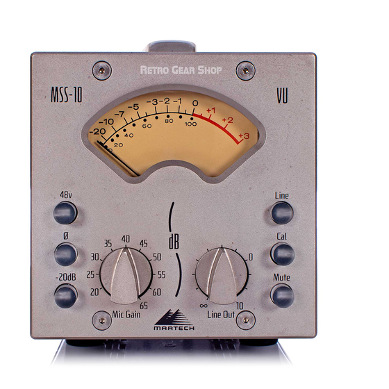
- Page 1 MSS-10 Modular Studio Series Microphone Preamplifier...
- Page 3 MSS-10 Natural Sound Microphone Preamplifier Owner Manual 1151 W. Valley Blvd. Alhambra, CA 91803-2493 800.582.3555 • Phone +1.626.281.3555 • Fax +1.626.284-3092 www.martinsound.com...
- Page 4 Every effort has been made to ensure that the information in this manual is accurate. Martinsound is not responsible for printing or clerical errors. The Martech and Martinsound logos are Trademarks of Martinsound, Inc. Other company and product names mentioned herein are trademarks of their respec- tive companies.
-
Page 5: Table Of Contents
Table of Contents Safety Warnings Introduction Microphone Preamplifier Line Driver To Ground Or Not To Ground? Rear Panel Balanced Impedance Outputs Getting The Most out Of Your MSS-10 Block Diagram Operation Setting Voltage • Changing the Fuse Technical Specifications Design Team A Short History... -
Page 7: Safety Warnings
(service) dans le livret d’instruction accompagnant l’appareil. Copies of the UL and CE Certification Test Reports are on file at Martinsound, Inc. Please contact Martinsound if you have any questions regarding these issues. -
Page 9: Introduction
Introduction Congratulations on the purchase of your MSS-10 Microphone Preamplifier, one of the finest sounding pieces of recording equipment ever developed. This remarkable tool will enable you to make exceptional, natural sounding recordings like never before. Unlike other units, the “watermark” left by your MSS-10 is pure sonic excellence. Its unique lack of coloration or hype will reveal a naturalness that is startling, yet immediately endearing. -
Page 10: Microphone Preamplifier
Microphone Preamplifier Mic Gain Switches the microphone preamplifier gain from 20dB to 65dB in precise 5dB steps using excellent sounding, chemi- cally stabilized, redundant silver switch contacts of the highest quality. This setting determines the output level from the Mic Preamp Out XLR and the level sent to the line driver when Line is not selected. -
Page 11: Line Driver
Line Driver Line Out Adjusts the output level of the line ∞ driver from to +10dB of gain, using a high quality precision potentiometer. Only the Line Out XLR level is affected by the level control. Line Selects the Line In XLR as the line driver source, providing an independent line level path. -
Page 12: To Ground Or Not To Ground
XLRs be connected to chassis (earth), analog ground (0 volts), or floated? Currently the AES is discussing this hot issue and should announce a standard in the near future. Martinsound is paying close attention to these talks in order to easily implement the formalized AES standard(s) into current products. -
Page 13: Rear Panel
Rear Panel Line In Mic Preamp In Bridging Balanced In Transformer Balanced In 10/10 kOhm • Pin 2+, Pin 3– 2.5 kOhm • Pin 2+, Pin 3– Nominal Input: +4dBu Nominal Input: 0 to –65dBu Line Out Mic Preamp Out Single-ended Balanced Impedance Out Single-ended Balanced Impedance Out 50/50 Ohm •... -
Page 14: Balanced Impedance Outputs
Balanced Impedance Outputs Many things were taken into consideration when designing the outputs of the MSS-10 to interface flawlessly with other equipment, with no sonic compromise being the most important. We were faced with three options; a transformer balanced output, an elec- tronically balanced output, or go with a single-ended output. -
Page 15: Getting The Most Out Of Your Mss-10
Getting The Most Out Of Your MSS-10 The Minimalist Approach In this example the MSS-10 is placed in the control room next to the engineer. Mic Preamp In: Connect to the microphone Line Out: Connect to the recorder Line: Deselect to switch the line driver input to the microphone preamplifier Cal: Select to use the VU to set Mic Gain... - Page 16 Mix to Taste! In this example, the MSS-10 is placed in the studio near the microphone or in the control room next to the engineer, and then connected to a console for mixing. The Mic Preamp is selected to feed the line driver, with the Mic Preamp Out con- nected to a console.
- Page 17 Tossing In The Kitchen Sink In this example the MSS-10 is placed in the control room next to the engineer. The Mic Preamp Out is connected to an external process chain, such as an equal- izer and compressor. The process chain output is connected to the balanced Line In of the MSS-10.
-
Page 18: Block Diagram
Block Diagram... -
Page 19: Operation
Operation Attention: XLR connectors are wired according to AES standards • Pin 2 + Inputs are balanced. Outputs are single ended balanced impedance. XLR connectors are wired to AES standards: pin 2 +, pin 3 –, pin 1 chassis. XLR connectors are solder type allowing pin configuration to be changed by a qualified technician if necessary. -
Page 20: Setting Voltage • Changing The Fuse
Selecting Voltage • Changing The Fuse CAUTION: ALWAYS USE AN APPROPRIATELY RATED FUSE FOR THE VOLTAGE SELECTED PRENEZ PRUDENCE: UTILISEZ UN FUSIBLE CORRECTEMENT CLASSÉ POUR LE VOLTAGE SÉLECTIONNÉ TOUJOURS To change the fuse and/or voltage: Turn the power switch off and disconnect the AC cord Pry open the Power Entry Module with a small screwdriver... - Page 21 CAUTION: ALWAYS USE AN APPROPRIATELY RATED FUSE FOR THE VOLTAGE SELECTED PRENEZ PRUDENCE: UTILISEZ UN FUSIBLE CORRECTEMENT CLASSÉ POUR LE VOLTAGE SÉLECTIONNÉ TOUJOURS Remove the fuse on the right side of the Fuse Block Orient the Voltage Select so that the required voltage reads right side up 100 –...
- Page 22 Snap the metal clip onto the left side of the Fuse Block Pay attention to orientation and position of the clip The clip must contact the metal bar (1) and must rest on the plastic bridge just behind the stops (2) Insert the Voltage Select/Fuse Block into the Power Entry Module with the required voltage reading right side up...
-
Page 23: Technical Specifications
Technical Specifications Microphone Preamplifier: Mic Preamp In > Mic Preamp Out Minimum Gain (with Pad) 0 dB Minimum Gain 20 dB Maximum Gain 65 dB Frequency Response 20 dB Gain, 10 Hz to 20 kHz -0.0/+0.5 65 dB Gain, 10 Hz to 20 kHz -0.0/+0.5 Equivalent Input Noise 65 dB Gain, Inputs Shorted... -
Page 24: Design Team
Design Team Modular Studio Series Concept Joe Martinson Shawn Micheal Toby Foster Amplifier Design Bud Wyatt Joe Martinson Transformer Design Toby Foster Joe Martinson Bud Wyatt Sonic Evaluations Shawn Micheal Bud Wyatt Toby Foster Signal Path Layout Shawn Micheal Joe Martinson Schematics &... -
Page 25: A Short History
A Short History... The history of the MSS-10 begins at Martinsound where a passion for excellence in audio has existed since the founding of the company. Martinsound started out as a multi-track recording studio and grew into a highly successful corporation, with divisions that include the development of professional audio products. - Page 26 Well over a year was taken setting up a high resolution listening environment. We knew we would be unable to know when something sounded incorrect if the resolution of the listening system wasn’t high enough. Speakers, power amplifiers, CD players, wire, and A/B switches were auditioned, selected, and modified.
- Page 27 Now we were confident that the MSS-10 microphone preamplifier would astonish even the truly discerning listener. While working on the D2024C, we researched and developed the MARTECH 1005 Input Transformer. Starting with a classic transformer of yesteryear, that was readily accepted in the industry as sounding great, we ripped it apart to see what could be learned.
- Page 28 We Listen. © 2001 Martinsound, Inc.
Need help?
Do you have a question about the Martech Modular Studio Series and is the answer not in the manual?
Questions and answers