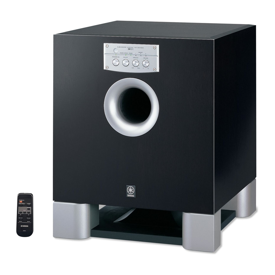
Yamaha YST-SW1500 Owner's Manual
Yamaha subwoofer system owner's manual
Hide thumbs
Also See for YST-SW1500:
- Product catalog (44 pages) ,
- Owner's manual (143 pages) ,
- Service manual (39 pages)
Table of Contents
Advertisement
Quick Links
Advertisement
Table of Contents

Related Manuals for Yamaha YST-SW1500


Summary of Contents for Yamaha YST-SW1500
- Page 1 YST -SW 1 500 Subwoofer System OWNER’S MANUAL...
-
Page 2: Important Safety Instructions
IMPORTANT SAFETY INSTRUCTIONS CAUTION RISK OF ELECTRIC SHOCK DO NOT OPEN CAUTION: TO REDUCE THE RISK OF ELECTRIC SHOCK, DO NOT REMOVE COVER (OR BACK). NO USER-SERVICEABLE PARTS INSIDE. REFER SERVICING TO QUALIFIED SERVICE PERSONNEL. • Explanation of Graphical Symbols The lightning flash with arrowhead symbol, within an equilateral triangle, is intended to alert you to the... - Page 3 This product, when installed as indicated in the instructions contained in this manual, meets FCC requirements. Modifications not expressly approved by Yamaha may void your authority, granted by the FCC, to use the product. IMPORTANT : When connecting this product to accessories and/or another product use only high quality shielded cables.
-
Page 4: Checking The Accessories
CHECKING THE ACCESSORIES Check your package to make sure it contains the following items. G Remote control G Power cable (U.S.A., Canada, Europe and Korean models only) (U.S.A. and Canada models) For U.K. customers If the socket outlets in the home are not suitable for the plug supplied with this appliance, it should be cut off and an appropriate 3 pin plug fitted. -
Page 5: Caution
Thank you for selecting this YAMAHA Subwoofer System. CAUTION: Read this before operating your unit. Please read the following operating precautions before use. YAMAHA will not be held responsible for any damage and/or injury caused by not following the cautions below. ●... -
Page 6: Table Of Contents
Connecting the AC power cable ... 11 FEATURES ● This subwoofer system employs Advanced YAMAHA Active Servo Technology which YAMAHA has developed for reproducing higher quality super-bass sound. (Refer to page 18 for details on Advanced YAMAHA Active Servo Technology.) This super-bass sound adds a more realistic, theater-in- the-home effect to your stereo system. -
Page 7: Placement
PLACEMENT Å ı Ç : subwoofer, : main speaker) One subwoofer will have a good effect on your audio system, however, the use of two subwoofers is recommended to obtain more effect. If using one subwoofer, it is recommended to place it on the outside of either the right or the left main speaker. -
Page 8: Connections
Connecting to line output (pin jack) terminals of the amplifier Connect the main speakers to the speaker output terminals of the amplifier. ● To connect with a YAMAHA DSP amplifier (or AV receiver), connect the SUBWOOFER (or LOW PASS etc.) terminal on the rear of the DSP amplifier (or AV receiver) to the L/MONO INPUT2 terminal of the subwoofer. -
Page 9: Using Two Subwoofers
Using two subwoofers Right main speaker NORMAL H.P.F.OUTPUT /MONO 80Hz 100Hz INPUT INPUT Right subwoofer REMOTE AUTO H.P.F.OUTPUT NORMAL OUTPUT STANDBY TO SPEAKERS /MONO HIGH 80Hz 100Hz OUTPUT INPUT INPUT INPUT FROM AMPLIFIER INPUT POWER AC IN Connecting to the LFE (INPUT3) terminal(s) If your amplifier can cut off high frequencies from the signals for sending to the subwoofer, connect the amplifier to the subwoofer’s LFE (INPUT3) terminal(s). -
Page 10: Connecting To Speaker Output Terminals Of The Amplifier
Connecting to speaker output terminals of the amplifier Using one subwoofer If your amplifier has only one set of main speaker output terminals Connect the speaker output terminals of the amplifier to the INPUT1 terminals of the subwoofer, and connect the OUTPUT terminals of the subwoofer to the main speakers. - Page 11 Using two subwoofers Connect the speaker output terminals of the amplifier to the INPUT1 terminals of the subwoofer, and connect the OUTPUT terminals of the subwoofer to the main speakers. Right main speaker H.P.F.OUTPUT NORMAL /MONO 80Hz 100Hz INPUT INPUT Right subwoofer REMOTE...
-
Page 12: Connecting To H.p.f. Output Terminals
Connecting to H.P.F. OUTPUT terminals The use of the H.P.F. OUTPUT terminals for connections with the amplifier will improve sound quality of your speaker system. The H.P.F. (High-Pass Filter) OUTPUT terminals of the subwoofer cut off frequencies below the selected frequency point from the input signals, and output high frequencies only. - Page 13 To connect two units Right main speaker H.P.F.OUTPUT NORMAL /MONO 80Hz 100Hz INPUT INPUT Right subwoofer AUTO REMOTE H.P.F.OUTPUT NORMAL OUTPUT STANDBY /MONO TO SPEAKERS OUTPUT INPUT HIGH 80Hz 100Hz INPUT INPUT FROM AMPLIFIER INPUT POWER AC IN Switching the H.P.F. OUTPUT switch After the connection is made, select the desired frequency point (80 Hz or 100 Hz) with the H.P.F.
-
Page 14: Ground Connection
If there is a humming noise when using the subwoofer connected to the speaker terminals, connect the subwoofer and the receiver/amplifier with the grounding cable as shown in Illustration A. * If there is no ground terminal (GND) on the receiver/amplifier side, connect the cable to a screw that fastens the top cover of the receiver/amplifier to the rear panel as shown in Illustration B. -
Page 15: Connecting The Ac Power Cable
POWER AC IN (U.S.A. model) POWER AC IN (U.K. model) NOTES ABOUT THE REMOTE CONTROL Battery installation Battery replacement If you find that the remote control must be used closer to the main unit, the batteries are weak. Replace both batteries with new ones. -
Page 16: Controls And Their Functions
CONTROLS AND THEIR FUNCTIONS Rear panel POWER AC IN Remote control Front panel SUBWOOFER SYSTEM YST-SW1500 PRESET MUSIC/MOVIE PHASE STANDBY/ON B.A.S.S. HIGH CUT VOLUME 40Hz 14Hz REMOTE AUTO H.P.F.OUTPUT NORMAL OUTPUT STANDBY TO SPEAKERS /MONO HIGH 80Hz 100Hz OUTPUT INPUT... - Page 17 VOLUME control VOLUME UP/DOWN buttons Adjust the volume level. Turn the control clockwise or press the UP button to increase the volume. Turn the control counterclockwise or press the DOWN button to decrease the volume. To adjust the control on the front panel, put a coin, etc. in the groove on the control and turn it.
-
Page 18: Automatic Power-Switching Function
AUTOMATIC POWER-SWITCHING FUNCTION If the source being played is stopped and the input signal is cut off for 7 to 8 minutes, the subwoofer automatically switches to the standby mode. (When the subwoofer switches to the standby mode by the automatic power- switching function, the power indicator lights up in red.) When you play a source again, the power of the subwoofer turns on automatically by sensing audio signals input to the... -
Page 19: Adjusting The Subwoofer Before Use
Normally, set the control to the level where you can obtain a little more bass effect than when the subwoofer is not used. If the desired response cannot be obtained, adjust the HIGH CUT control and the VOLUME control again. SUBWOOFER SYSTEM YST-SW1500 PRESET MUSIC/MOVIE PHASE STANDBY/ON B.A.S.S. -
Page 20: Storing Preset Data Of The Volume Control Etc
B.A.S.S. HIGH CUT VOLUME 40Hz 14Hz * The default setting of each PRESET button is suitable for using the following Yamaha speaker system with this subwoofer. PRESET 1: NS-8HX, NS-6HX PRESET 2: NS-4HX PRESET 3: NS-2HX Memory back-up The memory back-up circuit prevents the stored data from... -
Page 21: Frequency Characteristics
PHASE–Set to the reverse mode. B.A.S.S.–MOVIE Frequency characteristics 100 dB HIGH CUT 40 Hz HIGH CUT 90 Hz HIGH CUT 140 Hz 100 dB VOLUME Main speaker’s response 100 dB VOLUME Main speaker’s response 500 Hz YST-SW1500 500 Hz YST-SW1500 500 Hz... -
Page 22: Advanced Yamaha Active Servo Technology
ADVANCED YAMAHA ACTIVE SERVO TECHNOLOGY The theory of Yamaha Active Servo Technology has been based upon two major factors, the Helmholtz resonator and negative-impedance drive. Active Servo Processing speakers reproduce the bass frequencies through an “air woofer”, which is a port or opening in the speaker’s cabinet. -
Page 23: Troubleshooting
Refer to the chart below when this unit does not function properly. If the problem you are experiencing is not listed below or if the instructions given below do not help, disconnect the power cable and contact your authorized YAMAHA dealer or service center. -
Page 24: Specifications
YAMAHA ELECTRONICS (UK) LTD. YAMAHA HOUSE, 200 RICKMANSWORTH ROAD WATFORD, HERTS WD1 7JS, ENGLAND YAMAHA SCANDINAVIA A.B. J A WETTERGRENS GATA 1, BOX 30053, 400 43 VÄSTRA FRÖLUNDA, SWEDEN YAMAHA MUSIC AUSTRALIA PTY, LTD. 17-33 MARKET ST., SOUTH MELBOURNE, 3205 VIC., AUSTRALIA Power Consumption ...