Yamaha NS-P430 Owner's Manual
Home cinema 5.1ch speaker package
Hide thumbs
Also See for NS-P430:
- Owner's manual (115 pages) ,
- Service manual (4 pages) ,
- Owner's manual (20 pages)

Related Manuals for Yamaha NS-P430


Summary of Contents for Yamaha NS-P430
- Page 1 NS-P430/ NS-P436 (NS-P430/NS-P436: NX-430P + NX-C430 + YST-SW015) HOME CINEMA 5.1CH SPEAKER PACKAGE/ HOME CINEMA 6.1CH SPEAKER PACKAGE OWNER’S MANUAL...
-
Page 2: Important Safety Instructions
IMPORTANT SAFETY INSTRUCTIONS CAUTION RISK OF ELECTRIC SHOCK DO NOT OPEN CAUTION: TO REDUCE THE RISK OF ELECTRIC SHOCK, DO NOT REMOVE COVER (OR BACK). NO USER-SERVICEABLE PARTS INSIDE. REFER SERVICING TO QUALIFIED SERVICE PERSONNEL. • Explanation of Graphical Symbols The lightning flash with arrowhead symbol, within an equilateral triangle, is intended to alert you to the... - Page 3 This product, when installed as indicated in the instructions contained in this manual, meets FCC requirements. Modifications not expressly approved by Yamaha may void your authority, granted by the FCC, to use the product. IMPORTANT : When connecting this product to accessories and/or another product use only high quality shielded cables.
-
Page 4: Unpacking
Please check to make sure all listed items are included. Speaker cables < > NS-P430 < > NS-P436 Subwoofer cable Fasteners (for NX-C430) HIGH CUT 50–150Hz... -
Page 5: Caution
● Secure placement or installation is the owner’s responsibility. YAMAHA shall not be liable for any accident caused by improper placement or installation of speakers. ● Any time you note distortion, reduce the volume control on your amplifier to a lower setting. -
Page 6: Table Of Contents
COMPONENTS OF THE PACKAGE The speaker package “NS-P430 and NS-P436” is designed for use in a multi-channel audio system such as a home theater system. NS-P430 includes four NX-430P speaker systems, one NX- C430 speaker system and one YST-SW015 subwoofer system. -
Page 7: Setting Up The Speakers
Place the speakers depending on your listening position by following the instructions below. Speaker configuration < > NS-P430 This speaker package employs a 6 speaker configuration: 2 main speakers, 2 rear speakers, a center speaker and a subwoofer. The main speakers emit main source sound. The rear speakers emit surround sounds, and the center speaker emits center sounds (dialog etc.). -
Page 8: Placing The Subwoofer
Placing the subwoofer Å ı : Subwoofer, Placing the center speaker You can place the speaker on top of the TV if the top is flat, on the floor under the TV, or inside the TV rack . Be sure to place the speaker in a stable position. -
Page 9: Mounting The Main/Rear/Center Speakers
Mounting the main/rear/center speakers (and rear center speaker for NS-P436) on the wall Tapping screw (Available at the hardware store) Diam. 3.5 to 4 mm Min. 4 mm 20 mm Wall/ wall support Main/rear/rear center (for NS-P436) 26 mm Center 222.8 mm You can mount the main, rear and/or center speakers (and/ or rear center speaker for NS-P436) on a wall. -
Page 10: Mounting The Main/Rear Speakers (And Rear Center Speaker For Ns-P436) By Using Commercially Available Speaker Stands Or Brackets
(Hole depth : 10 mm) 60 mm Removing the front cover Main/rear/rear center (for NS-P436) Center Using the Yamaha Speaker Stand SPS-10MM (option) By using the Yamaha Speaker Stand SPS-10MM, speakers can be placed on the floor. (Two stands make a set.) SPS-10MM * The SPS-10MM is not available in some areas. -
Page 11: Connections
Caution: Plug in the subwoofer and other audio/video components after all connections are completed. An example of basic connections Amplifier WOOFER OUTPUT INPUT Subwoofer /MONO INPUT AUTO PHASE /MONO STANDBY OFF LOW HIGH NORM REV 110V–120V 220V–240V VOLTAGE SELECTOR POWER To AC outlet CONNECTIONS Main speakers... - Page 12 ● Connect the subwoofer to the line output (pin jack) terminal(s) of the amplifier. * To connect with a YAMAHA DSP amplifier (or AV receiver), connect the SUBWOOFER (or LOW PASS etc.) terminal on the rear of the DSP amplifier (or AV receiver) to the L/MONO INPUT terminal of the subwoofer.
-
Page 13: How To Connect Speaker Cables To The Input And Output Terminals Of The Speakers
How to connect speaker cables to the input terminals of the speakers For connections, keep the speaker cables as short as possible. Do not bundle or roll up the excess part of the cables. If the connections are faulty, no sound will be heard from the speakers. Main speakers Center speaker Use the provided speaker cables (4 m). -
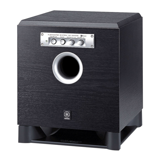
Page 14: Using The Subwoofer (Yst-Sw015)
USING THE SUBWOOFER (YST-SW015) Controls and their functions Front panel Port Rear panel (General model) 110V – 120V 220V – 240V VOLTAGE SELECTOR POWER Power indicator Lights up in green while the subwoofer is on. Lights up in red while the subwoofer is set in the standby mode by the operation of the automatic power- switching function. -
Page 15: Automatic Power-Switching Functon
POWER switch Normally, set this switch to the ON position to use the subwoofer. In this state, you can turn on the subwoofer or turn the subwoofer into the standby mode by pressing the STANDBY/ON ( to the OFF position to completely cut off the subwoofer’s power supply from the AC line. -
Page 16: Adjusting The Subwoofer Before Use
Adjusting the subwoofer before use Before using the subwoofer, adjust the subwoofer to obtain the optimum volume and tone balance between the subwoofer and the main speakers by following the procedures described below. Front panel Rear panel POWER Set the VOLUME control to minimum (0). Turn on the power of all the other components. -
Page 17: Frequency Characteristics
Frequency characteristics Adjustment of the VOLUME control, the HIGH CUT control and the PHASE switch should be changed depending on the room size, the distance from the subwoofer to the main speakers, sources, etc. Following figures show the optimum adjustment of each control and the frequency characteristics when this subwoofer is combined with NX-430P. -
Page 18: Advanced Yamaha Active Servo Technology (For Yst-Sw015)
ADVANCED YAMAHA ACTIVE SERVO TECHNOLOGY (for YST-SW015) The theory of Yamaha Active Servo Technology has been based upon two major factors, the Helmholtz resonator and negative-impedance drive. Active Servo Processing speakers reproduce the bass frequencies through an “air woofer”, which is a port or opening in the speaker’s cabinet. -
Page 19: Troubleshooting
Refer to the chart below when this unit does not function properly. If the problem you are experiencing is not listed below or if the instructions given below do not help, disconnect the power cord and contact your authorized YAMAHA dealer or service center. -
Page 20: Specifications
YAMAHA ELECTRONICS (UK) LTD. YAMAHA HOUSE, 200 RICKMANSWORTH ROAD WATFORD, HERTS WD1 7JS, ENGLAND YAMAHA SCANDINAVIA A.B. J A WETTERGRENS GATA 1, BOX 30053, 400 43 VÄSTRA FRÖLUNDA, SWEDEN YAMAHA MUSIC AUSTRALIA PTY, LTD. 17-33 MARKET ST., SOUTH MELBOURNE, 3205 VIC., AUSTRALIA YST-SW015 Type ...