
Summary of Contents for SD3 ALPHA 2
- Page 1 OPERATING & INSTALLATION Index MANUAL - Rev.2 Date : 30/07/2007 Page : 1/32 ALPHA 2 Rev. 2.1 2 ZONES FIRE DETECTION CONVENTIONAL PANEL...
-
Page 2: Table Of Contents
1-6 OPERATING CHARACTERISTICS OF POWER SUPPLY ......6 1-7 OPTIONAL EN54 FUNCTIONS ..............6 1-8 EXTRA FUNCTIONS ..................6 1-9 DIMENSIONS AND INTERNAL VIEW OF ALPHA 2 ........7 2- INDICATIONS & COMMANDS................. 7 2-1 CONTROL PANEL..................7 2-1-1 A-LED indications of general states of fire panel ......... 8 2-1-2 B-LED indications of faults................ -
Page 3: 1- Fire Detection Panel Alpha 2
The unit is permanently controlled by the electronic of ALPHA 2 which provides a fault condition in case of anomalies like: •... -
Page 4: Technical Specifications
Output voltage of power supply module is out of the admitted limits (< 21V or > 30V) 1-4 TECHNICAL SPECIFICATIONS 1-4-1 General specifications NAME EQUIPMENT ALPHA 2: 2 conventional zones fire detection panel MANUFACTURE CHARACTERISTICS In agreement with EN54-2 and EN54-4 ENVIRONMENT CONDITIONS -5°C ± 3°C... 40°C +/- 2°C, max humidity 93% with no condensation. -
Page 5: Base Module Of Panel
OPERATING & INSTALLATION Index MANUAL - Rev.2 Date : 30/07/2007 Page : 5/32 1-4-3 Base module of panel 2 inputs for bifilar lines supplied with 27V, with line monitoring INPUTS FOR DETECTORS through end of line resistor (see par.8-1) Max 32 detectors or 32 push-buttons with serial limitation resistor TYPE AND NUMBER OF DETECTORS 470Ω¼... -
Page 6: Base Module Consumption
Page : 6/32 1-5 BASE MODULE CONSUMPTION DEVICE: DESCRIPTION: Operating consumption at 24V: Base module in condition of standby with the ALPHA 2 80mA 2 monitored lines connected 1-6 OPERATING CHARACTERISTICS OF POWER SUPPLY PARAMETER OPERATING CONDITIONS MIN UNIT Mains power supply voltage... -
Page 7: Dimensions And Internal View Of Alpha 2
Index MANUAL - Rev.2 Date : 30/07/2007 Page : 7/32 1-9 DIMENSIONS AND INTERNAL VIEW OF ALPHA 2 Measures of panel box ALPHA2: CMP1: H300 x L260 x P125 millimetre. Terminal blocks of ALPHA 2 MODULE detection lines and outputs... -
Page 8: A-Led Indications Of General States Of Fire Panel
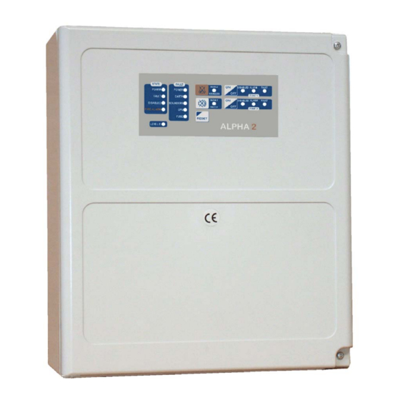
OPERATING & INSTALLATION Index MANUAL - Rev.2 Date : 30/07/2007 Page : 8/32 2-1-1 A - LED indications of general states of fire panel LED POWER Is steady on if the panel is working with the main power source (presence of mains), flashes with a short period of ignition if system lacks mains voltage for less than 20min (working with batteries), it is off if the mains lacks mains voltage for more than 20 minutes (fault) and flashes in normal way if the panel is power supplied by mains... -
Page 9: C-Led Indications And General Commands
OPERATING & INSTALLATION Index MANUAL - Rev.2 Date : 30/07/2007 Page : 9/32 LED FUSE FAULT If on, it indicates that the fault of the fuse places into protection the outputs of panel (sees F3 par.7-1). 2-1-3 C - LED indications and general commands LED DISABLE SOUNDERS If steady on, it indicates that the sounders lines have been deactivated. -
Page 10: 3- Functions & Operations
The activation of access level 2 is obtained by the means of pressing keys (see par.3-3) or can be activated (optionally) also by the means of a setting of jumper on ALPHA 2 module (see JP1 par.7-1). 3- FUNCTIONS & OPERATIONS 3-1 PRE-ALARM, ALARM &... -
Page 11: Enable Access Level 2
: 11/32 3-2 SILENCE BUZZER AND/OR ALARM/FAULT OUTPUTS In case of pre alarm, alarm or fault, ALPHA 2 turns the relative Leds and the buzzer on. The acoustic signal can be deactivated without necessity of advanced access level by pressing for a moment SILENCE BUZZER key. -
Page 12: Autoreset Of First Alarm
(AND of two alarms generates true alarm). If no alarm has occurred within these 3 seconds, ALPHA 2 will cut the power of the relative line for a time corresponding to reset allowing physical reset of detector in alarm. -
Page 13: Enable Configuration
Page : 13/32 4- CONFIGURATION OF PANEL ALPHA 2 is equipped with a non volatile memory on which all the parameters of configuration reside. Some of these parameters can be modified by the installer, in agreement with normative, in order to adapt the panel to the necessities of the installation. -
Page 14: Base Configuration
For the visualization/modification of each parameter, refer to the next pages. 4-2 BASE CONFIGURATION The factory configuration of ALPHA 2 complies with EN 54-2. Before carrying out any modification of the configuration it is necessary to refer first to the standard normative in order to avoid an improper operating setting. - Page 15 If within this time a new alarm occurs on another zone it is registered as a true alarm (AND of two alarms generates true alarm) but if 3 seconds delay has expired ALPHA 2 will apply a reset on detection lines.
-
Page 16: Verify/Modify Configuration Of Delays
In pre alarm conditions the alarm outputs are not activated. If ALPHA 2 has a factory setting (can be modified in par.4-5) the pre alarm will be managed like alarm delayed, it means that after an internal countdown that starts when pre alarm had occurred the pre alarm becomes alarm. - Page 17 OPERATING & INSTALLATION Index MANUAL - Rev.2 Date : 30/07/2007 Page : 17/32 NOTA: It is possible to set aux. outputs as repetition of pre alarm (see par.4-5) Select with the key [SA], [SB] the time you want to be applied (0 to 150 sec.) Led A on: 10 seconds Led B on: 20 second Led C on: 40 seconds...
-
Page 18: Verify/Modify Configuration Of Options
If on, it indicates that a fault condition (except from CPU fault) will activate general pre alarm (If pre alarm mode is set in temporised mode, ALPHA 2 will activate the countdown corresponding to delay of alarm, so that general alarm will be activated by the end of the countdown). - Page 19 OPERATING & INSTALLATION Index MANUAL - Rev.2 Date : 30/07/2007 Page : 19/32 NOTA: It is necessary to choose the option C (factory setting) to comply with EN normative as automatic reset of alarm outputs is prohibited; it is required to reset manually the alarm actuators.
- Page 20 Through keys [SA], [SB] it is possible to enable/disable the following options: Led A Led B Threshold of pre alarm Threshold of alarm End of line resistor Detectors type 21mA 32mA 3,9Kohm ¼ W FARE (SD3) 21mA 36mA 4,7Kohm ¼ W others 12mA 21mA 4,7Kohm ¼ W others Not significant...
-
Page 21: 5- Panel Installation And Mounting
Inside view of ALPHA 2 Legend PART DESCRIPTION Holes for panel wall mounting Holes for screws of frontal closing Connectors for batteries Batteries (not supplied) Hole for cables entrance Module ALPHA 2 Connecting block for the connection of the mains... -
Page 22: Installation
OPERATING & INSTALLATION Index MANUAL - Rev.2 Date : 30/07/2007 Page : 22/32 5-2 INSTALLATION For a proper installation follow these indications: • Identify the better location for panel, detectors and signalization devices • Fix the panel like indicated further •... -
Page 23: 6- Panel Maintenance
3,15AT + BATTERY BLACK BATTERY fig.6 – ALPHA 2 module MCU: Microprocessor of panel. It controls the operation of panel by the means of firmware. The panel configuration resides in the MCU. BZ1: Piezoelectric buzzer for local acoustic signalizations. RL1: Alarm relay. It manages the monitored alarm output (terminal 10 and 11). - Page 24 OPERATING & INSTALLATION Index MANUAL - Rev.2 Date : 30/07/2007 Page : 24/32 RL2: Fault relay SPDT relay , free potential contacts useful to report fault condition. It is normally active and becomes deactivate in fault condition. Maximum applicable I/V load is 1A 30V=. RL3: Battery fault relay .
-
Page 25: Mains Terminal Block (Mr)
OPERATING & INSTALLATION Index MANUAL - Rev.2 Date : 30/07/2007 Page : 25/32 Mains terminal block (MR) L, N Terminal mains input 230V~ +10%/-15% 60Hz. Terminal electrical earth NOTA: the connection of the mains must be executed in conformity with low voltage directives. -
Page 26: Exploitable Outputs (Cn1)
OPERATING & INSTALLATION Index MANUAL - Rev.2 Date : 30/07/2007 Page : 26/32 7-1-3 Exploitable outputs (CN1) Connector CN1 (see fig.6); it makes available the following outputs: Pin: Description: Negative. Positive +27V protected with battery fuse F2 (3,15AT). Output VLINEE. Provides in normal condition +27V with serial 4,7kΩ resistor. That voltage becomes null during cycle of line reset. -
Page 27: Connection Of Alarm Actuators
0,5A. + line 3,9 KΩ ¼ W LED 1A Sounder power supply (27V max 0,5A) 1N4004 type or similar sounder line sounder Polarization LED 1N4004 (or similar) fig.8 - Connection of a generic sounder to panel ALPHA 2... -
Page 28: Connection Of Detectors
OPERATING & INSTALLATION Index MANUAL - Rev.2 Date : 30/07/2007 Page : 28/32 7-3 Connection of detectors The connection of the detectors to the lines/zones is carried out with shielded anti flame cables, 2 x 0,5mm² min, with shield connected to earth of panel. 32 detectors or push-buttons max (470 Ω... -
Page 29: 8- Connection Diagram
: 30/07/05 Page : 29/32 8- Connection diagram 8-1 Connection of detectors FARE (SD3) OC05/TRC05/TSC05 to panel 32 conventional detectors max [OC05/TRC05/TSC05], with 3,9KΩ ¼ W NOTA: for a correct operation make sure that Fare thresholds (factory end of line resistor (orange-white-red-gold) setting) are set (see par.4-5) -
Page 30: Connection Of Visual/Acoustic Indicators To Panel
Concerning the 2 wire connection of P7264/P7265 (powered), leave open the terminal block 3 and close the jumper JP2 on position B. For 2 wire connection of P7266/P7268 (self-powered) leave open terminal block 3 and close jumper JP2 on position A (see specific documentation). Figure 10- Connection of sounders to ALPHA 2 panel... - Page 31 FAST GUIDE These pages resume the main functions of panel. It is therefore advised to detach this section and to conserve it close to panel. The table refers to the following figure. Figure 11 – ALPHA 2 panel DESCRIPTION POWER (1) ON indicates the panel is working with the main power source (presence of mains).
- Page 32 OPERATING & INSTALLATION Index Date : 30/07/05 MANUAL Page : 32/32 NOTA: The regular blinking of a led indicates the memorization of an event that is no longer present. DESCRIPTION OF THE KEY COMMANDS: ENABLE/DISABLE ZONES (P1, P2) Access level 1: allows to access level 2. Access level 2: enabling/disabling zones.
Need help?
Do you have a question about the ALPHA 2 and is the answer not in the manual?
Questions and answers