
Related Manuals for Hafco WoodMaster PJ-6B


Summary of Contents for Hafco WoodMaster PJ-6B
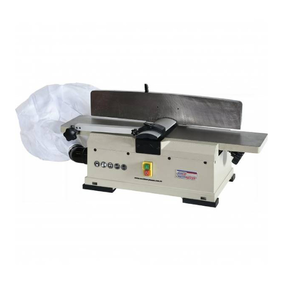
- Page 1 Operator’s Manual 10-9-2020 PJ-6B BENCH PLANER JOINTER (#W618) CAUTION: Read and follow all Safety Rules and operating Instructions before First Use of this Product. Keep this manual with tool.
-
Page 2: Product Specifications
PRODUCT SPECIFICATIONS Jointer / Planer Motor 240V 50Hz 1100W Max Cutting Width 153mm Max Cutting deep Cuts Per Minute 20000 Table Size 730X160mm Fence Size 580X110mm Dust collection port 60.5mm Fence angle -45° to +45° SAFETY INSTRUCTIONS WARNING: When using electric tools, basic safety precautions, including the following, should always be followed to reduce the risk of fire, electric shock and personal injury. - Page 3 footwear are recommended when working outdoors. Wear protecting hair covering to contain long hair. 11. Use safety glasses and hearing protection. Also use face or dust mask if the cutting operation is dusty. 12. Do not abuse the cord. Never carry the tool by the cord of yank it to disconnect it from the socket, Keep the cord away from heat, oil and sharp edges.
-
Page 4: Electrical Requirements
ADDITIONAL SATETY RULES FOR THIS PRODUCT 1. Be alert and think clearly. Never operate power tools when tired, intoxicated or when taking medications that cause drowsiness. 2. Keep hands away from moving parts and cutting surfaces. 3. Feed work into blade or cutter against the direction of rotation. 4. -
Page 5: Guidelines For Extension Cords
Properly Ground Outlet Grounding Prong 3-Prong Plug WARNING: Improper connection of equipment grounding conductor can result in the risk of electrical shock. equipment should be grounded while in use to protect operator from electrical shock. -Check with a qualified electrician if you do not understand grounding instructions or if you are in doubt as to whether the tool is properly grounded. -
Page 6: Carton Contents
CARTON CONTENTS UNPACKING AND CHECKING CONTENTS Carefully unpack the machine and all its parts, and compare against the illustration following. WARNING: ⚫ To avoid injury from unexpected starting, do not plug the power cord into a power source receptacle during unpacking and assembly. - Page 7 ASSEMBLY ## Caution. Keep away from Sharp spindle blades ## ATTACH SUPPORT TO PLANER• ⚫ Remove the two socket head screws and washers from the planer, attach fence support to planer using the screws and washers. ⚫ Insert locking plate into support. Holding the locking plate and assemble the fence sliding handle and spacer.
- Page 8 ⚫ Make sure limit plate is resting in slot of block. Position fence against shaft and lock fence in position with fence tilting handle. ⚫ Place a combination square against face of fence and table surface. The fence and table must be at 90°...
- Page 9 INSTALL THE DUST CHUTE Slide dust chute onto end of chip exhaust. Tighten pan head screw. Dust chute INSTALLING THE FILTER BAG Open the zipper on the bottom of the bag, place the spring inside of the filter bag arm. Slide the spring &...
- Page 10 Turning the handwheel clockwise will raise the infeed table causing less wood to be removed from workpiece. Do not make jointing or planing cuts deeper than 3mm. Infeed table Handwheel POSITION THE FENCE The fence can be position positioned to plain the wood at any angle from 45°inward to 45°outward. Before adjusting the fence position, make sure the power is turn off.
- Page 11 as high as the out feed table when positioned at the highest point. To check blade height: ⚫ Loosen the bridge cover locking knob, pull out the bridge cover. ⚫ Turn the cutter head so that one of the blades is at the highest position. CAUTION: The cutter head blades are extremely sharp.
- Page 12 the grain take very light cuts and feed slowly. When using long work pieces use extra supports at both end of the planer. Tighten the knob For your safety, use the push block or push stick to hold and feed workpiece when jointing wood that is narrower than 75mm (3″), planing wood thinner than 75mm (3″).
-
Page 13: Maintenance
BEVELING AND DHAMFERING ⚫ The fence on the jointer/planer is adjustable from45° inward to 45° outward. Adjust the fence to the desired angle and tighten fence tilting handle. ⚫ Beveling refers to cutting the entire edge of a board at an angle. Beveling may require several passes due to the depth of cut needed. -
Page 14: Troubleshooting
blade clamp using the four blade lock screws, do not tighten the blade lock screws until you have checked the blade height ,adjust as required using straight edge as described in “adjusting blade height”. Tighten blade lock screws, recheck blade adjustment and make sure blade is still level with out feed table. Repeat procedure to replace the other blade, remove the scrap wood release blade guard. -
Page 15: Exploded View
EXPLODED VIEW... -
Page 16: Parts List
PARTS LIST Description QTY. Description QTY. Hex nut Hex nut Block Set screw Shaft Hex nut Spring Support plate Limit plate Lock washer Socket head screw Socket head screw Fence bracket Elevation screw Hex nut Handwheel Bracket shaft Flat washer Socket head screw Pan head screw Push nut... - Page 17 Description QTY. Description QTY. Pan head screw Fan shaft Ball bearing Drive belt Spacer Shaft Set screw Screw Fan pulley Blade clamp Thread forming screw Blade Base Cutter head Switch Jack screw Flat head screw Set screw Cover Set screw Flat washer Drive pulley Pan head screw...
Need help?
Do you have a question about the WoodMaster PJ-6B and is the answer not in the manual?
Questions and answers