Table of Contents
Advertisement
Quick Links
TRANSLATION OF THE ORIGINAL OPERATING INSTRUCTIONS
IMPORTANT
READ CAREFULLY BEFORE USE
KEEP SAFE TO CONSULT AT A LATER DATE
1
Operating instructions for HERCULES BROSE Topology MY21
PASERO COMP I-12, PASERO COMP I-F5, PASERO PRO I-12, PASERO SPORT I-10, PASERO SUV I-10
21-Q-0023, 21-Q-0024, 21-Q-0025, 21-Q-0026, 21-Q-0027, 21-Q-0028, 21-Q-0029, 21-Q-0030, 21-Q-0031, 21-Q-0032, 21-Q-0033, 21-Q-0079, 21-Q-0080
MY21H02 - 12 • 1.0 • 19. October 2020
Advertisement
Table of Contents

Related Manuals for Hercules PASERO COMP I-12


Summary of Contents for Hercules PASERO COMP I-12
- Page 1 KEEP SAFE TO CONSULT AT A LATER DATE Operating instructions for HERCULES BROSE Topology MY21 PASERO COMP I-12, PASERO COMP I-F5, PASERO PRO I-12, PASERO SPORT I-10, PASERO SUV I-10 21-Q-0023, 21-Q-0024, 21-Q-0025, 21-Q-0026, 21-Q-0027, 21-Q-0028, 21-Q-0029, 21-Q-0030, 21-Q-0031, 21-Q-0032, 21-Q-0033, 21-Q-0079, 21-Q-0080...
-
Page 2: Table Of Contents
Contents Contents About these operating instructions 3.1.3 Brake system Manufacturer 3.1.3.1 Disc brake Language 3.1.4 Electric drive system Laws, standards and directives 3.1.4.1 Motor For your information 3.1.4.2 Rechargeable battery 1.4.1 Warnings 3.1.5 On-board computer 1.4.2 Markups 3.1.5.1 Operating element Nameplate Proper use Type number and model... - Page 3 Contents Commissioning 6.12 Rechargeable battery Preparing the battery 6.12.1 Removing the battery 5.4.1 Checking the battery 6.12.2 Inserting the battery 5.4.2 Retrofitting the battery locking lever 6.12.3 Charging the battery 5.4.2.1 Preparing the frame 6.12.4 Waking the battery 5.4.2.2 Fitting the locking lever 6.13 Electric drive system 5.4.3...
- Page 4 11.1 Parts list 7.4.1.3 Checking and adjusting the tyre 11.1.1 PASERO PRO I-12 pressure – Dunlop valve 11.1.2 PASERO COMP I-12 7.4.1.4 Checking and adjusting the tyre 11.1.3 PASERO COMP I-F5 pressure – Presta valve 11.1.4 PASERO SPORT I-10 7.4.1.5 Checking and adjusting the tyre 11.1.5...
- Page 5 About these operating instructions Thank you for your trust! Copyright © HERCULES GmbH HERCULES pedelecs are premium quality bicycles. You have made an excellent choice. Distribution or reproduction of these operating Your specialist dealer will provide you with instructions and utilisation or communication of...
-
Page 6: About These Operating Instructions
Manufacturer 1.4.1 Warnings The pedelec manufacturer is: Warnings indicate hazardous situations and HERCULES GMBH actions. You will find warnings in the operating Longericher Straße 2 instructions: 50739 Köln, Germany Tel.: +49 4471 18735 0... -
Page 7: Markups
About these operating instructions 1.4.2 Markups Instructions for specialist dealers are highlighted in grey. They are indicated by a screwdriver symbol. Information for specialist dealers does not require non-professionals to take any action. You will find stylised forms of typeface in the operating instructions: Stylised form Italics... -
Page 8: Nameplate
Nameplate The nameplate is situated on the frame. You can You will find thirteen pieces of information on the see the exact position of the nameplate in Figure 2. nameplate. Hercules GmbH Longericher Str. 2 50739 Köln, Germany Typ: 21-17-1017... -
Page 9: Type Number And Model
PASERO PRO I-12 City and trekking (Trapez) bicycle 21-Q-0025 PASERO PRO I-12 City and trekking (central tube) bicycle 21-Q-0026 PASERO COMP I-12 City and trekking (Diamant) bicycle 21-Q-0027 PASERO COMP I-12 City and trekking (Trapez) bicycle 21-Q-0028 PASERO COMP I-12... -
Page 10: Safety
Safety Safety Residual risks 2.1.1 Risk of fire and explosion 2.1.1.2 Overheated charger The charger heats up when charging the battery. 2.1.1.1 Rechargeable battery In case of insufficient cooling, this can result in fire The safety electronics may fail if the batteries are or burns to the hands. -
Page 11: Risk Of A Crash
Safety 2.1.3 Risk of a crash Toxic substances 2.2.1 Brake fluid 2.1.3.1 Incorrect quick release setting Brake fluid may leak out after an accident or due Excessively high clamping force will damage the to material fatigue. Brake fluid can be fatal if quick release and cause it to lose its function. -
Page 12: Personal Protective Equipment
Safety Personal protective equipment What to do in an emergency Wear a suitable cycling helmet, sturdy footwear 2.7.1 Dangerous situation in road traffic and typical close-fitting clothing to provide In the event of any hazards or dangers in road protection. -
Page 13: Battery Vapours Emitted
Safety 2.7.4 Battery fire Environmental protection measures Never allow brake fluid to flow into the sewage The safety electronics may fail if the battery is system, water courses or groundwater. damaged or faulty. The residual voltage can cause a short circuit. The battery may self-ignite ... -
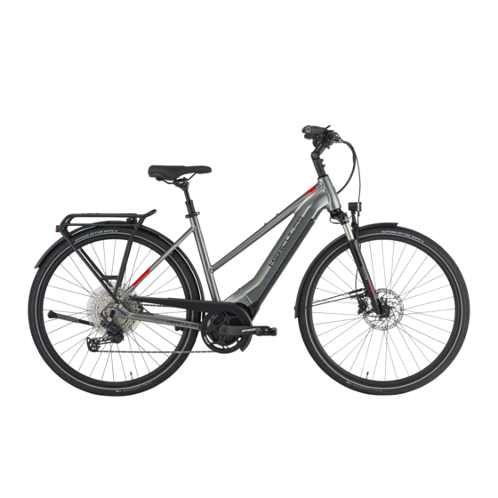
Page 14: Overview
Overview Overview 14 15 16 Figure 2: Pedelec on right, Pasero Front wheel Rear light and reflector Fork Rear mudguard Front mudguard Kickstand Headlight Chain Handlebars Rear wheel Stem Chain guard Frame Battery with nameplate Seat post Frame number Saddle Pannier rack MY21H02 - 12_1.0_19.10.2020... -
Page 15: Description
Overview Description 3.1.2.2 Suspension fork A suspension fork is based either on a steel spring or 3.1.1 Wheel air suspension. Unlike a rigid fork, a suspension fork has two functions which improve floor contact and comfort: suspension and damping. The suspension prevents an impact, such as one caused by a stone lying in the pedelec's path, from being channelled directly into the rider's body via the fork. - Page 16 Overview Negative deflection with the ground when passing over bumps (blue line). The negative deflection (sag) is the percentage of total deflection that is compressed by the rider's The fork head, handlebars and rider broadly follow weight, including equipment (such as a the terrain (green line) when riding over bumps.
-
Page 17: Steel Suspension Fork
Overview 3.1.2.3 Steel suspension fork 3.1.2.4 Air suspension fork The stem and handlebars are fastened to the fork The air suspension fork features an air suspension assembly (orange), a compression damper steerer. The wheel is fastened to the axle. assembly (blue) and, in some cases, a rebound damper assembly (red). -
Page 18: Brake System
Overview 3.1.3 Brake system Every pedelec has a hydraulic brake system. The brake fluid is in a closed hose system. If the rider pushes the brake lever, the brake fluid activates the brake on the wheel. The mechanical brakes are used as an emergency stop system and bring the bicycle to a halt quickly and safely in the event of an emergency. -
Page 19: Electric Drive System
Overview 3.1.4 Electric drive system Headlight On-board computer/operating element The pedelec is driven by muscle power applied to Rechargeable battery the chain drive. The force which is applied by Rear light pedalling in the direction of travel drives the front Motor chain wheel. -
Page 20: On-Board Computer
Overview The pedelec has an integrated battery. 3.1.5.1 Operating element The control panel on the handlebars uses four buttons to control the on-board computer. Figure 13: Details of SuperCore rechargeable battery Handle lever On/off switch Battery level indicator Figure 15: Operating element overview Charging and discharging socket On/off switch Label on the rear... -
Page 21: Proper Use
Overview Proper use The pedelec must only be used in perfect, fully actions in these operating instructions met. functional condition. National requirements may Approved accessories can be installed by apply to the pedelec which the standard specialist staff. equipment may not meet. For riding on public The rechargeable batteries are designed to roads, some special regulations apply in relation supply power to the pedelec motor only and must... -
Page 22: Improper Use
Overview Improper use Failure to adhere to the proper use poses a risk of • lending the pedelec to untrained riders • carrying other people personal injury and material damage. It is • riding with excessive baggage prohibited to use the pedelec in the following •... -
Page 23: Maximum Permitted Total Weight
21-Q-0023 PASERO PRO I-12 135 kg 21-Q-0024 PASERO PRO I-12 135 kg 21-Q-0025 PASERO PRO I-12 135 kg 21-Q-0026 PASERO COMP I-12 135 kg 21-Q-0027 PASERO COMP I-12 135 kg 21-Q-0028 PASERO COMP I-12 135 kg 21-Q-0029 PASERO COMP I-F5... -
Page 24: Technical Data
Overview Technical data 3.4.1 Pedelec 3.4.4 Brose Topology on-board computer Transportation temperature 5 °C - 25 °C Power supply DC 24V/36V/48V Ideal transportation temperature 10 °C - 15 °C Rated current 30 ma/36 V Storage temperature 5 °C - 25 °C Switch-off point in the event of <1uA residual current... -
Page 25: Supercore 555 Battery
Overview 3.4.6 SuperCore 555 battery Nominal capacity 15 Ah Energy 555 W Maximum discharging current, 25 A continuous Maximum charging current, continuous 5 A Voltage 36 V Maximum charging voltage 42 V Weight 3.3 kg Dimensions in mm (W × H × L) 130 ×... -
Page 26: Description Of Controls And Screens
Overview Description of controls and 1 Level of assistance indicator screens The higher a level of assistance, the more the drive system assists the rider when pedalling. The 3.5.1 Handlebars following levels of assistance are available. Symbol Designation Area of use Riding without motor assistance Low assistance for maximum battery life. -
Page 27: Set Screen
Overview 6 Battery level indicator (on-board computer) 9 Motor power indicator The battery level indicator consists of 5 segments. The motor power is displayed using six bars If the battery level is less than 5 %, the battery Charging icon turns yellow and starts to flash. The battery level indicator starts flashing. -
Page 28: Daytime And Night Mode
Overview 3.5.3 Battery level indicator (rechargeable To see the system settings, the rider needs to battery) access the system settings. The rider can change the values of the system settings. The battery indicator is on the battery: Designation Function BA CK CO L O R Setting background colour U NI T Setting units... -
Page 29: Environmental Requirements
Overview Environmental requirements You can be ride the pedelec within a temperature Temperatures under -10 °C and over +40 °C must range between 5 °C and 35 °C. The electric drive be avoided. system is limited in its performance outside this You must also keep within the following temperature range. - Page 30 Overview The pedelec is unsuitable for the following areas of use: Child's bicycles/ City and trekking Area of use bicycles for young Mountain bikes Racing bicycle Cargo bike Folding bicycle bicycles adults Never drive off-road Never drive off-road Never drive off-road Never drive off-road Never drive off-road or perform jumps.
-
Page 31: Transportation And Storing
Transporting and storing Transportation and storing Physical transport characteristics Weight and dimensions during transportation 53 cm t.b.a. t.b.a. t.b.a. 21-Q-0032 57 cm t.b.a. t.b.a. t.b.a. 61 cm t.b.a. t.b.a. t.b.a. 53 cm t.b.a. t.b.a. t.b.a. 53 cm t.b.a. t.b.a. t.b.a. 21-Q-0033 57 cm t.b.a. -
Page 32: Transportation
Transporting and storing Transportation 4.3.2 Transporting the pedelec Bicycle racks which use the handlebars or frame CAUTION to hold the pedelec in an upside-down position exert inadmissible forces on its components Crash caused by unintentional activation during transportation. This can cause the There is a risk of injury if the drive system is supporting parts to break. -
Page 33: Storing
Transporting and storing Storing 4.4.2 Break in operation Notice CAUTION The battery discharges when not in use. This can Accident after storage cause irreparable damage to the battery. The battery must be recharged every The brake system is not designed for use on a 6 months. -
Page 34: Assembly
Assembly Assembly Unpacking WARNING The packaging material consists mainly of cardboard and plastic film. Risk of eye injury Problems may arise if the settings are not made The packaging has to be disposed of in to components correctly and you may sustain accordance with the regulations of the serious injuries as a result. -
Page 35: Preparing The Battery
Assembly Experience has shown that a pedelec which has 5.4.2.1 Preparing the frame not yet been sold is automatically handed to 1 Cut out the drilling template in Section 11.4 customers as soon as it appears ready to ride. along the blue dotted line. ... -
Page 36: Fitting The Locking Lever
Assembly 5.4.3 Installing the wheel in the Suntour 5.4.2.2 Fitting the locking lever fork 1 Insert the countersunk screws (1) into the base plate (2). 1 Before installing, ensure that the quick release flange is extended. Open the lever fully. Figure 26: Inserting countersunk screws into base plate Figure 29: Open and closed flange 2 Join the locking lever to the base plate using... -
Page 37: Checking The Stem And Handlebars
Assembly 4 Fully close the quick release. Check that the 5.4.4.3 Checking the headset backlash quick release is firmly in place and adjust it on 1 To check the handlebar headset backlash, the flange if necessary. close the quick release lever on the stem. ... -
Page 38: Operation
Operation Operation Risks and hazards CAUTION WARNING Crash caused by loose clothing Injuries and death caused by other road users Shoe laces, scarves and other loose items may become entangled in the spokes on the wheels Other road users, trucks, cars or pedestrians often and on the chain drive. -
Page 39: Personal Protective Equipment
Operation Notice CAUTION Moisture penetrating at low temperatures may Crash caused by poor road conditions impair individual functions due to the open structural design. Loose objects, such as branches and twigs, may become caught in the wheels and cause a crash ... -
Page 40: Tips For A Greater Range
Operation Tips for a greater range The pedelec's range depends on many Tyres influencing factors. A single battery charge may Always select the right tyres for the surface only last fewer than 20 kilometres but much more type. than 100 is also possible. There are a few tips ... -
Page 41: Error Messages
Operation Error messages 6.4.1 Error message display Parts of the electronic drive system are Code Description Method of resolution permanently monitored during use and charging. If an error is detected, the error code detected The measured current Reduce the load on the exceeds the maximum motor by pedalling less or appears on the display screen. - Page 42 Operation Code Description Method of resolution Code Description Method of resolution The difference in Re-start the system. Error detected in the Re-start the system. torque between two program start-up. Contact your specialist Contact your specialist measurements exceeds the permitted dealer if the problem dealer if the problem value (±...
-
Page 43: Instruction And Customer Service
Operation Instruction and customer service Adjust the saddle tilt to horizontal. Your supplying specialist dealer will provide customer service. Contact details can be found on the pedelec pass for these operating instructions. The specialist dealer will explain all the pedelec functions to you in person, this being when the specialist dealer hands over the pedelec at the latest. -
Page 44: Adjusting The Seat Height With Quick
Operation 6.6.1.3 Adjusting the seat height with quick 6.6.1.4 Adjusting the seat position release The saddle can be shifted on the saddle frame. 1 Open the quick release on the seat post to The right horizontal position ensures an optimal change the seat height (1). -
Page 45: Adjusting The Handlebars
Operation 6.6.2 Adjusting the handlebars CAUTION Crash caused by incorrectly set clamping force Excessively high clamping force will damage the quick release and cause it to lose its function. Insufficient clamping force will result in unfavourable transmission of force. This can cause components to break. -
Page 46: Retracting The Brake Linings
Operation 6.6.4.1 Retracting the brake linings Greater sag (20% to 30%) Disc brakes require wearing-in time. The braking A greater sag increases sensitivity to bumps, thus force increases over time. You therefore need to be producing greater suspension motion. A greater aware that the braking force may increase during the sensitivity to bumps ensures more comfortable wearing-in period. -
Page 47: Adjusting The Suntour Fork Air
Operation Turn the sag setting wheel clockwise to 3 Detach high-pressure damper pump. increase the spring pre-tensioning. 4 Measure the distance between the crown and Turn the sag setting wheel anti-clockwise to the dust seal. This distance is total deflection of decrease the spring pre-tensioning. -
Page 48: Adjusting The Rebound Damping
Operation 6.6.6 Adjusting the rebound damping Rebound damping in the suspension fork and the If the air pressure or spring stiffness increases, rear frame damper determines the speed at which the extension and rebound speeds also increase. the rear frame damper rebounds after being Rebound damping may need to be increased to subjected to load. -
Page 49: Adjusting The Suntour Air Suspension
Operation 6.6.6.1 Adjusting the Suntour air suspension fork Only applies to pedelecs with this equipment 1 Turn the Suntour rebound screw in a clockwise direction to the closed position until it stops. Figure 43: Suntour rebound screw (2), fork (1) 2 Turn the Suntour rebound screw slightly in an anti-clockwise direction. -
Page 50: Accessories
Operation Accessories CAUTION We recommend a parking stand into which either Risk of crushing due to exposed springs the front wheel or rear wheel can be inserted securely for pedelecs which do not have a The child may crush his/her fingers on exposed kickstand. -
Page 51: Trailer
Operation 6.7.2 Trailer 6.7.2.1 Trailer approval for Enviolo hub gear Only compatible bicycle trailers are approved for CAUTION Enviolo hub gears. Crash caused by brake failure KETTLER The braking distance may be longer if the trailer KETTLER Quadriga child trailer is carrying excessive load. -
Page 52: Pannier Rack
Operation 6.7.3 Pannier rack 6.7.6 Tubeless and airless The specialist dealer will advise on choosing a Riding a bike without tyre tubes reduces the risk suitable pannier rack. of tyre punctures and even avoids them completely. The specialist dealer must install the pannier rack the first time to ensure that it is safely fitted. -
Page 53: Check List Before Each Ride
Operation Check list before each ride Check the pedelec before each ride. Take the pedelec out of service if you spot any anomalies. Check that the pedelec is complete. Check the battery is firmly in place. Check that the lighting, reflector and brake, for instance, ... -
Page 54: Raising The Kickstand
Operation Raising the kickstand Distribute the baggage as evenly as possible between the left- and right-hand side. Use your foot to raise the kickstand completely We recommend the use of panniers and before setting off. baggage baskets. 6.10 Using the pannier rack The maximum load bearing capacity is indicated... -
Page 55: Rechargeable Battery
Operation 6.12 Rechargeable battery 6.12.2 Inserting the battery 1 Place the battery into the lower mount with the Switch off the battery and the drive system before contacts facing the front. removing or inserting the battery. 2 Open the lock with the key. 6.12.1 Removing the battery 3 Press the key towards the down tube and hold. -
Page 56: Charging The Battery
Operation 6.12.3 Charging the battery When the drive system is switched on, the display screen shows the charging process. If an error occurs during the charging process, a system message is displayed. Remove the Symbol Charging charger and battery from operation immediately and follow the instructions. -
Page 57: Electric Drive System
Operation 6.13 Electric drive system 6.13.1 Switching on the electric drive system CAUTION Crash caused by lack of readiness for braking When it is switched on, the drive system can be activated by the application of force on the pedals. There is a risk of a crash if the drive is activated unintentionally and the brake is not reached. -
Page 58: On-Board Computer
Operation 6.14 On-board computer 2 Press the function button briefly. 3 Press the up button or down button briefly to enter the PIN. Notice Never use the on-board computer as a handle. The initial PIN is 0000. The on-board computer may become irreparably damaged if you use it to lift the 4 Press the function button briefly. -
Page 59: Using The Push Assist System
Operation 6.14.4 Using the push assist system CAUTION Injury from pedals or wheels The pedals and the drive wheel turn when the push assist system is used. There is a risk of injury if the pedelec wheels are not in contact with the ground when the push assist system is used (e.g. -
Page 60: Switching The Journey Information
Operation 6.14.6 Switching the journey information The rider can change the values of the system settings. Press the function button briefly. Designation Function The function display shows three different items of BA CK CO L O R Setting background colour journey information one after the other: U NI T Changing the units... -
Page 61: Setting Units
Operation 6.14.7.2 Setting units 6.14.7.4 Setting the clock 1 Press the U N I T menu sub-item on the 1 Press C L O C K menu sub-item on the <Set screen>. <Set screen>. Figure 53: <UNIT indicator> 2 Press the up button or down button briefly to select km/h (kilometres per hour) or MPH (miles per hour). -
Page 62: Switching The Pin Prompt On And Off
Operation 6.14.7.5 Switching the PIN prompt on and off 6.14.7.6 Changing the PIN 1 Press the S ET P A S SW O R D menu sub-item The PIN prompt is switched on. on the <Set screen>. 1 Press the S ET P A S SW O R D menu sub-item on the <Set screen>. -
Page 63: Resetting The Settings
Operation 6.14.7.7 Resetting the settings Press R E S E T menu sub-item on the <Set screen>. Figure 58: <RESET screen> Press the up button or down button briefly to select YE S . Press the function button briefly. ... -
Page 64: Brake
Operation 6.15 Brake 6.15.1 Using the brake lever WARNING Crash caused by brake failure If the brakes are applied continuously for a long time (e.g. while riding downhill for a long time), the fluid in the brake system may heat up. This may create a vapour bubble. -
Page 65: Suspension And Damping
Operation 6.16 Suspension and damping 6.16.1 Suspension fork compression adjuster The compression adjuster makes it possible to during transitions, cornering, uniform impacts make quick adjustments to the fork’s suspension caused by bumps and when braking. behaviour to adapt to changes in terrain. It is When optimally adjusted, the fork counteracts intended for adjustments made during the ride. -
Page 66: Adjusting The Suntour Compression Adjuster
Operation The threshold setting can be used to improve pedalling efficiency over flat, hilly, level or slightly rugged terrain. In threshold mode, higher pedelec speeds lead to greater impact force when a pedelec hits a bump, causing the fork to deflect, and the bump is absorbed. -
Page 67: Gear Shift
Operation 6.17 Gear shift The selection of the appropriate gear is a prerequisite for a physically comfortable ride and making sure that the electric drive system functions properly. The ideal pedalling frequency is between 70 and 80 revolutions per minute. ... -
Page 68: Parking The Pedelec
Operation 6.18 Parking the pedelec Notice Heat or direct sunlight can cause the tyre pressure to increase above the permitted maximum pressure. This can destroy the tyres. Never park the pedelec in the sun. On hot days, regularly check the tyre pressure and adjust it as necessary. -
Page 69: Cleaning And Servicing
Cleaning and servicing Cleaning and servicing Cleaning after each ride Required tools and cleaning agents: Cleaning check list • Cloth Clean the pedals after each ride • Air pump • Brush Clean the suspension fork and, if after each ride •... -
Page 70: Basic Cleaning
Cleaning and servicing Basic cleaning 7.2.1 Cleaning the frame 1 Soak the entire frame with dish-washing CAUTION detergent if the dirt is thick and ingrained. 2 After leaving it to soak for a short time, remove Crash caused by brake failure the dirt and mud with a sponge, brush and The braking effect may be unusually poor toothbrushes. -
Page 71: Cleaning The Chain
Cleaning and servicing 7.2.6 Cleaning the chain 7.2.8 Cleaning the on-board computer Notice Notice Never use aggressive (acid-based) cleaners, If water enters the on-board computer, it will be rust removers or degreasers when cleaning permanently damaged. the chain. Never immerse the on-board computer in ... -
Page 72: Cleaning The Brake
Cleaning and servicing 7.3.1 Servicing the frame 7.2.10 Cleaning the brake Dry the frame. WARNING Spray with care oil. Brake failure due to water penetration Clean off the care oil again after a short time. The brake seals are unable to withstand high 7.3.2 Servicing the stem pressures. -
Page 73: Maintenance
Cleaning and servicing Maintenance 7.4.1.1 Checking the tyres Check the tyre wear. The tyre is worn if the CAUTION anti-puncture protection or the carcass cords are visible. Crash and falling caused by unintentional A specialist dealer will need to change the tyre activation if it is worn. -
Page 74: Checking And Adjusting The Tyre
Cleaning and servicing 7.4.1.4 Checking and adjusting the tyre 7.4.2 Brake system pressure – Presta valve CAUTION Only applies to pedelecs with this equipment It is recommendable to use Crash caused by brake failure a bicycle pump with a pressure gauge. -
Page 75: Checking The Electrical Cables And Brake Cables
Cleaning and servicing 7.4.6 Checking the electrical cables and 7.4.9 Checking the belt and chain tension brake cables Notice Check all visible electrical cables and Bowden Excessive chain tension increases wear. cables for damage. If the sheathing is compressed, a brake is defective or a light If the chain tension is too low, there is a risk that does not work, the pedelec must be removed the chain or the drive belt will slip off the chain... -
Page 76: Maintenance
Maintenance Maintenance CAUTION Hazard for the environment due to toxic WARNING substances Injury due to damaged brakes The brake system contains toxic and Special tools and specialist knowledge are environmentally harmful oils and lubricants. Such required to repair the brakes. Incorrect or fluids will contaminate if they enter the sewers or unauthorised assembly can damage the brakes. -
Page 77: Suspension System
Maintenance The specialist dealer will dismantle and clean WARNING the entire suspension fork interior and exterior. They will clean and lubricate the dust seals and Injury due to explosion slide bushings, check the torques and adjust the fork to the rider's preferred position. They The air chamber is pressurised. -
Page 78: Suspension Fork
Maintenance The rear frame damper may become damaged if WARNING the procedure is not followed as described. Only specialist dealers may carry out maintenance on Injury due to explosion rear frame damper. The air chamber is pressurised. If the air system is 8.1.2 Suspension fork serviced in a faulty suspension fork, it can explode... -
Page 79: Suspension Seat Post
Maintenance 8.1.3 Suspension seat post Axle with quick release Only applies to pedelecs with this equipment CAUTION Maintenance intervals Crash caused by unfastened quick release by.schulz seat post Check all screws for correct tightening A faulty or incorrectly installed quick release may After 250 km and ... -
Page 80: Checking The Quick Release
Maintenance 8.2.1 Checking the quick release Maintaining the stem Check the position and clamping force of the Incorrectly fastened screws may come loose due quick release lever. The quick release lever to impact. The stem may no longer be firmly fixed must be flush with the lower housing. -
Page 81: Cable-Operated Gear Shift, Dual-Cable
Maintenance 8.4.2 Cable-operated gear shift, 8.4.3 Cable-operated twist grip, dual-cable dual-cable Only applies to pedelecs with this equipment Only applies to pedelecs with this equipment For a smooth gear shift, set the adjusting For a smooth gear shift, set the adjusting sleeves underneath the chain stay on the sleeves on the shifter housing. -
Page 82: Troubleshooting, Fault Clearance And Repair
Troubleshooting, fault clearance and repair Troubleshooting, fault clearance and repair Troubleshooting and fault 9.1.2 Error message clearance If an error message is displayed, run through the following actions: The components of the drive system are checked constantly and automatically. If an error is 1 Make a note of the system message. -
Page 83: Assistance Function Errors
Troubleshooting, fault clearance and repair 9.1.3 Assistance function errors Symptom Cause Remedy Check battery is charged. Is the battery charged sufficiently? Recharge the battery if it is almost flat. Are you riding up long inclines in Switch off the drive system. summer weather or have you been Wait a moment and then check again. -
Page 84: Battery Error
Troubleshooting, fault clearance and repair 9.1.4 Battery error Symptom Cause Remedy The battery discharges The battery may be at the end of its Replace the battery with a new one. quickly. useful life. Pull out the charger mains plug and reconnect it again. Try charging again. -
Page 85: Display Errors
Troubleshooting, fault clearance and repair Symptom Cause Remedy Move away from the battery immediately. There is an unusual smell. Contact the fire service immediately. Observe all warnings in Section 2 Safety. Fumes are emitted from Move away from the battery immediately. the battery. -
Page 86: Other Errors
Troubleshooting, fault clearance and repair 9.1.7 Other errors Symptom Cause Remedy Two beeps will sound if a This is not a malfunction. switch is pressed but the Pressed switch mode has been deacti- switch cannot be oper- vated. ated. ... -
Page 87: Suspension Fork
Troubleshooting, fault clearance and repair 9.1.8 Suspension fork 9.1.8.1 Rebound too fast The suspension fork rebounds too quickly, Fork head and handlebars are deflected upwards producing a “pogo stick” effect, where the wheel if the wheel bounces back from the ground. The lifts from the ground in an uncontrolled way. -
Page 88: Rebounding Too Slowly
Troubleshooting, fault clearance and repair 9.1.8.2 Rebounding too slowly The fork does not rebound quickly enough after The fork remains in a deflected state, causing the absorbing a bump. The fork also remains headset and handlebars to move to a lower deflected over subsequent bumps, which reduces position. -
Page 89: Suspension Too Soft On Inclines
Troubleshooting, fault clearance and repair 9.1.8.3 Suspension too soft on inclines The fork deflects at a low point in the terrain. The may shift forward and the pedelec will possibly deflection is quickly used up, the rider's weight lose some momentum. Figure 74: Excessively soft suspension in the suspension fork on hilly terrain Solution ... -
Page 90: Excessively Hard Damping On Bumps
Troubleshooting, fault clearance and repair 9.1.8.4 Excessively hard damping on bumps When the bike hits a bump, the fork deflects too The headset and handlebars are deflected slowly and the wheel lifts up from the bump. upwards significantly, which can impair control. Traction decreases when the wheel no longer touches the ground. -
Page 91: Repair
Troubleshooting, fault clearance and repair Repair Special knowledge and tools are required for many repairs. That is why only a specialist dealer may perform repairs such as: • Replacing tyres and rims • Replacing rims and brake linings or brake discs •... -
Page 92: Recycling And Disposal
Recycling and disposal Recycling and disposal This device is marked according to the European Directive 2012/19/EU on waste electrical and electronic equipment – WEEE and the European Directive 2006/66/EC on accumulators. The directive provides the framework for the return and recycling of used devices across the EU. -
Page 93: Documents
Stainless steel, black, 2 mm/RW: 2.34 mm Tyres Schwalbe Marathon Almotion, 50-622, RaceGuard Hose Schwalbe DV 19 Front lamp HERCULES, FH 100, LED, up to 100 lux Rear lamp Comus RZ-100EB, LED, pannier rack rear light Pannier rack i-Rack, with spring flap Guards... -
Page 94: Pasero Comp
Stainless steel, black, 2 mm/RW: 2.34 mm Tyres SUPERO Optima Safe, 47-622, C-3031 Hose Front lamp HERCULES, FH 40, LED, up to 40 lux Rear lamp Comus RZ-100EB, LED, pannier rack rear light Pannier rack i-Rack, with spring flap Guards... -
Page 95: Pasero Comp I-F5
Stainless steel, black, 2 mm/RW: 2.34 mm Tyres SUPERO Optima Safe, 47-622, C-3031 Hose Front lamp HERCULES, FH 40, LED, up to 40 lux Rear lamp Comus RZ-100EB, LED, pannier rack rear light Pannier rack i-Rack, with spring flap Guards... -
Page 96: Pasero Sport
Stainless steel, black, 2 mm/RW: 2.34 mm Tyres SUPERO Optima Safe, 47-622, C-3031 Hose Front lamp HERCULES, FH 40, LED, up to 40 lux Rear lamp Comus RZ-100EB, LED, pannier rack rear light Pannier rack i-Rack, with spring flap Guards... -
Page 97: Pasero Suv
Stainless steel, black, 2 mm/RW: 2.34 mm Tyres Schwalbe G-One Performance, 57-584 Hose Schwalbe SV 21 Front lamp HERCULES, FH 40, LED, up to 40 lux Rear lamp Comus RZ-100EB, LED, pannier rack rear light Pannier rack i-Rack, with spring flap Guards... -
Page 98: Assembly Report
Documents 11.2 Assembly report Date: Frame number: Components Description Criteria Measures if rejected Accept- Assembly/inspection Tests Rejection ance Front wheel Assembly O.K. Loose Adjust quick release Kickstand Check mount fastening Functional check O.K. Loose Retighten screws Tyre pressure too low/ Tyres Tyre pressure check O.K. - Page 99 Documents Components Description Criteria Measures if rejected Drive/gear shift Chain/cassette/ Refasten if necessary or replace Check for damage O.K. Damage pinion/chainring as specified in parts list Chain guard/spoke Check for damage O.K. Damage Replace as specified in parts list guard Bottom bracket axle/ Check mount fastening O.K.
-
Page 100: Maintenance Instructions
Documents 11.3 Maintenance instructions Diagnosis and documentation of current status Date: Frame number: Components Frequency Description Criteria Measures if rejected Inspection Tests Maintenance Accept- Rejection ance Front wheel 6 months Assembly O.K. Loose Adjust quick release Kickstand 6 months Check mount fastening Functional check O.K. - Page 101 Documents Components Frequency Description Criteria Measures if rejected Inspection Tests Maintenance Accept- Rejection ance Light system First examination O.K. Error message Contact battery Rechargeable 6 months manufacturer; take out of battery service, new battery Connections, correct O.K. Cable defective, New cabling Light cabling 6 months wiring...
- Page 102 Documents Technical inspection, checking safety, test ride Components Description Criteria Measures if rejected Assembly/inspection Tests Accept- Rejection ance No full braking; braking Locate defective part in brake Brake system 6 months Functional check O.K. distance too long system and correct Gear shift under Problems when shifting 6 months...
- Page 103 Documents Notes MY21H02 - 12_1.0_19.10.2020...
-
Page 104: Supercore Drilling Template
11.4 SuperCore drilling template 19,50 UltraCore SuperCore MY21H02 - 12_1.0_19.10.2020... -
Page 105: Glossary
Glossary Glossary Electrically power assisted cycle, pedelec Source: EN 15194:2017: electrically power Brake lever assisted cycle, equipped with pedals and an auxiliary electric motor, which cannot be propelled Source: EN 15194:2017: lever used to apply the exclusively by means of the auxiliary electric brake. - Page 106 Glossary Maximum saddle height Quick-release device, quick release Source: EN 15194:2017: vertical distance from Source: EN 15194:2017: lever actuated the ground to the point where the top of the seat mechanism that connects, retains or secures a surface is intersected by the seat-post axis, wheel or any other component.
-
Page 107: Abbreviations
Glossary Weight of ready-to-ride bicycle Source: ZEG: the indicated weight for a ready-to- ride bicycle refers to the weight of a pedelec at the time of sale. The weight of each additional accessory must be added to this weight. Wheel Source: EN 15194:2017: assembly or combination of hub, spokes or disc, and rim, but excluding tyre assembly. -
Page 108: Appendix
PASERO COMP I-12 (Diamant) City and trekking bicycle 21-Q-0027 PASERO COMP I-12 (Trapez) City and trekking bicycle 21-Q-0028 PASERO COMP I-12 (central tube) City and trekking bicycle 21-Q-0029 PASERO COMP I-F5 (Diamant) City and trekking bicycle 21-Q-0030 PASERO COMP I-F5 (central tube) -
Page 109: Keyword Index
Keyword index Keyword index Frame, 14 Rear light, 19 Alternative equipment, 107 – care, 72 Rear wheel brake, 18 Articulated shaft, - cleaning, 70 Riding light, 20 – care 72 Front derailleur, - checking function, 53 – care, 72 Rim, 15 Front wheel brake, 18 - checking, 73 Basic cleaning 70...
Need help?
Do you have a question about the PASERO COMP I-12 and is the answer not in the manual?
Questions and answers