Table of Contents
Advertisement
Advertisement
Table of Contents

Related Manuals for Yamaha MG24/14 FX


Summary of Contents for Yamaha MG24/14 FX
- Page 1 MIXING CONSOLE Owner’s Manual MG32/14 FX MG24/14 FX...
- Page 2 Important Notice – connecting a lamp – Please read carefully before connecting a lamp to the LAMP Jack. (page 18) • Do not use a lamp that grounds Pin 2 or Pin 3 to the shell (body). Use of the wrong lamp type may result in damage to the mixer.
-
Page 3: Important Safety Instructions
CA UTIO N RISK OF ELECTRIC SHOCK DO NOT OPEN CAUTION: TO REDUCE THE RISK OF ELECTRIC SHOCK, DO NOT REMOVE COVER (OR BACK). NO USER-SERVICEABLE PARTS INSIDE. REFER SERVICING TO QUALIFIED SERVICE PERSONNEL. The above warning is located on the rear of the unit IMPORTANT SAFETY INSTRUCTIONS Read these instructions. - Page 4 • If this device should be dropped or damaged, immediately turn off the power switch, disconnect the electric plug from the outlet, and have the device inspected by qualified Yamaha service personnel. - On a thick carpet or other such surface...
-
Page 5: Fcc Information (U.s.a.)
Insert TRS phone jacks are wired as follows: sleeve: ground, tip: send, and ring: return. Yamaha cannot be held responsible for damage caused by improper use or modifications to the device, or data that is lost or destroyed. Always turn the power off when the device is not in use. - Page 6 MG32/14FX, MG24/14FX...
-
Page 7: Table Of Contents
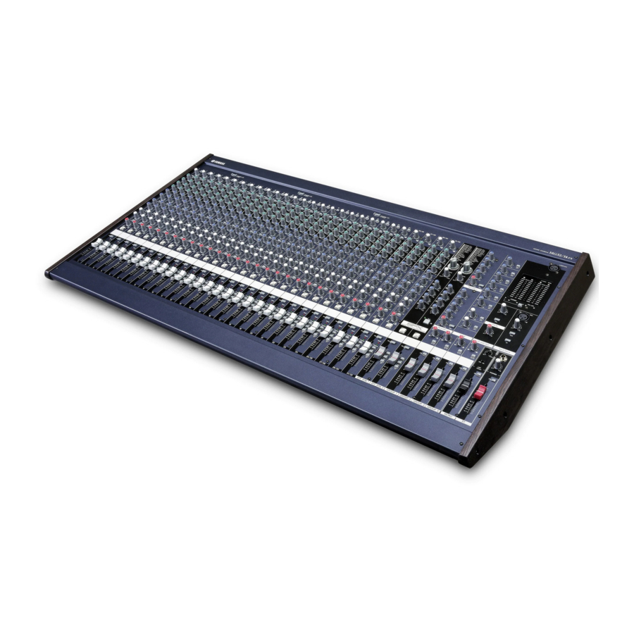
Thank you for your purchase of the YAMAHA MG32/14FX or MG24/14FX mixing console. This console offers excellent cost-performance and is ideal for use as the main mixer in an SR setup or as part of an installed system. Please read through this Owner’s Manual carefully before beginning use, so that you will be able to take full advantage of the mixer’s superlative features and enjoy trouble-free operation... -
Page 8: Connecting To Power
Connecting to Power (1) Be sure that the mixer’s power switch is off ( (2) Connect the socket end of the power cord to the AC IN connec- tor on the rear of the mixer. (3) Plug the other end of the power cord into a standard household power outlet. -
Page 9: Front Panel View
Front & Rear Panels Front Panel Channel Control Block MONAURAL CHANNELS Section (p. 10) STEREO CHANNELS Section (p. 10) MG32/14FX, MG24/14FX Note: Within this manual, all panel illustrations show the MG32/14FX panel. Master Control Block STEREO/MONO Section (p. 13) GROUP Section (p. 14) SEND Section (p. - Page 10 Rear Panel Rear Input/Output Block CHANNEL I/O Section (p. 19) MASTER I/O Section (p. 20) Front & Rear Panels Note: Within this manual, all panel illustrations show the MG32/14FX panel. MG32/14FX, MG24/14FX...
-
Page 11: Channel Control Block
Front & Rear Panels Channel Control Block I MONAURAL CHANNELS Section STEREO CHANNELS Section Monaural Channels 1 to 24 (MG32/14FX) 1 to 16 (MG24/14FX) MG32/14FX, MG24/14FX 1 PAD Switch 2 GAIN Control Stereo Channels 25/26 to 31/32 (MG32/14FX) 17/18 to 23/24 (MG24/14FX) 4 Equalizer Controls Band HIGH... - Page 12 5 AUX Controls (AUX1 to AUX6) These knobs adjust the channel’s signal levels into AUX buses 1 to 6. Each knob controls the signal into the corresponding AUX bus. For AUX1 to AUX4, you use the PRE switch (6) to select whether the pre-fader or post-fader signal is fed to the bus.
-
Page 13: Stereo Channels
Front & Rear Panels G PHANTOM +48 V Switch Toggles phantom power on or off to a set of eight adjacent channels. The MG32/14FX has three of these switches: for CHs 1 to 8, for CHs 9 to 16, and for CHs 17 to 24. The MG24/14FX has two: for CHs 1 to 8 and for CHs 9 to16. -
Page 14: Master Control Block
Master Control Block I STEREO/MONO Section You use this section to independently adjust the levels of the out- puts from the ST bus. You can independently adjust the main stereo output, the sub stereo output, and the mixed monaural output. 1 ST SUB OUT Control Adjusts the level of the signal that feeds from the ST bus into the ST SUB OUT jack (8 on page 20). - Page 15 Front & Rear Panels I GROUP Section This section adjusts the level and controls the flow of the signals from the four GROUP buses. While the signal from each GROUP bus is always fed into the corresponding GROUP OUT jack (see page 20), you are also free to use the TO ST and AFL switches to selectively feed these groups into the ST and AFL buses.
- Page 16 Front & Rear Panels I RETURN Section This section adjusts the levels of the input from the RETURN 1 and RETURN 2 jacks (see page 20). For each RETURN, you can set independent levels for feeds into the ST bus and AUX buses 1 to 4. 1 AUX Mix Controls (1 to 4) Each knob adjusts the level of the signal from the correspond- ing RETURN jack into the corresponding AUX bus (AUX1 to...
- Page 17 Front & Rear Panels I INTERNAL DIGITAL EFFECTS Section You use this section to control the dual internal effects processor: to select the two effect types, to set the effects on or off, and to adjust the related signal levels and flows. 1 PROGRAM Dials This dial sets the effect type for the corresponding internal dig- ital effect.
- Page 18 I METER/PHONES Section You use these meters to view various signal levels: the levels to the ST OUT jacks, the PFL and AFL levels, and the levels to the GROUP OUT jacks. The PFL or AFL signals indicated by these meters can be monitored through the PHONES jack.
- Page 19 Front & Rear Panels I TALK BACK Section 1 MIC Jack An unbalanced XLR input jack, for connection to a talkback microphone. This jack does not supply phantom power. N O T E 2 Talkback Control Adjusts the talkback level. 3 AUX1-4 Switch If this switch is on ( ), the mixer feeds the signal from the...
-
Page 20: Rear Input/Output Block
Rear Input/Output Block I CHANNEL I/O Section 1 Monaural-Channel Input Jacks (MG32/14FX: CHs 1 to 24, MG24/14: CHs 1 to 16) • INPUT A These are balanced XLR input jacks. • INPUT B These are balanced phone input jacks. You can connect either balanced or unbalanced phone plugs to these jacks. - Page 21 Front & Rear Panels I MASTER I/O Section 1 RETURN Jacks (1, 2) These are unbalanced phone input jacks. The signal into each of these jacks feeds into the ST bus and into AUX buses 1 to 4. These jacks are typically used to receive a return signal from an external effector (reverb, delay, etc.).
-
Page 22: Connector Polarities
This phone input jack is for connection to a foot switch, for use with the TAP DELAY feature. If you connect the (separately sold) YAMAHA FC5 foot switch to this jack and then set inter- nal EFFECT 2 to [16] TAP DELAY, you can use the foot switch (as an alternative to the TAP button) to set the delay. -
Page 23: Appendix
Specifications I General Specifications Frequency Characteristics (Master Output) Total Harmonic Distortion (Master Output) Hum and Noise (20 Hz - 20 kHz) Input GAIN = Maximum Input PAD = OFF Input sensitivity = –60 dBu Maximum Voltage Gain Monaural/Stereo Input Gain Control Monaural High Pass Filter Channel Input PAD Crosstalk (1 kHz) - Page 24 Where 0 dBu = 0.775 V and 0 dBV= 1 V Specifications and descriptions in this owner’s manual are for information purposes only. Yamaha Corp. reserves the right to change or modify products or specifications at any time without prior notice. Since specifications, equipment or options may not be the same in every locale, please check with your Yamaha dealer.
- Page 25 Appendix I Digital effect type list • Common to EFFECT 1 and 2 Type REVERB HALL Reverberation simulating a spacious expanse such as a concert hall. Reverb time REVERB ROOM Reverberation simulating the acoustics of a small room. REVERB PLATE Simulation of a plate reverb device.
-
Page 26: Dimensional Diagrams
Appendix Dimensional Diagrams I MG32/14FX 98.5 1027 Unit: mm I MG24/14FX 98.5 Unit: mm MG32/14FX, MG24/14FX... -
Page 27: Block And Level Diagram
Appendix Block and Level Diagram MG32/14FX, MG24/14FX... - Page 28 Appendix MG32/14FX, MG24/14FX...
- Page 29 Pour plus de détails sur les produits, veuillez-vous adresser à Yamaha ou au distributeur le plus proche de vous figurant dans la liste suivante. NORTH AMERICA CANADA Yamaha Canada Music Ltd. 135 Milner Avenue, Scarborough, Ontario,...
Need help?
Do you have a question about the MG24/14 FX and is the answer not in the manual?
Questions and answers