Table of Contents
Advertisement
I N S T R U C T I O N M A N U A L
950 Walnut Ridge Drive • Hartland, WI 53029-9388 • USA
Website: www.fotodyne.com • E-mail: info@fotodyne.com
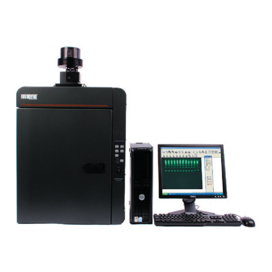
FOTO/Analyst
LuminaryFX Workstation
LED Modules
Cooled CCD camera
Motorized Lens
7-1720 series
Camera Model XL16 (FX/2.0)
7-1740 series
Camera Model C8484 (FX/HiQE)
WARNING
Read and understand this manual
before using this product.
Research Products Division
Technical Service:
Phone Orders:
Fax Orders:
®
262-369-7000
1-800-DNA-FOTO
(1-800-362-3686)
1-800-362-3642
Advertisement
Table of Contents

Summary of Contents for Fotodyne FOTO/Analyst LuminaryFX Workstation
- Page 1 7-1740 series Camera Model C8484 (FX/HiQE) WARNING Read and understand this manual before using this product. 950 Walnut Ridge Drive • Hartland, WI 53029-9388 • USA Website: www.fotodyne.com • E-mail: info@fotodyne.com Research Products Division Technical Service: 262-369-7000 Phone Orders: 1-800-DNA-FOTO...
-
Page 2: Table Of Contents
Fluorescent Imaging ..........16 Chemiluminescent Imaging using Timed Tab..18 Chemiluminescent Imaging using Multi Tab ..20 Additional Information Additional Information..........23 Servicing Information..........25 Ordering Information/Technical Assistance ....26 ©2011 FOTODYNE Incorporated Part # 78-8208 Rev B Part # 78-8208 Rev B... -
Page 3: Introduction
Introduction The FOTO/Analyst Luminary/FX Workstation is a multi-component system designed to simply and rapidly acquire images of a wide variety of specimens including gels, blots, and plates. Images are acquired by a CCD camera and transferred via a IEEE1394 (Firewire) board to a PC computer. Images can be archived in several file formats including TIF and BMP to preserve data integrity for downstream analysis. - Page 4 Introduction (cont.) ® ® IMPORTANT FEATURES OF YOUR FOTO/ANALYST IMPORTANT FEATURES OF YOUR FOTO/ANALYST Firewire Board (IEEE1394 bus)/PC Image Acquisition Firewire Board (IEEE1394 bus)/PC Image Acquisition LUMINARY/FX WORKSTATION Software Images from the CCD camera are acquired by the Firewire FOTO/Analyst Cooled CCD Cameras board which is to be installed into one of the PCI slots The FOTO/Analyst CCD (Charge Coupled Device) Camera in your PC computer.
- Page 5 Combinations of 254, 312 and 366 nm UV bulbs allow requiring epi-illumination - such as photographs, line- viewing of a variety of flourophores. All FOTODYNE drawings, Western blots, or TLC plates - can easily be transilluminators feature uniform illumination, a cooling acquired utilizing the direct lights.
-
Page 6: Specifications
Specifications FOTO/Analyst CCD Camera, 2.0 MegaPixel, FOTO/Analyst CCD Camera, 2.0 MegaPixel, FOTO/Analyst CCD Camera, 1.4 MegaPixel, FOTO/Analyst CCD Camera, 1.4 MegaPixel, Model XL16 (FX/2.0) Model C8484 (FX/HiQE) • 1600 x 1200 picture element array • 1344 x 1024 picture element array •... - Page 7 Specifications (cont.) Figure 2a Red light bank set emission curves, 6-7309 The first curve is the red LED emission curve (550-640 nm). The second curve is the red filter bandpass (650-710 nm). Figure 2b Blue light bank set emission curves, 6-7310 The first curve is the blue LED emission curve (460-495 nm).
-
Page 8: Safety Information
Safety Information WARNING CAUTION: Ultraviolet (UV) radiation can cause severe eye and skin damage! Do not view the UV light source with unprotected eyes. For maximum protection from skin damage, wear protective clothing and a UV blocking face shield over UV blocking eyeglasses. -
Page 9: Unpacking Instructions
Check-out Procedure Unpack and examine the FOTO/Analyst Luminary/FX Workstation carefully. Immediately report any damage to the transporting carrier and to FOTODYNE Incorporated. Be sure to save all cartons for claim purposes if damage is found. Identify the following components: LED Light Bank Set(s) FOTO/Analyst CCD Camera Assembly •... -
Page 10: Set-Up Instructions
Set-up Instructions Firewire Board Installation Remove Expansion Slot Cover. Remove Expansion Slot Cover. Remove the cover from the selected expansion slot (if applicable, retain the screw A Firewire board has been provided for your convenience. A Firewire board has been provided for your convenience. that held it in place;... -
Page 11: Ccd Camera Assembly
Set-Up Instructions CCD Camera Assembly, Camera Model XL16 (FX/2.0) CCD Camera Assembly, Camera Model XL16 (FX/2.0) Cable Connections Cable Connections (Figure 4a, page 10) Connect the FX Darkroom to the Computer. Attach the Camera Bracket to the FX Darkroom. Position the camera so the lens is facing down. Insert the Identify cable “D”. -
Page 12: Cable Diagram
Set-Up Instructions (cont.) Figure 4a FOTO/Analyst Luminary/FX Workstation Cable Connections for Camera Model XL16 (FX/2.0) Figure 4b FOTO/Analyst Luminary/FX Workstation Cable Connections for Camera Model C8484 (FX/HiQE) 78-8208 Rev C... -
Page 13: Led Module Connections
Set-Up Instructions (cont.) LED Light Module Connections LED Light Module Connections Transilluminator Installation Locate the LED Module Banks (Figure 5a). On the Warning: Always wear UV blocking eyeglasses whenever interior sides of the darkroom locate the LED Module setting up or operating a UV transilluminator to prevent Banks under the white LED sidelights. -
Page 14: Thermal Printer
DIP Switches. In the rear of the Thermal Printer there Open PC Image. are a series of switches which control many of the printing parameters. They have been factory-set at FOTODYNE Click on the File menu, choose System Options. The for the optimal performance for your application. Do not System Settings dialog box will appear. - Page 15 Set-Up Instructions (cont.) Set Darkroom Options. Click the Darkroom Options tab. This tab allows customization of the darkroom controls. If desired, click and highlight the button names to customize for your applications. For example, “Direct 2” could be changed to “red”. Check label in FX darkroom to determine actual settings for “Direct”...
-
Page 16: Operating Instructions
Operating Instructions Basic Gel Imaging Basic Gel Imaging Select Proper Filter. Select Proper Filter. Choose the appropriate filter by clicking the “^” button to the right of the filter choices in the CAUTION: Ethidium bromide is a known mutagen and filter wheel box. - Page 17 Operating Instructions (cont.) 10. Expose the image. 11. Save the Image. a. Click on the Save button in the Video Capture box. Click the button marked “Expose” in “Video Capture” box to start the integration. b. Type in the file name. c.
-
Page 18: Fluorescent Imaging
Operating Instructions (cont.) Fluorescent Imaging Frame and Focus the Subject. Frame and Focus the Subject. Position sample. Open the front access door to the Adjust the iris. Use the “Open” and “Close” buttons FOTO/Luminary Darkroom. Place subject in the center of next to “Iris”... - Page 19 Operating Instructions (cont.) Adjust Integration. In the box under the Expose 16. Save the Image. Save the Image. button, type the desired number of frames of a. Click on the Save button in the Video Capture box. integration. Alternatively, use the up or down buttons to find the optimal integration time.
-
Page 20: Chemiluminescent Imaging Using Timed Tab
Operating Instructions (cont.) Chemiluminescent Imaging: Chemiluminescent Imaging: Acquiring Images Using “Multi” Feature Position sample. Open the front access door to the FOTO/Luminary Darkroom. Remove the Lumi/Tray from its storage place on the inside of the door. Place subject in the center of the sample tray. Fit the tray into the track near the top of the enclosure, above the darkroom unit’s sidelights. - Page 21 Operating Instructions (cont.) 10. Turn off Direct 1 (white lights). 15. Choose and Save the image. Pick an image from the multiple exposures. Click on 11. Expose the image. the image. Set the number of frames of exposure in the “Exposure 1”...
-
Page 22: Chemiluminescent Imaging Using Multi Tab
Operating Instructions (cont.) Chemiluminescent Imaging: Acquiring Multiple Images Using “Timed” Feature Position sample. Open the front access door to the FOTO/Luminary Darkroom. Remove the Lumi/Tray from its storage place on the inside of the door. Place subject in the center of the sample tray (refer to Page 14). Fit the tray into the track near the top of the enclosure, above the darkroom unit’s sidelights. - Page 23 Operating Instructions (cont.) 11. Select the Settings button. Select the Settings button. 12. Expose the image. Adjustment of these settings may not be necessary before each use. If the settings achieve optimal image quality for Choose the total length of time the sample is to be a routine experiment, please go to Step 12.
- Page 24 Operating Instructions (cont.) Choose the number of increments and their durations. 13. Optional: Set other parameters. Optional: Set other parameters. Select Blk Lvl to indicate saturation of black subjects • Select the (ex: bands). “Increment (min/sec)” Select Sat to indicate any white areas of your image option.
-
Page 25: Additional Information
For images such as autorads, blots, or petri plates, a neutral gel image may be adjusted by changing these two param- density filter (FOTODYNE Catalog Number 60-2032) may eters in your Luminary/FX system. If a gel image is too light,... - Page 26 Additional Information (cont.) Acquire Acquire Multiple Exp Arrow Auto Level Black Level Brightness/Contrast Double Arrow Cascade Windows Crop (Select) Edit Drawing Ellipse Invert Line Mirror Horizontal Mirror Vertical New Window Open Image Print Rectangle Rotate Saturate Save Text Tool Color Tile Window_Horizontal Tile Window_Vertical Undo...
-
Page 27: Servicing Information
Servicing Information Adding or Replacing Filters If it becomes necessary to add or replace a filter in the motorized filter wheel, please contact FOTODYNE Incorporated for technical assistance at 1-800-362-3686. 78-8208 Rev C... -
Page 28: Ordering Information/Technical Assistance
Phone Orders: 1-800-DNA-FOTO 1-800-362-3686 Fax Orders: 1-800-362-3642 Mail to: 950 Walnut Ridge Drive Hartland, WI 53029-9388 Web-site: www.fotodyne.com • E-mail: technical.service@fotodyne.com TECHNICAL ASSISTANCE Technical questions regarding the operation and safe use of this instrument should be directed to FOTODYNE Incorporated. Call 1-262-369-7000.
Need help?
Do you have a question about the FOTO/Analyst LuminaryFX Workstation and is the answer not in the manual?
Questions and answers