
Related Manuals for Powrmatic PVU Series


Summary of Contents for Powrmatic PVU Series
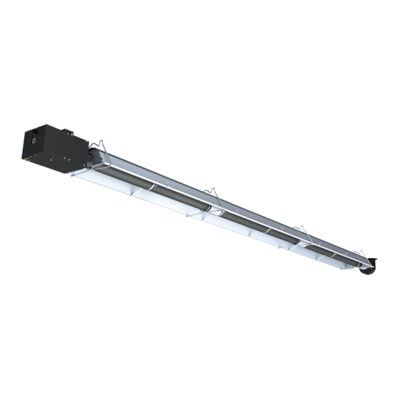
- Page 1 Doc Ref: M302 Issue 1.4 Oct 2019 ® PVU & PVL User, Installation & Servicing Manual Issue 1.4 Oct 2019 ErP COMPLIANT S E P T E M B E R 2 0 1 8 w w w . p o w r m a t i c . c o . u k...
- Page 2 1. The appliance type and serial number. 2. The original commissioning documentation. As much detail as possible on the fault. 3. Your supplier, or installer, will then contact Powrmatic to make a guarantee claim on your behalf. Conditions of Guarantee 1.
- Page 3 WARNING Improper installation, adjustment, alteration, service, or maintenance can cause property damage, injury or death. Read the installation, operation, and service instructions thoroughly before installing or servicing this equipment. FOR YOUR SAFETY Do not store or use flammable vapors and liquids in the vicinity of this or any other appliance. If you smell gas: 1.
-
Page 4: Table Of Contents
CONTENTS INTRODUCTION .................................... 4 .................................. 4 ODES AND EGULATIONS GENERAL SPECIFICATIONS ................................ 5 ...................................... 5 AS UPPLY ...................................... 5 LECTRIC UPPLY ................................. 5 ENTING AND OMBUSTION CONFIGURATIONS ................................... 5 DIMENSIONAL CHARTS .................................. 6 PACKAGING CONTENTS – PV L ................................. 7 – L .................................. 7 ENERAL SSEMBLY PACKAGING CONTENTS – PV U ................................ 8 –... -
Page 5: Introduction
Superior Radiant offers more than 20 years of infrared expertise in a cost effective unitary heater design as culmination of that commitment. Series PV model, the range of Superior Radiant Products (SRP®) from Powrmatic, is a low intensity infrared two stage tube heater with high radiant and thermal efficiency. -
Page 6: General Specifications
GENERAL SPECIFICATIONS Gas Supply Supply Pressure Nominal Minimum Maximum 20 mbar Natural Gas: 17.5 mbar 25 mbar 37 mbar Propane: 28 mbar 50 mbar Manifold Pressure Nominal Heat Input Partial Heat Input Natural Gas: 12.5 mbar 8 mbar Propane: 25 mbar 15.5 mbar Inlet Connection 1/2”... -
Page 7: Dimensional Charts
DIMENSIONAL CHARTS Figure 1: Overall Dimensional Information Model PV L Units 20LS 20/30 Dimensions 7975 9850 12900 19000 Weight Model PV U Units 20US 20/30 Dimensions 3875 5400 6950 10000 Weight Page 6 M301 Oct19 Series PVU/PVL... -
Page 8: Packaging Contents - Pv L
PACKAGING CONTENTS – PV L Get to know your heater parts (list referencing Figures 2 & 4). Figure 2: General Overview PV L General Assembly – PV L Quantities No. PN Description 20LS 20 30 40 50 1 CR002 End Cap 2 ... -
Page 9: Packaging Contents - Pv U
PACKAGING CONTENTS – PV U Get to know your heater parts (list referencing Figures 3 & 4). Figure 3: General Overview PV U General Assembly – PV U Quantities No. PN Description 20LS 20 30 40 50 1 CR002 End Cap 4 ... -
Page 10: General Assembly - Burner Box And Fan
General Assembly – Burner Box and Fan Quantities No. PN Description 20 30 40 50 1 CH223 Nut, M8 Hex 4 4 4 4 2 CH020 Spring Washer 4 4 4 3 CH001 Gasket, Flange 1 1 1 1 ‐ Choke Plate, Burner US250 US250 US250 ... -
Page 11: Clearances To Combustibles
CLEARANCES TO COMBUSTIBLES A general clearance of 500 mm (20”) in every direction is recommended for servicing. In addition to this, it is very important to observe the minimum clearances to combustibles at all times to avoid any possibility of property damage or personal injury. -
Page 12: Hangers Installation And Heater Suspension
HANGERS INSTALLATION AND HEATER SUSPENSION The heater should be installed in accordance with the relevant provisions of National standards and Codes of Practice in the destination country. Suspension mechanism must allow for lateral tubing expansion. A minimum 300 mm (12") length welded link chain with a working load limit of at least 90 kg (200 lbs) is recommended (refer to Figure 5 for more details). -
Page 13: Venting & Combustion Air
VENTING & COMBUSTION AIR General Requirements The heater should be installed in accordance with the relevant provisions of National Standards and Codes of Practice in the destination country. Heaters can be operated according to the following appliance type: Type A2. Gas appliance without flue gas system. The combustion air is taken from the installation space. Type B22. -
Page 14: Combustion Air Supply
Air Supply Air supply openings are required to admit air and shall be located below the radiant heaters. Exceptions are possible if the air supply openings are between the individual heaters and their location has been planned after proper evaluation of the air flow. The sum of the unobstructed cross-sections of all air supply openings shall not be smaller than the sum of the unobstructed cross-sections of all exhaust openings. -
Page 15: Supplying Fresh Air
Supplying Fresh Air Step 1 Remove the four nuts securing the Inlet Cage to the Burner Box. Do not remove the Gasket and Choke Plate. Step 2 Secure the Inlet Connector using the four M6 nuts. Flue Gas Exhaust Step 1 Remove the Screen from the Fan outlet. -
Page 16: Herringbone Manifold System
HERRINGBONE MANIFOLD SYSTEM The flue gas vacuum fan should position at the lowest point of the flue gas system. A condensate trap assembly must be provided at the end of the manifold system before the flue gas vacuum fan. To ensure that any condensation formed in the manifold is not trapped or allowed to drain back into the heater the manifold system should be arranged to fall slightly in the direction of the flue gas vacuum fan, 2 to 3 millimeters per meter. -
Page 17: Gas Supply
GAS SUPPLY General Requirements Before connecting gas to the heater, check the supply gas and supply pressure: match the information on the rating plate of the heater. The gas meter and service must be sufficiently large to supply gas to the connected building gas load ... -
Page 18: General Requirements Electrical Wiring
ELECTRICAL WIRING General Requirements The electrical wiring to this heater must be installed in accordance with National Standards and Codes of Practice in the destination country. This appliance must be earthed. Electrical supply 230V, 50Hz Power consumption 70W (Herringbone 15W) Current rating 0.3 A Internal Wiring Diagram This is a two stage heater. -
Page 19: Burner Operation
BURNER OPERATION Starting sequence of operation Turn the thermostat on. When the thermostat calls for heat, the fan motor will energize. After fan establishes the flow, the air-proving switch closes and activates the ignition sequence. The ignition module, after a pre-purge period of approximately 45 seconds, energizes the igniter. The gas valve opens after sparking starts. -
Page 20: Assembly Instructions Sequence - Pv L
ASSEMBLY INSTRUCTIONS SEQUENCE – PV L Step 1 The number of Hangers depends on the heater configuration; four to seven Hangers and Chains are required. All the chains must be aligned. Shortest chain length = 600 mm (Heaters 20 - 40 kW) 2800mm 3050mm Shortest chain length = 1000 mm (Heaters 50 kW) - Page 21 Step 6 Continue assembly by sliding Tubes through Hangers, and attaching all Couplings. Flanged Tube Length 3050mm (10’) 3050mm (10’) 3050mm (10’) 2800mm to (9’) Baffle Coupling Flanged Tube (Combustion) Gasket Tube (Heat Burner Exchanger) Choke Plate (Burner) Hangers Close all chain links “S” hooks, “J” bolts and turnbuckles or any open connection.
- Page 22 Step 9 Turbulators are ready to be inserted into the Tubes. Step 10 Bend Turbulator Tab down, tightly over the edge of the Tube. M8 Nut Washer Step 11 Install the Burner Box onto the flanged Tube. Refer to Packaging Contents page for part numbers and details.
- Page 23 Step 14 Reflector overlap orientations: PVL 20LS PVL 20/30 Step 15 Install the End Caps using U-clips. Step 16 Install Reflector Brackets (two parts that centralize the Tube within the Reflector). Refer to the diagram below for Free and Locked orientations.
- Page 24 Step 17 Wherever the Reflectors are overlapping, the Bracket must lock them together, except for the first overlap. Refer to the diagram below. Reflector Overlap Step 18 Attach Coupling to end of last tube and attach Fan. Orient Coupling and torque as described in Step 5. Connectors Cable Step 19...
-
Page 25: Assembly Instructions Sequence - Pv U
ASSEMBLY INSTRUCTIONS SEQUENCE – PV U Step 1 The number of Hangers depends on the heater configuration; two or three Hangers are required (consisting of a hanger kit and chain). All the chains must be aligned. Shortest chain length = 600 mm (Heaters 20 - 40 kW) 230mm (9”) 2670mm (105”) 230mm (9”) - Page 26 Step 2 Fasten the Tubes to the Hangers using the supplied U-bolts and nuts. Refer to Step 3 for number of nuts required on each Hanger. Ensure that the Tube’s weld seam faces downwards. Leave nuts finger tight until the end of assembly. 230mm (9”) Step 3 Circled U-bolts require four nuts,...
- Page 27 Step 6 Orient the Couplings to the 10 or 2 o’clock positions for nut accessibility. This will also prevent interference with the Reflector. Torque nuts to 20 – 35Nm. Step 7 Continue assembly by sliding Tubes through Hangers, and attaching all Couplings. Tube Length 3050mm (10’) Or 1525mm (5’)
- Page 28 Step 9 Twist the Turbulators 90 degrees to lock them together. Step 10 Turbulators are ready to be inserted into the Tubes. Step 11 Bend Turbulator Tab down, tightly over the edge of the Tube. Step 12 The reflectors will overlap each other as pictured here.
- Page 29 Step 14 Insert Reflector’s edge flange under the Middle Reflector Locator (detail in next step). Step 15 Repeat the above step for the second Reflector. Follow the same overlap sequence for the opposite side. Step 16 Install Side Reflector Locators. Refer to next step for details.
- Page 30 Step 18 Install Reflector Brackets (two pieces that centralize the tube within the reflector). Refer to the diagram showing Free and Locked positions for these Reflector 3mm (0.125”) Brackets. Locked Free Step 19 Install end caps using U-clips. Choke Plate (Burner) M8 Nut Step 20...
- Page 31 Completed Heater Page 30 M301 Mar19 Series PVU/PVL...
-
Page 32: Side Reflectors
SIDE REFLECTORS Step 1 Side Reflectors are 3150 mm (124”) long. Fasten one Side Reflector per Reflector with M4 x 5mm screws (not supplied). Use three Side Reflector Brackets per Side Reflector. Space about 1220 mm (48”) apart. Notch Tighten Nut Side Reflector Bracket (CR016) -
Page 33: Commissioning
COMMISSIONING Note: Use and complete this checklist before lighting the heater. Correct any conditions that do not meet these instructions. Heater assembly ˜ Radiant tube weld seam facing down ˜ Turbulators inserted at proper location. Turbulator tab bent over end of tube at 6 o'clock position. ˜... -
Page 34: Troubleshooting
TROUBLESHOOTING The burner has two display lamps, a yellow one and a red one. The yellow lamp indicates that the heater is running at full load. At partial load the yellow lamp is OFF. The red lamp indicates: Burner is operating when red lamp is ON. - Page 35 Troubleshooting Chart Page 34 M301 Mar19 Series PVU/PVL...
-
Page 36: Conversion Instructions
CONVERSION INSTRUCTIONS Adjusting the manifold pressure Check inlet and outlet pressure using the pressure test points provided. After testing, carefully seal test points with the provided screw. Remove the modulator plastic cap E Full load pressure: energize the modulator. Screw the nut C clockwise to increase the manifold pressure and screw it counter clockwise to decrease manifold pressure. -
Page 37: Replacement Parts
REPLACEMENT PARTS ITEM Part No. DESCRIPTION UE015 Indicator Light (Yellow) UE014 Indicator Light (Red) CE299 Ignition Module CG324 Gas Valve CE301 Fan Assembly CE003 Flame Sensor Electrode CE002 Spark Electrode UG001P Burner Cup CE319 Air Switch PV 20 CE319 Air Switch PV 30 CE320 Air Switch PV 40 CE319... -
Page 38: Replacing Parts
REPLACING PARTS WARNING ELECTRIC SHOCK & EXPLOSION HAZARD Disconnect electrical power and gas supply before servicing. Failure to do so may result in death or serious injury. Removal of Service Door and Combustion Door 1. Remove the two screws (A) to swing open the Service Doors. - Page 39 Removal of Module 1. Disconnect all the wires. 2. Remove the two screws and nuts and remove the module from the Burner Box. Removal of Air Switch 1. Disconnect the two clear hoses from the air switch and the two electrical connectors. 2.
- Page 40 Removal of Indicator Lights 1. Disconnect the wires from the Indicator Lights. 2. Press the tabs on either side the Indicator Light and remove from Burner Box. Page 39 M301 Mar19 Series PVU/PVL...
-
Page 41: Technical Details
TECHNICAL DETAILS Partial Heat Input Dimensions (mm) Heat Input (kW) Injector Weight (kW) Model Gross Gross mm (#) Natural gas PV 20 U 22.0 20.0 17.5 15.5 3.57 (#28) 3875 PV 30 U 30.5 27.5 25.0 22.5 4.22 (#19) 5400 PV 40 U 41.0 37.0... -
Page 42: Technical Details - Erp Directive
TECHNICAL DETAILS – ErP Directive Information required for eco-design (ErP) Directive 2009/125 Model 20 L 30 L 40 L 50 L 20 U 30 U 40 U Natural Gas 19.5 27.5 47.5 19.5 27.5 47.5 Heat Input (Net) 22.5 22.5 30.5 30.5 Heat Input (Gross) - Page 43 NOTES Page 41...
- Page 44 Energy Association Powrmatic pursues a policy of continues improvement in both design and performance of its products and therefore reserves the right to change, amend or vary specifications without notice. Whilst the details contained herein are believed to be correct they do not form the basis of any contract and interested parties should contact the Company to confirm whether any material alterations have been made since publication of this brochure.
Need help?
Do you have a question about the PVU Series and is the answer not in the manual?
Questions and answers