Advertisement
Quick Links
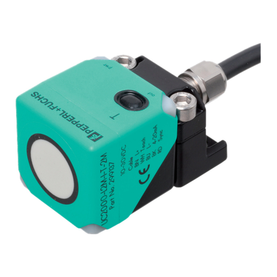
Inbetriebnahmeanleitung für Ultraschallsensor-Serie UC*-L2* mit 1 Analogausgang
Commissioning instruction for ultrasonic sensor series UC*-L2* with 1 analog output
BN
L+
GY
Synchronisation
WH
Lerneingang
BK
Analogausgang
BU
L-
1
L+
5
Synchronisation
2
Lerneingang
4
Analogausgang
3
L-
Beschreibung der Sensorfunktion
Produktinformationen
Weitere Informationen zum Produkt wie Technische Daten, Ansprechkurven, Maßzeichnungen etc. finden Sie auf der zugehörigen Produktseite
des Sensors auf www.pepperl-fuchs.de.
Einstellmöglichkeiten
Der Sensor ist mit 1 Analogausgang mit 2 programmierbaren Grenzen ausgestattet. Die Programmierung der Grenzen, der Ausgangsmodi sowie
der Schallkeulenbreite kann auf 3 verschiedene Arten vorgenommen werden:
•
Über den Lerneingang des Sensors (nur Programmierung der Grenzwerte)
•
Mittels Programmiertaste des Sensors
•
Über die serielle Schnittstelle des Sensors. Diese Methode erfordert einen externen Programmieradapter und die zugehörige Software. Sie
finden den Link zum Download der Software auf www.pepperl-fuchs.de auf der Produktseite des Sensors.
Hinweis
•
Die Möglichkeit der Programmierung besteht in den ersten 5 Minuten nach dem Einschalten. Sie verlängert sich während des Program-
miervorgangs. Nach 5 Minuten ohne Programmiertätigkeit wird der Sensor verriegelt. Danach ist kein Programmieren mehr möglich, bis der
Sensor aus- und eingeschaltet wird.
•
Bei aktiver Kommunikation über die serielle Schnittstelle des Sensors ist die Programmierung über die Progammiertaste oder den Lernein-
gang nicht möglich.
•
Es besteht jederzeit die Möglichkeit den Programmiervorgang abzubrechen, ohne Änderungen der Sensoreinstellung. Trennen Sie dazu
einfach den Sensor von der Versorgungsspannung.
Programmierung der Grenzen über die Programmiertaste
Analogausgangsmodi
nahe Grenze
ferne Grenze
(SP 1)
(SP 2)
Steigende Rampe
Fallende Rampe
Nullpunktgerade
Hinweis
Wenn das Objekt während des Programmiervorgangs korrekt erkannt wird, blinkt die gelbe LED. Eine blinkende rote LED während oder bei
Abschluss des Programmiervorgangs signalisiert eine unsichere Objekterkennung. Korrigieren Sie in diesem Fall während des Programmiervor-
gangs die Ausrichtung des Objekts, bis die gelbe LED blinkt. Nur so werden die Einstellungen in den Speicher des Sensors übernommen.
Programmierung der nahen Grenze (SP1)
1.
Positionieren Sie das Objekt am Ort der gewünschten nahen Grenze.
2.
Drücken Sie die Programmiertaste T für 2 s (gelbe LED blinkt).
3.
Drücken Sie die Programmiertaste T kurz (grüne LED blinkt 3x zur Bestätigung). Der Sensor kehrt in den Normalbetrieb zurück.
Programmierung der fernen Grenze (SP2)
1.
Positionieren Sie das Objekt am Ort der gewünschten fernen Grenze.
2.
Drücken Sie die Programmiertaste T für 2 s (gelbe LED blinkt).
3.
Drücken Sie die Programmiertaste T für 2 s (grüne LED blinkt 3x zur Bestätigung). Der Sensor kehrt in den Normalbetrieb zurück.
Programmierung der Grenzwerte der Analogkennlinie über den Lerneingang
Durch Anlegen von L+ oder von Masse (L-) am Lerneingang können Sie die Grenzwerte der Analogkennlinie einstellen.
Hinweis
• Vor Beginn des Programmiervorgangs muss der Lerneingang für mindestens 2 s unbeschaltet sein.
• Wenn der Lerneingang für >10 s mit L+ oder L- beschaltet wird, kehrt der Sensor ohne Änderung der Einstellungen in den Normalbetrieb
zurück. Um eine erfolgreiche Programmierung zu gewährleisten, lösen Sie die Verbindung zum Lerneingang vor Ablauf dieser Zeit.
• Wenn der Programmieradapter UB-PROG2 zur Programmierung verwendet wird, steht die Taste A1 für L- und die Taste A2 für L+.
Programmierung der nahen Grenze (SP1)
1. Positionieren Sie das Objekt am Ort der gewünschten nahen Grenze.
2. Verbinden Sie den Lerneingang für 2 s mit L- (gelbe LED blinkt, danach blinkt die grüne LED 3x zur Bestätigung). Anschließend kehrt der
Sensor in den Normalbetrieb zurück.
Programmierung der fernen Grenze (SP2)
1. Positionieren Sie das Objekt am Ort der gewünschten fernen Grenze.
2. Verbinden Sie den Lerneingang für 2 s mit L+ (gelbe LED blinkt, danach blinkt die grüne LED 3x zur Bestätigung). Anschließend kehrt der
Sensor in den Normalbetrieb zurück.
Programmierung der Sensorbetriebsarten
Der Sensor verfügt über eine 2-stufige Programmierung der Sensorbetriebsarten. In dieser Programmierroutine können Sie folgendes program-
mieren:
A) Ausgangsmodus
B) Schallkeulenbreite
Die Programmierung erfolgt nacheinander. Um von einem Programmierschritt in den nächsten zu wechseln, drücken Sie die Programmiertaste
für 2 s.
Die nachfolgende Grafik veranschaulicht die Programmierroutine:
T
T
LED grün
LED rot
5s
2s
Ausgangsmodus
Schallkeulenbreite
1x
1x
T
2x
T
2x
kurz
kurz
3x
3x
www.pepperl-fuchs.com
Subject to modification • Pepperl+Fuchs
EDM 45-5476 • Release 2018-12
Adernfarben gemäß EN 60947-5-2
1
BN
(braun)
2
WH
(weiß)
3
BU
(blau)
4
BK
(schwarz)
5
GY
(grau)
1
5
2
4
3
T
2s
Normalbetrieb
BN
L+
GY
Synchronization
WH
Teach input
BK
Analog output
BU
L-
1
L+
5
Synchronization
2
Teach input
4
Analog output
3
L-
Description of sensor function
Product information
Further information of the product such as technical data, response curves, dimensional drawings etc. you will find on the respective product
page for the sensor at www.pepperl-fuchs.com.
Adjustment possibilities
The sensor is equipped with 1 analog output with 2 programmable limits. The programming of the limits, the output mode and the beam width
can be done in 3 different ways:
•
Using the teach input of the sensor
•
By means of the sensor's programming button
•
Using the sensor's serial interface. This method requires an external programming adapter and the corresponding software. You will find the
download link for the software at www.pepperl-fuchs.com on the product page of the sensor.
Note:
•
The sensor can only be programmed during the first 5 minutes after switching on. This time is extended during the actual programming
process. The option of programming the sensor is revoked if no programming activities take place for 5 minutes. After this, programming is
no longer possible until the sensor is switched off and on again.
•
If communication via the sensor's serial interface is active, programming via the programming button or the teach input is not possible.
•
The programming process can be interrupted at any time without changing the sensor setting. Simply disconnect the sensor from the supply
voltage.
Programming the limits using the programming button
Analog output modes
Near limit
Far limit
(SP 1)
(SP 2)
Rising ramp
Falling ramp
Zero point line
Note:
If the target is detected stable during the programming procedure, this is indicated by a flashing yellow LED. If the red LED flashes during or at
the end of the programming procedure, it indicates an uncertain target detection. In this case, correct the target alignment during programming
procedure until the yellow LED flashes. The new settings are only stored in the sensor's memory if the yellow LED flashes.
Programming of the near limit (SP1)
1.
Place the object at the desired near limit position.
2.
Press the programming button T for 2 s (yellow LED flashes).
3.
Press the programming button T briefly (green LED flashes 3 times as confirmation). The sensor returns to normal mode.
Programming of the far limit (SP2)
1.
Place the object at the desired far limit position.
2.
Press the programming button T for 2 s (yellow LED flashes).
3.
Press the programming button T for 2 s (green LED flashes 3 times as confirmation). The sensor returns to normal mode.
Programming of the limits of the analog characteristic curve via the teach input
You can set the limits of the analog characteristic via the teach input by applying L+ or ground (L-).
Note
• Before starting the programming process, the teach input must be unconnected for at least 2 seconds.
• If the teach input is connected with L- or L+ for >10 s, the sensor returns to normal operation without changing the settings. To ensure success-
ful programming, disconnect the connection to the programming input before this time has elapsed.
• If the programming adapter UB-PROG2 is used for programming, the A1 key stands for L- and the A2 key for L+.
Programming of the near limit (SP1)
1. Place the object at the desired near limit position.
2. Connect the teach input to L- for 2 s (yellow LED flashes, then the green LED flashes 3 times to confirm). The sensor then returns to normal
operation.
Programming of the far limit (SP2)
1. Place the object at the desired far limit position.
2. Connect the teach input to L+ for 2 s (yellow LED flashes, then the green LED flashes 3 times to confirm). The sensor then returns to normal
operation.
Programming the modes of operation
The sensor provides a 2 step sequence for programming the modes of operation. In this programming sequence you can program the following:
A) Output mode
B) Beam width
Programming the modes is carried out sequentially. To toggle from one step to the next, press the programming button for 2 s.
The following graphic shows the structure of the programming sequence schematically:
T
LED green
T
LED red
5s
2s
Output mode
Beam width
1x
1x
T
T
2x
2x
short
short
3x
3x
Wire colors in accordance with EN 60947-5-2
1
BN
(brown)
2
WH
(white)
3
BU
(blue)
4
BK
(black)
5
GY
(gray)
1
5
2
4
3
T
2s
Normal
operation
Advertisement

Related Manuals for Pepperl+Fuchs UC L2 Series


Summary of Contents for Pepperl+Fuchs UC L2 Series
- Page 1 The following graphic shows the structure of the programming sequence schematically: Die nachfolgende Grafik veranschaulicht die Programmierroutine: LED green LED red LED grün LED rot Output mode Beam width Normal operation Ausgangsmodus Schallkeulenbreite Normalbetrieb short short kurz kurz www.pepperl-fuchs.com Subject to modification • Pepperl+Fuchs EDM 45-5476 • Release 2018-12...
- Page 2 Beachten Sie, dass das zur externen Synchronisation verwendete Gerät folgende Treiberfähigkeit besitzen muss: • Treiberstrom nach +UB > n x (High-Pegel/Eingangsimpedanz) • Treiberstrom nach 0V > n x Ausgangsstrom (n = Anzahl der zu synchronisierenden Sensoren) www.pepperl-fuchs.com Subject to modification • Pepperl+Fuchs EDM 45-5476 • Release 2018-12...
Need help?
Do you have a question about the UC L2 Series and is the answer not in the manual?
Questions and answers