Table of Contents

Related Manuals for Fluke Versiv Series


Summary of Contents for Fluke Versiv Series
- Page 1 Versiv Series ™ Cabling Certification Product Family Technical Reference Handbook Versiv Software Version 6.1 February 2018, Rev. 5 1/2019 ©2018-2019 Fluke Corporation All product names are trademarks of their respective companies.
- Page 2 LIMITED WARRANTY AND LIMITATION OF LIABILITY Each Fluke Networks product is warranted to be free from defects in material and workmanship under normal use and service unless stated otherwise herein. The warranty period for the mainframe is one year and begins on the date of purchase.
-
Page 3: Table Of Contents
Contents Chapter 1 Get Acquainted Overview of Features ............1 Versiv 2 Compatibility .............2 Contact Fluke Networks ..........2 Register Your Product ............3 Additional Resources ............3 Supplements and Updated Manuals ......3 Symbols ................4 Safety Information ..........6 For the Main Tester ..........6 For DSX Modules and Twisted Pair Adapters ..8 For CertiFiber Pro OLTS Modules ......10... - Page 4 Versiv Series Cabling Certification Product Family Technical Reference Handbook Number Format ............31 Units for Length Measurements ......31 Power-Down and Backlight Timeout Periods ..31 Audible Tone ............32 Power Line Frequency ..........32 Display Brightness ............ 33 Import User Preferences from a File ....... 33 How to Install a Strap ............
- Page 5 Contents Step 6: Do an Autotest in Smart Remote Mode .................50 Step 7: Look at the Results ........51 Step 8: Save the Results ...........51 Tutorial: Do a Bi-directional SmartLoop Test ....52 Step 1: See How Much Memory is Available ..53 Step 2: Set Up a Bi-directional SmartLoop Test ..53 Step 3: Turn Off the Auto Save Function ....55 Step 4: Enter IDs for the Fibers ........55...
- Page 6 Versiv Series Cabling Certification Product Family Technical Reference Handbook Make Sure Your Tester is Ready to Certify Twisted Pair Cabling ............81 Set the Reference ............82 Settings for Twisted Pair Tests ........84 How to Do an Autotest ..........90 “Bad Patch Cord”...
- Page 7 Contents Balance Measurements ..........133 Differential and Common-Mode Signals ..133 Effects of Unbalanced Impedance in a Wire Pair ..............133 Balance Measurements Available .....135 Resistance Unbalance ..........136 Resistance Unbalance within Pairs (PAIR UBL)..136 Resistance Unbalance Between Pairs (P2P UBL) ............140 CMRL (Common-Mode Return Loss) .......142 CDNEXT (Common-Mode to Differential-Mode Near-End Crosstalk) ...........144 TCL (Transverse Conversion Loss) ......147...
- Page 8 Versiv Series Cabling Certification Product Family Technical Reference Handbook Chapter 4 Test Twisted Pair Through a PoE Device (DSX-5000) How to Turn On the AC Wire Map Test ......159 When to Keep the AC Wire Map Test Off ....160 How to Do an Autotest Through a PoE Device ....
- Page 9 Contents Chapter 7 Clean Fiber Endfaces Always Clean Endfaces Before Tests ......207 How to Use a Fluke Networks Quick Clean Cleaner ................210 How to Use Wipes, Swabs, and Solvent ......212 To Clean Bulkhead Connectors ........212 To Clean the Optical Connectors on the Modules ..............213...
- Page 10 Versiv Series Cabling Certification Product Family Technical Reference Handbook How to See the Reference Values ....247 About Test Reference Cords and Mandrels .... 247 About the EF-TRC (Encircled-Flux Test Reference Cords) ..........248 About Standard Mandrels ........ 249 About APC Connectors ........250 Settings for Loss/Length Tests on Fiber ......
- Page 11 Contents Autotest Results for Loopback Mode ......278 Autotest in Far End Source Mode ........280 Auto Wavelength Modes .........280 Step 1: Set the Reference in Far End Source Mode ..........282 Step 2: Measure the Loss of the Test Reference Cord You Will Add ........286 Step 3: Do an Autotest in Far End Source Mode ..........287 Autotest Results for Far End Source Mode .....288...
- Page 12 Versiv Series Cabling Certification Product Family Technical Reference Handbook How To Compensate for Launch and Tail Cords ................. 321 Methods of Launch Compensation ....321 How to Set Up the Launch Compensation Function ............. 322 How To Enter Lengths Manually ...... 327 How To See the Launch Compensation Settings ..............
- Page 13 Contents How to Quickly Try Different OTDR Settings in Real Time Trace Mode ..........374 The SmartLoop Test ............376 How To Do an Auto SmartLoop Test ......378 Set Up SmartLoop Launch Compensation ..378 Do the SmartLoop Test ........380 SmartLoop Results ............382 Bi-directional SmartLoop Tests ........383 Why Do Bi-directional Tests? ........383 When To Do Bi-directional Tests ......384...
- Page 14 Versiv Series Cabling Certification Product Family Technical Reference Handbook OTDR Port Connection Quality ........418 If the Gauge is Not in the Good Range ....418 Port Connection Quality for SmartLoop Tests ..418 “STOP” Button for Manual Tests ......419 How to Do an HDR OTDR Test ........
- Page 15 Contents SmartLoop Results ............472 Bi-Directional SmartLoop Tests ........473 Why Do Bi-Directional Tests? ........473 When To Do Bi-Directional Tests ......474 How to Do a Bi-Directional SmartLoop Test ...474 Set Up SmartLoop Launch Compensation ..474 Do the SmartLoop Test ........475 Averaged Bi-Directional Results ......478 Chapter 13 OTDR Span and Event Editing Functions Overview of Features ............481...
- Page 16 Versiv Series Cabling Certification Product Family Technical Reference Handbook Causes of Loss/Length Test Failures ....... 496 Causes of OTDR Test Failures ......... 498 Chapter 16 Manage Test Results View Saved Results ............503 How to Add a Result to a Saved Result ......507 How to Replace a Saved Result that Failed ....
- Page 17 Contents Step 4: Make ID Sets for Twisted Pair and Fiber Cabling ............522 To see the CABLE ID SETUP screen ....522 To make a cable ID set for tests on twisted pair cabling ...........522 To make a cable ID set for tests on fiber cabling ..............524 Step 5: Give Names to the Ends of the Fiber for OTDR Tests ..........530...
- Page 18 Versiv Series Cabling Certification Product Family Technical Reference Handbook To use an ID that is not in an ID set that has a first and last ID ......... 542 To change the ID when the set has only a next ID ............. 543 To Change the Tests in a Project ......
- Page 19 Contents Use LinkWare Live Through a Wired Ethernet Network ................558 Use LinkWare Live Through a Wi-Fi Network ....559 When You Cannot Sync a Deleted Project ....563 Change the Network Settings ........563 Settings for the Wired Port ........564 Wi-Fi Settings ............564 Regulatory Information for the Wi-Fi Radio ..564 Delete Wi-Fi Settings and Passwords ......564 About the Asset Management Service ......566...
- Page 20 Versiv Series Cabling Certification Product Family Technical Reference Handbook Delete a Custom Fiber Type or Test Limit ....583 Chapter 20 Maintenance Verify Operation ............585 Clean the Tester ............. 586 Clean the FI-1000 Video Probe ........586 See Information About the Tester ........ 587 Update the Software .............
- Page 21 Contents DSX-8000 Module: Tests and Frequencies Supported ..............604 Twisted Pair Cabling ..........604 Coaxial Cabling (optional DSX-CHA003 coaxial adapters required) ........604 DSX-8000 Standard Link Interface Adapters ..604 DSX-CHA804 Cat 8/Class I Channel Adapters ..604 DSX-PLA804 Cat 8/Class I Permanent Link Adapters .............604 DSX-8000 Measurement Accuracy ......605 DSX-5000 CableAnalyzer Module Specifications ..609 DSX-5000 Times for a Full, 2-Way Autotest ....609...
- Page 22 Versiv Series Cabling Certification Product Family Technical Reference Handbook HDTDX Analyzer Specifications for Cables <100 m (328 ft) ..........616 HDTDR Analyzer Specifications for Cables <100 m (328 ft) ..........617 Characteristic Impedance ........617 Tone Generator ............617 Input Protection ............617 DSX-CHA003 Coaxial Adapter .........
- Page 23 Contents Appendix A Tests on Long Fiber Links with the OptiFiber Pro OTDR Make a Custom Fiber Type, If Necessary .......637 Use a Launch Cord of the Correct Type ......637 Use a Launch Cord of the Correct Length .....638 Use a Launch Cord that Has the Correct Connectors ..............638 Use the Correct Test Limit ..........639 For Tests on OSP Links ............639...
- Page 24 Versiv Series Cabling Certification Product Family Technical Reference Handbook xxii...
- Page 25 List of Figures Figure Page Main Unit Connectors, Keys, and LEDs (Versiv 2 shown)..14 Remote Unit Connectors, Keys, and LEDs (Versiv 2 shown) 16 LEDs Show the Remote’s Battery Status .......20 Connections to See the Status of the Remote’s Battery ..21 How to Zoom the Screen ............24 The HOME Screen (DSX CableAnalyzer screen shown)..26 Keyboards for Text Entry ............29...
- Page 26 Versiv Series Cabling Certification Product Family Technical Reference Handbook Remote DSX Tester Connectors, Keys, and LEDs (Versiv 2 shown)..............72 How to Attach and Remove Link Interface Adapters..74 How to Prevent Damage to the Permanent Link Adapter Cables ........... 75 DSX-8000 and DSX-5000 Module and Adapter Differences ................
- Page 27 List of Figures Return Loss Plot..............119 Twisted Pair Impedance Results ..........121 Near-End Crosstalk (NEXT).............122 NEXT Plot ................123 PS NEXT Plot ................124 Attenuation to Crosstalk Ratio, Near End (ACR-N) ....125 ACR-N Plot ................126 PS ACR-N Plot .................128 Far-End Crosstalk (FEXT) ............129 ACR-F Plot ................131 PS ACR-F Plot ................132 The Effects of EMI on Balanced and...
- Page 28 Versiv Series Cabling Certification Product Family Technical Reference Handbook Equipment for Tests on Coaxial Cabling ......170 Examples of Connections for Tests on Coaxial Cabling..171 Autotest Results for Coaxial Cabling ........172 Coaxial Length and Propagation Delay Results ....174 Coaxial Resistance Results .............
- Page 29 List of Figures 103. Remote CertiFiber Pro Tester Connectors, Keys, and LEDs (Versiv 2 with CFP-QUAD module shown)....237 104. How to Remove and Install the Connector Adapters ..240 105. The Home Screen for CertiFiber Pro Modules ......241 106. How to Prevent Damage to the EF-TRC Fiber Cables...249 107.
- Page 30 Versiv Series Cabling Certification Product Family Technical Reference Handbook 125. Connections to Monitor Power and Loss ......297 126. Power Meter Measurements and Controls ......298 127. Light Source Controls for the Main Tester ......301 128. Main Versiv Tester with OptiFiber Pro OTDR Module (Versiv 2 with OptiFiber Pro Quad module shown).....
- Page 31 List of Figures 151. Real Time Trace Screen (OptiFiber Pro module)....373 152. Manual OTDR Screen for Quick Changes to Settings in Real Time Trace Mode ............374 153. Equipment for SmartLoop Tests..........377 154. SmartLoop Launch Compensation Connections....379 155. SmartLoop Test Connections ..........381 156.
- Page 32 Versiv Series Cabling Certification Product Family Technical Reference Handbook 176. How to Use the Measurement Cursor on the ODTR Trace.. 450 177. Real Time Trace Screen (OptiFiber Pro HDR module)..457 178. Manual PON OTDR Screen for Quick Changes to Real Time Trace Settings ...............
- Page 33 List of Figures 202. Equipment for the OTDR Project Tutorial ......535 203. Equipment for the Loss/Length Project Tutorial ....536 204. Copper, OTDR, and Loss/Length Saved in a Project .....540 205. The CHANGE PROJECT Screen ..........546 206. SYNC PROJECTS Screen ............561 207.
- Page 34 Versiv Series Cabling Certification Product Family Technical Reference Handbook xxxii...
- Page 35 List of Tables Table Page Symbols ...................4 Power Button’s LED Indications for Versiv 2 Testers....18 Settings for Twisted Pair Tests..........84 dB Rules for ISO Test Limits ...........154 dB Rules for TIA Test Limits ...........154 Settings for Coaxial Tests............168 Remote Requirements for Coaxial Tests .......181 Causes of Twisted Pair Test Failures........187 Causes of Coaxial Test Failures ..........192 Settings for FiberInspector Tests ...........221...
- Page 36 Versiv Series Cabling Certification Product Family Technical Reference Handbook Custom Test Limit Settings for OTDR Tests ......580 Custom Test Limit Settings for FiberInspector Tests .... 581 Possible Solutions for Unusual Behavior ......599 Minimum Length of a Launch Cord........638 Reference Method Names for TIA/EIA Standards ....
-
Page 37: Chapter 1 Get Acquainted
The Versiv platform includes these features: Note Feature descriptions in the Versiv Series documentation apply to Versiv and Versiv 2 testers unless stated otherwise. ™... -
Page 38: Versiv 2 Compatibility
Performance Test Remote or the OneTouch AT Network Assistant modules. Contact Fluke Networks www.flukenetworks.com/support info@flukenetworks.com 1-800-283-5853, +1-425-446-5500 Fluke Networks 6920 Seaway Boulevard, MS 143F Everett WA 98203 USA Fluke Networks operates in more than 50 countries worldwide. For more contact information, go to our website. -
Page 39: Register Your Product
Chapter 1: Get Acquainted Register Your Product Register Your Product Registering your product with Fluke Networks gives you access to valuable information on product updates, troubleshooting tips, and other support services. If you purchased a Gold Support plan, registration also activates your plan. -
Page 40: Symbols
This Product contains a lithium-ion battery. Do not mix with the solid waste stream. Spent batteries should be disposed of by a qualified recycler or hazardous materials handler per local regulations. Contact your authorized Fluke Service Center for recycling information. Complies with California Energy Commission (CEC) requirements ... - Page 41 Chapter 1: Get Acquainted Symbols Table 1. Symbols (continued) Conforms to relevant Australian standards. 40 year Environment Friendly Use Period (EFUP) under China Regulation - Administrative Measure on the Control of Pollution Caused by Electronic Information Products. This is the period of time before any of the identified hazardous substances are likely to leak out, causing possible harm to health and the environment.
-
Page 42: Wsafety Information
Versiv Series Cabling Certification Product Family Technical Reference Handbook WSafety Information For the Main Tester Warning To prevent possible fire, electric shock, or personal injury: Read all safety information before you use the Product. Carefully read all instructions. - Page 43 Do not put in direct sunlight. Have an approved technician repair the Product. Use only AC adapters approved by Fluke Networks for use with the Product to supply power to the Product and charge the battery.
-
Page 44: For Dsx Modules And Twisted Pair Adapters
You can lose a USB flash drive, cause damage to it, or accidentally erase the contents of the drive. Thus, Fluke Networks recommends that you save no more than one day of test results on a flash drive or that you upload results to LinkWare Live. - Page 45 Chapter 1: Get Acquainted WSafety Information Do not operate the Product with covers removed or the case open. Hazardous voltage exposure is possible. Remove the input signals before you clean the Product. Do not put metal objects into connectors. Caution To prevent damage to the tester or cables under test, to prevent data loss, and to make sure your...
-
Page 46: For Certifiber Pro Olts Modules
Versiv Series Cabling Certification Product Family Technical Reference Handbook For CertiFiber Pro OLTS Modules Warning: Class 1 and Class 2 Laser Products To prevent possible eye damage caused by hazardous radiation: Do not look directly into optical connectors. Some optical equipment emits invisible radiation that can cause permanent damage to your eyes. -
Page 47: For Optifiber Pro Otdr Modules
Chapter 1: Get Acquainted WSafety Information Do not connect APC (angled physical contact) connectors to the output or input ports. An APC connector can damage the UPC fiber endface in the ports. To make sure your test results are as accurate as possible, do the reference procedure frequently. - Page 48 Versiv Series Cabling Certification Product Family Technical Reference Handbook Caution To prevent damage to the tester or cables under test: Do not connect the OTDR port to an optical source. Doing so can cause damage to the OTDR receiver.
-
Page 49: Main Unit Connectors, Keys, And Leds
Chapter 1: Get Acquainted Main Unit Connectors, Keys, and LEDs Main Unit Connectors, Keys, and LEDs See Figure 1 on page 14. For functions specific to modules, see these sections: “DSX CableAnalyzer Connectors, Keys, and LEDs” on page 70 “CertiFiber Pro Connectors, Keys, and LEDs”... - Page 50 Versiv Series Cabling Certification Product Family Technical Reference Handbook GPU10.EPS Figure 1. Main Unit Connectors, Keys, and LEDs (Versiv 2 shown) LCD display with touchscreen. Bay for modules, such as the DSX CableAnalyzer, CertiFiber Pro, or OptiFiber Pro modules, or the blank module for the FI-7000.
- Page 51 USB flash drive and connect the FI-1000 video probe to the tester. On a Versiv main tester, this port lets you connect a Wi-Fi adapter for access to the Fluke Networks cloud service LinkWare Live. (Versiv 2 testers have an internal Wi-Fi radio.) ...
- Page 52 Versiv Series Cabling Certification Product Family Technical Reference Handbook GPU147.EPS Figure 2. Remote Unit Connectors, Keys, and LEDs (Versiv 2 shown) PASS LED comes on when a test passes. TEST LED flashes during a test. FAIL LED comes on when a test fails.
-
Page 53: Ac Adapter And Battery
Chapter 1: Get Acquainted AC Adapter and Battery LOW BATTERY LED comes on when the battery is low. The LEDs also have these functions: Battery gauge (see Figure 3 on page 20) Volume indicator for the TALK function Progress indicator for software updates ... -
Page 54: Charge The Battery
Versiv Series Cabling Certification Product Family Technical Reference Handbook Charge the Battery Before you use the battery for the first time, charge the battery for about 2 hours with the tester turned off. To charge the battery Connect the AC adapter to the 15V jack on the left side of the tester. -
Page 55: Check The Battery Status
Chapter 1: Get Acquainted AC Adapter and Battery Table 2. Power Button’s LED Indications for Versiv 2 Testers Red, steady: The tester is on and the battery is charging. The LED stays red for a few minutes after the battery status icons show that the battery is fully charged. -
Page 56: Mode
Versiv Series Cabling Certification Product Family Technical Reference Handbook On a remote The LEDs show the battery status at the end of the power-up sequence, as shown in Figure 3. 84 % - 100 % 67 % - 83 %... - Page 57 Chapter 1: Get Acquainted AC Adapter and Battery When the ac adapter is not connected, the screen shows the Time Remaining, which is the approximate battery life at the present rate of use. DSX CableAnalyzer modules with permanent link and channel adapters DSX CableAnalyzer modules with two channel adapters...
-
Page 58: Verify Operation
Versiv Series Cabling Certification Product Family Technical Reference Handbook Verify Operation The tester does a self test when you turn it on. If the tester shows an error or does not turn on, refer to “If the Tester Does Not Operate as Usual”... - Page 59 Chapter 1: Get Acquainted How to Use the Touchscreen When you zoom a trace or plot horizontal and vertical zoom controls show on the screen. These controls let you change the magnification on the distance and decibels scales independently. You can zoom in to a maximum magnification factor of 128:1. ...
- Page 60 Versiv Series Cabling Certification Product Family Technical Reference Handbook To move the image, drag it in To zoom in, use the reverse- any direction. pinch gesture or the horizontal and vertical zoom controls. To quickly go back to 1:1 To zoom out, use the pinch...
-
Page 61: The Home Screen
Chapter 1: Get Acquainted The HOME Screen The HOME Screen The HOME screen (Figure 6) shows important test settings. Before you do a test, make sure these settings are correct. For a home screen with a DSX CableAnalyzer module installed, see Figure 26 on page 78. - Page 62 Versiv Series Cabling Certification Product Family Technical Reference Handbook Note You can set up tests for any module that the tester can use, even when no module is attached. GPU98.EPS Figure 6. The HOME Screen (DSX CableAnalyzer screen shown) For copper test setups, icons show the status of the Store Plot ...
- Page 63 Chapter 1: Get Acquainted The HOME Screen Enter an ID, select a different ID in the ID set, select a different set of IDs, or make a new set. The tester adds the IDs and ID sets you make to the project that shows on the home screen.
-
Page 64: How To Enter Text
Versiv Series Cabling Certification Product Family Technical Reference Handbook Sets with International Characters” on page 550 for more information about the Next ID list. The type of module attached to the tester. If no module is attached, this screen shows HOME. - Page 65 Chapter 1: Get Acquainted How to Enter Text To move the cursor into a group of characters, tap on the group. To select a group of characters, double-tap on the group. To enter symbols or accented letters, tap , then ...
-
Page 66: Set User Preferences
Versiv Series Cabling Certification Product Family Technical Reference Handbook Set User Preferences User preferences are settings you usually change when you use the tester for the first time. Note You can use LinkWare PC software to make a file that contains settings for user preferences, then you can install the settings in one or more testers. -
Page 67: Number Format
Chapter 1: Get Acquainted Set User Preferences To set the date format, tap Date Format, then tap a format for the day (DD), month (MM), and year (YYYY). To set the time format to 12-hour clock or a 24-hour clock, ... -
Page 68: Audible Tone
Versiv Series Cabling Certification Product Family Technical Reference Handbook Tap Timeout Period, then tap Backlight or Power Down. Tap a time. To always keep the backlight or tester on, tap Disabled. To go back to the home screen, tap two times or press . -
Page 69: Display Brightness
If one of the types is not included with your tester, you can purchase it from an authorized Fluke Networks distributor. Figure 8 shows how to install a strap and how to use... -
Page 70: How To Remove Or Install A Module
Versiv Series Cabling Certification Product Family Technical Reference Handbook GPU43.EPS Figure 8. How to Install a Strap and Use the Hand Strap How to Remove or Install a Module Figure 9 shows how to remove and install the module. Note It is not necessary to turn off the tester before you remove or install a module. - Page 71 Chapter 1: Get Acquainted How to Remove or Install a Module Removal Installation Caution To prevent damage to the case, push the latches down ( before you turn them ( GPU20.EPS Figure 9. How to Remove and Install a Module...
-
Page 72: About Linkware Applications
PC, organize and examine test results, print professional-quality test reports, and do software updates and other maintenance procedures on your tester. You can download LinkWare PC from the Fluke Networks website. The LinkWare Live Web Application The LinkWare Live web application lets you manage projects from a desktop or mobile device. -
Page 73: Chapter 2 Get Started
Chapter 2: Get Started Warning Before you use the tester, read the safety information that starts on page 6. Tutorial: Certify Twisted Pair Cabling The tutorial in this section gives instructions on how to set up a test to certify twisted pair cabling, do the test, and save the results. -
Page 74: Step 1: See How Much Memory Is Available
Versiv Series Cabling Certification Product Family Technical Reference Handbook Step 1: See How Much Memory is Available On the home screen, tap the TOOLS icon, then tap Memory Status. The MEMORY STATUS screen shows these values: The percentage of memory available The number of test records that are saved ... - Page 75 Chapter 2: Get Started Tutorial: Certify Twisted Pair Cabling If you do not see the correct cable type, tap MORE, tap the name of a cable group, then tap a cable in the group. NVP: Nominal velocity of propagation, which the tester ...
-
Page 76: Step 3: Turn Off The Auto Save Function
Versiv Series Cabling Certification Product Family Technical Reference Handbook If the correct outlet configuration does not show, tap Outlet Configuration. On the OUTLET CONFIG screen, tap the correct configuration, then tap USE SELECTED. AC Wire Map: This setting lets you do tests on links connected through midspan PoE (Power over Ethernet) devices. -
Page 77: Step 6: Save The Results
Chapter 2: Get Started Tutorial: Certify Twisted Pair Cabling WIRE MAP: Shows the connections between the ends of the cable. PERFORMANCE: Shows the overall result for each test. Use this screen to quickly see which test failed. Plot and tabular results screens: Tap a test on the ... - Page 78 Versiv Series Cabling Certification Product Family Technical Reference Handbook GPU103.EPS Figure 11. Examples of Twisted Pair Autotest Results Screens...
-
Page 79: Tutorial: Certify Fiber Optic Cabling
Chapter 2: Get Started Tutorial: Certify Fiber Optic Cabling Tutorial: Certify Fiber Optic Cabling The tutorial in this section gives instructions on how to set up a loss/length test in Smart Remote mode to certify fiber optic cabling, and save the results. Figure 12 shows the minimum equipment necessary for this tutorial. - Page 80 Versiv Series Cabling Certification Product Family Technical Reference Handbook GPU143.EPS Main and remote testers with Duplex fiber link or segment CertiFiber Pro modules installed Fiber cleaning supplies For multimode fiber: two EF-TRC FI-1000 video probe with USB...
-
Page 81: Step 2: Set Up A Loss/Length Test
Chapter 2: Get Started Tutorial: Certify Fiber Optic Cabling Step 2: Set Up a Loss/Length Test Attach CertiFiber Pro modules to the main tester and the remote. On the home screen, tap the test setup panel. On the CHANGE TEST screen, tap NEW TEST. On the TEST SETUP screen, tap each setting to make these selections: Module: This is the module you will use for the test. -
Page 82: Step 3: Turn Off The Auto Save Function
Versiv Series Cabling Certification Product Family Technical Reference Handbook Test Limit: The test limit specifies the limits for measurements so that the tester can give a PASS or FAIL result to the test. The TEST LIMIT screen shows the last 10 limits that were selected. -
Page 83: Step 4: Set The Reference
Chapter 2: Get Started Tutorial: Certify Fiber Optic Cabling Step 4: Set the Reference The reference procedure for fiber cable sets a baseline power level for loss measurements. It is important to set the reference frequently for loss/length tests. Turn on the tester and remote and let them sit for a minimum of 5 minutes. - Page 84 Versiv Series Cabling Certification Product Family Technical Reference Handbook Caution Do not disconnect the outputs ( ) after you set the reference. When you use the EF-TRCs, DO NOT use other mandrels. Test reference cord Fiber link Test reference cord...
-
Page 85: Step 5: Measure The Loss Of The Test Reference Cords You Will Add
Chapter 2: Get Started Tutorial: Certify Fiber Optic Cabling Step 5: Measure the Loss of the Test Reference Cords You Will Add Caution If you disconnected a test reference cord from the output of the tester or remote, you must set the reference again to make sure your measurements are reliable. - Page 86 Versiv Series Cabling Certification Product Family Technical Reference Handbook Step 6: Do an Autotest in Smart Remote Mode Caution If you disconnected a test reference cord from the output of the tester or remote, you must set the reference again to make sure your measurements are reliable.
-
Page 87: Step 7: Look At The Results
Chapter 2: Get Started Tutorial: Certify Fiber Optic Cabling Step 7: Look at the Results The tester shows the Autotest results in two formats (Figure 14): The first screen shows the worst-case results for each fiber. To see more details about a fiber, tap a result window. GPU144.EPS Figure 14. -
Page 88: Tutorial: Do A Bi-Directional Smartloop Test
Versiv Series Cabling Certification Product Family Technical Reference Handbook Tutorial: Do a Bi-directional SmartLoop Test The tutorial in this section gives instructions on how to set up for a bi-directional SmartLoop test, set up the launch compensation function, make connections, do a test, and save the results. -
Page 89: Step 1: See How Much Memory Is Available
Chapter 2: Get Started Tutorial: Do a Bi-directional SmartLoop Test Step 1: See How Much Memory is Available On the home screen, tap the TOOLS icon, then tap Memory Status. The MEMORY STATUS screen shows these values: The percentage of memory available The number of test records that are saved ... - Page 90 Versiv Series Cabling Certification Product Family Technical Reference Handbook Note You can select settings for any module that the tester can use. It is not necessary to install a module before you set up a test for that module. Test Type: Make sure the Test Type is SmartLoop OTDR ...
-
Page 91: Step 3: Turn Off The Auto Save Function
Chapter 2: Get Started Tutorial: Do a Bi-directional SmartLoop Test Step 3: Turn Off the Auto Save Function For this tutorial, you will manually save the test results. On the home screen, tap the Next Fiber A ID/Next Fiber B ID panel. - Page 92 Versiv Series Cabling Certification Product Family Technical Reference Handbook Tap SAVE. The tester shows the lengths of the three cords, and the time and date when you saved the launch compensation settings. Loopback cord OTDR port protector Adapters patch cord...
- Page 93 Chapter 2: Get Started Tutorial: Do a Bi-directional SmartLoop Test GPU199.EPS Figure 17. SET LAUNCH COMP Screen for the SmartLoop Test The distances shown are relative to the end of the launch cord, which is at 0.00 m. The loopback cord is 105.07 m long, so the tail cord starts at ...
-
Page 94: Step 6: Do The Smartloop Test
Versiv Series Cabling Certification Product Family Technical Reference Handbook If necessary, you can look at the OTDR trace to identify launch and tail events and see the quality of the connections. Step 6: Do the SmartLoop Test Clean and inspect the connectors on the fiber link. - Page 95 Chapter 2: Get Started Tutorial: Do a Bi-directional SmartLoop Test Loopback cord Loopback cord (Tail Cord for (Tail Cord for Fiber B and Fiber A and Launch Cord for Launch Cord for Fiber A) Fiber B) OTDR Port event End event End event OTDR Port event for Fiber B...
-
Page 96: Step 7: Look At The Results
Versiv Series Cabling Certification Product Family Technical Reference Handbook Step 7: Look at the Results The tester shows the SmartLoop results in three formats (Figure 19): EventMap: Shows a diagram of the events on the fiber, the fiber length, and the overall loss of the fiber. -
Page 97: Step 8: Save The Results
Chapter 2: Get Started Buttons to Do Tests and Save Results GPU26.EPS Figure 19. Examples of the EventMap, TABLE, and TRACE Screens Step 8: Save the Results Tap SAVE (or FIX LATER if the test failed). The SAVE RESULTS screen shows the IDs you entered. - Page 98 Versiv Series Cabling Certification Product Family Technical Reference Handbook GPU40.EPS Figure 20. FIX LATER, TEST AGAIN, and TEST Buttons and the TEST Key SAVE (yellow), TEST (gray): These buttons show if the test passed and Auto Save is off. When you tap SAVE, you can save the results with an ID that you make or select.
- Page 99 Chapter 2: Get Started Buttons to Do Tests and Save Results When you look at a saved result that failed, tap TEST AGAIN to do the test again for the same ID and with the same test settings as the saved result. Note The color of the FIX LATER and TEST AGAIN buttons (yellow or gray) depends on which button...
-
Page 100: Options For Cable Ids
Versiv Series Cabling Certification Product Family Technical Reference Handbook Options for Cable IDs When you save the test results for a cable, you usually give the results the name that is the ID for the cable. There are several methods you can use to make IDs for test results: ... -
Page 101: Automatic Increment Function For Cable Ids
Chapter 2: Get Started Options for Cable IDs Automatic Increment Function for Cable IDs Each time you save a result, the tester automatically saves the result with the next ID in the set. It is not necessary for the IDs in a set to be sequential. -
Page 102: Tutorial: Make A Set Of Sequential Cable Ids
Versiv Series Cabling Certification Product Family Technical Reference Handbook If Auto Save is on and the test failed: To saved the failed result before you do a test for the next ID, tap FIX LATER. To do the test again for the same ID, tap TEST AGAIN. - Page 103 Chapter 2: Get Started Options for Cable IDs To make a set of sequential IDs Example: You will do tests on four cables (A through D) in 10 rooms (01 through 10) on the first and second floors, for a total of 80 cables.
-
Page 104: About Projects
Versiv Series Cabling Certification Product Family Technical Reference Handbook About Projects ™ The ProjX management system lets you set up a project to specify the settings necessary for a job, to monitor the status of a job, and organize your test results. See Chapter 17. -
Page 105: Chapter 3 Certify Twisted Pair Cabling
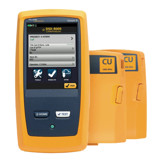
(1000 MHz) in less than 6 seconds. Gives a PASS or FAIL result based on a test limit that you specify. AxTalk software, which is available on the Fluke Networks website, lets you do tests for alien crosstalk. -
Page 106: Dsx Cableanalyzer Connectors, Keys, And Leds
Versiv Series Cabling Certification Product Family Technical Reference Handbook DSX CableAnalyzer Connectors, Keys, and LEDs DSX-8000 GPU88.EPS Figure 21. Main DSX Tester Connectors, Keys, and LEDs (Versiv 2 shown) Connector for a link interface adapter DSX-8000 modules have a recess for the tabs on Cat 8/Class I/II adapters. - Page 107 The LED is yellow if the battery will not charge. See “Charge the Battery” on page 18. RJ45 connector: Lets you connect to a network for access to Fluke Networks cloud services.
- Page 108 Versiv Series Cabling Certification Product Family Technical Reference Handbook DSX-8000 GPU42.EPS Figure 22. Remote DSX Tester Connectors, Keys, and LEDs (Versiv 2 shown) Connector for a link interface adapter DSX-8000 modules have a recess for the tabs on Cat 8/Class I/II adapters.
- Page 109 Chapter 3: Certify Twisted Pair Cabling DSX CableAnalyzer Connectors, Keys, and LEDs PASS LED comes on when a test passes. TEST LED flashes during a test. FAIL LED comes on when a test fails. TALK LED comes on when the talk function is on ( ).
-
Page 110: About Link Interface Adapters
Versiv Series Cabling Certification Product Family Technical Reference Handbook About Link Interface Adapters Link interface adapters let you connect the DSX CableAnalyzer to different types of twisted pair links. Figure 23 shows how to attach and remove adapters. GPU109.EPS Figure 23. How to Attach and Remove Link Interface Adapters... - Page 111 Chapter 3: Certify Twisted Pair Cabling About Link Interface Adapters 5 in (13 cm) minimum GPU108.EPS Figure 24. How to Prevent Damage to the Permanent Link Adapter Cables...
-
Page 112: Adapters For Dsx-8000 And Dsx-5000 Modules
Versiv Series Cabling Certification Product Family Technical Reference Handbook Adapters for DSX-8000 and DSX-5000 Modules You can use adapters for test limits up to Cat 7 /Class F coaxial adapters with DSX-8000 and DSX-5000 modules. Be sure to select a test limit that is appropriate for the adapter. - Page 113 Chapter 3: Certify Twisted Pair Cabling Adapters for DSX-8000 and DSX-5000 Modules Tabs Cat 8/Class I/II and recess adapter DSX-8000 Module For test limits up to Cat 8/ Class I/II Cat 8/Class I/II adapters attach only to DSX-8000 modules ...
-
Page 114: The Dsx Cableanalyzer Home Screen
Versiv Series Cabling Certification Product Family Technical Reference Handbook The DSX CableAnalyzer Home Screen The home screen (Figure 26) shows important test settings. Before you do a test, make sure these settings are correct. MN O GPU110.EPS Figure 26. The Home Screen for DSX CableAnalyzer PROJECT: The project contains the settings for a job and helps ... - Page 115 Chapter 3: Certify Twisted Pair Cabling The DSX CableAnalyzer Home Screen Shows a summary of the test results in the project: The number of tests that passed. The number of tests that failed. The number of results from tests on twisted pair cable that have PASS* results.
- Page 116 Versiv Series Cabling Certification Product Family Technical Reference Handbook TOOLS: The TOOLS menu lets you set the reference, see the status of the tester, and set user preferences such as the language and the display brightness. RESULTS: Tap RESULTS to see and manage the results that are saved in the tester.
-
Page 117: Make Sure Your Tester Is Ready To Certify Twisted Pair Cabling
Make sure the cords and connectors for all test equipment and patch cords are in good condition. Make sure the battery is fully charged. Send the modules to a Fluke Networks service center every 12 months for factory calibration. -
Page 118: Set The Reference
Versiv Series Cabling Certification Product Family Technical Reference Handbook Set the Reference The reference procedure for twisted pair cable sets the baseline for insertion loss, ACR-F, and DC resistance measurements. Set the reference at these times: When you want to use the tester with a different module. The tester can save reference values for eight different pairs of modules. - Page 119 Chapter 3: Certify Twisted Pair Cabling Set the Reference Permanent link Channel adapter adapter For DSX-8000 modules, use Cat 8/Class I/II adapters Reference artifact DSX-8000: DSX-CALIBRATION 2G DSX-5000: DSX-CALIBRATION GPU89.EPS Figure 27. Reference Connections for Twisted Pair Cable...
-
Page 120: Settings For Twisted Pair Tests
Versiv Series Cabling Certification Product Family Technical Reference Handbook Settings for Twisted Pair Tests Table 3 gives descriptions of the settings for twisted pair tests. To set up a project, which includes the settings in Table 3, cable IDs, and operator names, see Chapter 17. - Page 121 Chapter 3: Certify Twisted Pair Cabling Settings for Twisted Pair Tests Table 3. Settings for Twisted Pair Tests (continued) Nominal velocity of propagation. The tester uses the NVP and the propagation delay to calculate the length of the cable. The default value is defined by the selected cable type and is the typical NVP for that cable type.
- Page 122 Versiv Series Cabling Certification Product Family Technical Reference Handbook Table 3. Settings for Twisted Pair Tests (continued) : The tester does not save plot data for Store Plot Data frequency-domain tests or for the HDTDR/HDTDX analyzers. You can see the plots before you save the test and exit the results screen.
- Page 123 Chapter 3: Certify Twisted Pair Cabling Settings for Twisted Pair Tests Table 3. Settings for Twisted Pair Tests (continued) The Outlet Configuration specifies which wire pairs are Outlet Configuration tested and which wire numbers the wire map shows for the pairs.
- Page 124 Versiv Series Cabling Certification Product Family Technical Reference Handbook Crossover T568A T568B Rollover 1000BASE-T Crossover 2 x Two-Pair Crossed Ethernet Token Ring Ethernet Two-Pair Two-Pair Crossed CSU/DSU USOC Two-Pair USOC Single-Pair ATM/TP-PMD ATM/TP-PMD One Pair (1,2) Straight Crossed GPU85.EPS Figure 28. Outlet Configurations - RJ45...
- Page 125 Chapter 3: Certify Twisted Pair Cabling Settings for Twisted Pair Tests M12-D Two-Pair M12-D Two-Pair Crossed ™ M12 X-Code ix Industrial Ethernet GPU238.EPS Figure 29. Outlet Configurations - Industrial Ethernet...
-
Page 126: How To Do An Autotest
Versiv Series Cabling Certification Product Family Technical Reference Handbook How to Do an Autotest When you tap TEST on the main tester or press on the main or remote tester, the testers do an Autotest. The Autotest includes all the tests necessary to certify that the cabling meets or exceeds the performance requirements specified in the selected test limit. - Page 127 Chapter 3: Certify Twisted Pair Cabling How to Do an Autotest To do an Autotest on twisted pair cable Attach permanent link or channel adapters to the main and remote testers. Make sure that the home screen shows the correct settings for the job.
- Page 128 Versiv Series Cabling Certification Product Family Technical Reference Handbook Horizontal cabling Optional consolidation point Patch panel Wall outlet Start permanent permanent link link Tester with Remote with permanent link permanent link adapter adapter GPU97.EPS Figure 31. Permanent Link Connections for Links Up to Cat 7...
- Page 129 Chapter 3: Certify Twisted Pair Cabling How to Do an Autotest Horizontal cabling Hub or switch Optional consolidation point Patch cord Wall from hub outlet or switch Patch Patch cord panels from PC Start channel channel Tester with Remote with channel adapter channel adapter GPU96.EPS...
- Page 130 Versiv Series Cabling Certification Product Family Technical Reference Handbook Hub or switch Horizontal cabling (24 m maximum) Patch cord Patch cord from from PC hub or switch Start channel channel Tester with DSX-8000 Remote with DSX-8000 module and Cat 8/Class I...
-
Page 131: Bad Patch Cord" Message
Adapters and the correct patch cord test limit. You cannot use channel adapters and test limits to certify patch cords because channel tests do not measure the performance of the patch cord plugs. To purchase a DSX-PCxxS Patch Cord Adapter Set, contact an authorized Fluke Networks distributor. -
Page 132: Twisted Pair Autotest Results
Versiv Series Cabling Certification Product Family Technical Reference Handbook Twisted Pair Autotest Results The tests listed below apply to twisted pair cabling. Note Some tests are not included in some test limits. Wire map Resistance Resistance unbalance in a pair (in limits with (+PoE) and ... -
Page 133: Automatic Diagnostics
Chapter 3: Certify Twisted Pair Cabling Twisted Pair Autotest Results Automatic Diagnostics If an Autotest on twisted pair cabling fails, the DSX CableAnalyzer automatically gives you information about faults. To see the information, tap the FAULT INFO tab. Figure 35 shows examples of fault information. -
Page 134: Pass*/Fail* Results
Versiv Series Cabling Certification Product Family Technical Reference Handbook PASS*/FAIL* Results A result shows an asterisk when measurements are in the tester’s accuracy uncertainty range (Figure 36) and the asterisk is required by the selected test limit. These results are marginal. -
Page 135: Wire Map Tab
Chapter 3: Certify Twisted Pair Cabling Twisted Pair Autotest Results WIRE MAP Tab The WIRE MAP tab shows the connections between the ends of the cable under test. The tester compares the connections to the selected Outlet Configuration to get a PASS or FAIL result. If the wire map test fails, you can continue or stop the Autotest. - Page 136 Versiv Series Cabling Certification Product Family Technical Reference Handbook GPU59.EPS Figure 37. WIRE MAP Tab The name of the outlet configuration used for the test. The outlet configuration is a setting on the TEST SETUP screen. The wire map of the cabling. The main tester is at the left side of ...
- Page 137 Chapter 3: Certify Twisted Pair Cabling Twisted Pair Autotest Results The wire map does not agree with the outlet configuration selected for the test. The wire map agrees with the outlet configuration selected for the test. When more than one button shows at the bottom of the screen, ...
- Page 138 Versiv Series Cabling Certification Product Family Technical Reference Handbook GPU60.PNG GPU61.PNG Open Open Shield Wire 4 is open 36 m from the tester The shield is open 3.6 m from the and 14 m from the remote. tester. The wire map always shows...
- Page 139 Chapter 3: Certify Twisted Pair Cabling Twisted Pair Autotest Results GPU63.PNG GPU62.PNG Short Split pair Wires 1 and 2 are shorted 5.2 m from A wire in the 3,6 pair is crossed with the remote. a wire in the 4,5 pair. To see the location of the split pair, continue Note the test, then look at the HDTDX...
-
Page 140: Performance Tab
Versiv Series Cabling Certification Product Family Technical Reference Handbook GPU65.PNG GPU64.PNG Reversed pair Crossed pairs Wires 1 and 2 are crossed. Pairs 1,2 and 3,6 are crossed. Figure 40. Wire Map Examples: Reversed Pair and Crossed Pairs PERFORMANCE Tab The PERFORMANCE tab (Figure 41) shows the overall result for each test that is required by the selected test limit. - Page 141 Chapter 3: Certify Twisted Pair Cabling Twisted Pair Autotest Results GPU86T.EPS Figure 41. PERFORMANCE Tab The selected test limit does not have a limit for the test, or a dB rule applies. See “About dB Rules” on page 150. The results are within the range of accuracy uncertainty for the tester.
-
Page 142: Scalar Results
Versiv Series Cabling Certification Product Family Technical Reference Handbook Scalar Results Scalar results are measurements that do not change with frequency. These are the Length, Propagation Delay, Delay Skew and Resistance results. These results do not have plot data. Length, Propagation Delay, and Delay Skew The length results show the length, propagation delay, and delay skew of each cable pair. - Page 143 Chapter 3: Certify Twisted Pair Cabling Twisted Pair Autotest Results Propagation delays vary slightly among pairs because of small differences in electrical characteristics and length. The tester uses the propagation delay for each pair and the NVP for the cable type to calculate the length of each pair.
- Page 144 Versiv Series Cabling Certification Product Family Technical Reference Handbook GPU68.EPS Figure 42. Twisted Pair Length Results Note You can also measure length continuously. See “Continuous Tests” on page 111. PROPAGATION DELAY: The time taken for a test pulse to get ...
-
Page 145: Loop Resistance
Chapter 3: Certify Twisted Pair Cabling Twisted Pair Autotest Results The tester uses the propagation delay for each pair and the NVP for the cable type to calculate the length of each pair. The tester compares the length of the shortest pair to the limit, and gives the test a PASS result if the pair is not too long. - Page 146 Versiv Series Cabling Certification Product Family Technical Reference Handbook GPU69.EPS Figure 43. Twisted Pair Resistance Results VALUE is the DC loop resistance for each pair. LIMIT shows only if the selected test limit includes a limit for the ...
-
Page 147: Continuous Tests
Chapter 3: Certify Twisted Pair Cabling Frequency-Domain Results Continuous Tests To do the wire map, length, or resistance test continuously, go to the home screen, tap TOOLS > Single Tests, then tap a test. The wire map test compares the cable connections to the outlet configuration specified by the selected test limit and shows the connections agree or if they do not. - Page 148 Versiv Series Cabling Certification Product Family Technical Reference Handbook GPU71.EPS Figure 44. Plot Screen for a Frequency-Domain Test Notes If the limit line is black, the tester does not evaluate the measurement at those frequencies because a dB rule applies. See “About dB Rules” on page 150.
- Page 149 Chapter 3: Certify Twisted Pair Cabling Frequency-Domain Results The horizontal scale is the frequency range in megahertz. To see help for the screen, tap To switch between results for the main unit and the remote, tap REMOTE or MAIN. The margin at the cursor’s location.
- Page 150 Versiv Series Cabling Certification Product Family Technical Reference Handbook GPU104.EPS Figure 45. Tabular Results Screen for a Frequency-Domain Test The location where the tester made the measurements. To switch between results for the main and remote, tap REMOTE or MAIN ( ...
- Page 151 Chapter 3: Certify Twisted Pair Cabling Frequency-Domain Results The measured value. The limit specified by the selected test limit. MARGIN is the difference between the measured value and the limit. The value is negative and is in a red box if the measurement exceeds the limit.
-
Page 152: Insertion Loss
Versiv Series Cabling Certification Product Family Technical Reference Handbook Insertion Loss Insertion loss is the loss of signal strength over the cabling, as shown in Figure 46. Insertion loss is caused by the DC resistance of the copper wire and connecting hardware, the impedance of the twisted pairs, and by leakage of electrical energy through the cable’s insulation. - Page 153 Chapter 3: Certify Twisted Pair Cabling Frequency-Domain Results GPU70.PNG Figure 47. Twisted Pair Insertion Loss Plot...
-
Page 154: Return Loss
Versiv Series Cabling Certification Product Family Technical Reference Handbook Return Loss Return loss is the difference (in dB) between the power of a transmitted signal and the power of the signals reflected back. The signal reflections are caused by variations in the cable’s impedance. - Page 155 Chapter 3: Certify Twisted Pair Cabling Frequency-Domain Results Signal input Kinks and Connections Variations in other materials and distortions construction Reflected signals GPU84.EPS Figure 48. Sources of Return Loss GPU77.PNG Figure 49. Return Loss Plot...
-
Page 156: Impedance
Versiv Series Cabling Certification Product Family Technical Reference Handbook Impedance Notes Most test limits do not require the impedance measurement. For these limits, the tester does not make the measurement or it shows an for the result For cables shorter than approximately 13 ft (4 m), the tester shows Cable too short for the impedance measurement. - Page 157 Chapter 3: Certify Twisted Pair Cabling Frequency-Domain Results GPU158.PNG Figure 50. Twisted Pair Impedance Results...
-
Page 158: Next (Near-End Crosstalk)
Versiv Series Cabling Certification Product Family Technical Reference Handbook NEXT (Near-End Crosstalk) NEXT results show the crosstalk attenuation between wire pairs. NEXT is the difference in amplitude (in dB) between a transmitted signal and the crosstalk received on other wire pairs at the same end of the cabling. - Page 159 Chapter 3: Certify Twisted Pair Cabling Frequency-Domain Results GPU71.PNG Figure 52. NEXT Plot...
-
Page 160: Ps Next (Power Sum Near End Crosstalk)
Versiv Series Cabling Certification Product Family Technical Reference Handbook PS NEXT (Power Sum Near End Crosstalk) PS NEXT results show how much each wire pair is affected by the combined crosstalk from the other pairs. PS NEXT is the difference (in dB) between the test signal and the crosstalk from the other pairs received at the same end of the cabling. -
Page 161: Acr-N (Attenuation To Crosstalk Ratio At The Near End)
Chapter 3: Certify Twisted Pair Cabling Frequency-Domain Results ACR-N (Attenuation to Crosstalk Ratio at the Near End) ACR-N is like a signal-to-noise ratio. ACR-N values indicate how the amplitude of signals received from a far-end transmitter compares to the amplitude of crosstalk produced by near-end transmissions, as shown in Figure 54. - Page 162 Versiv Series Cabling Certification Product Family Technical Reference Handbook GPU73.PNG Figure 55. ACR-N Plot...
-
Page 163: Ps Acr-N (Power Sum Attenuation To Crosstalk Ratio, Near End)
Chapter 3: Certify Twisted Pair Cabling Frequency-Domain Results PS ACR-N (Power Sum Attenuation to Crosstalk Ratio, Near End) PS ACR-N values show how the amplitude of signals received from a far-end transmitter compares to the combined amplitudes of crosstalk produced by near-end transmissions on the other wire pairs. - Page 164 Versiv Series Cabling Certification Product Family Technical Reference Handbook GPU106.PNG Figure 56. PS ACR-N Plot...
-
Page 165: Acr-F (Attenuation To Crosstalk Ratio, Far End)
Chapter 3: Certify Twisted Pair Cabling Frequency-Domain Results ACR-F (Attenuation to Crosstalk Ratio, Far End) While NEXT is measured at the same end as the signal source, FEXT (far-end crosstalk) is measured at the far end. Because all far-end crosstalk signals travel the same distance, they experience the same amount of attenuation, as shown in Figure 57. - Page 166 Versiv Series Cabling Certification Product Family Technical Reference Handbook 1000BASE-T carries bi-directional signals on all four wire pairs, so ACR-F is a critical parameter for 1000BASE-T certification. Like ACR-N, ACR-F represents a signal-to-noise ratio for the cabling. Higher ACR-F values mean that data signals received at the far end of the cabling are much larger than crosstalk signals received at the far end.
- Page 167 Chapter 3: Certify Twisted Pair Cabling Frequency-Domain Results GPU75.PNG Figure 58. ACR-F Plot...
-
Page 168: Ps Acr-F
Versiv Series Cabling Certification Product Family Technical Reference Handbook PS ACR-F PS ACR-F results show how much the far end of each wire pair is affected by the combined far-end crosstalk from the other pairs. PS ACR-F is the difference (in dB) between the test signal and the crosstalk from the other pairs received at the far end of the cabling. -
Page 169: Balance Measurements
Chapter 3: Certify Twisted Pair Cabling Frequency-Domain Results Balance Measurements Balance measurements show you how well the impedance and resistance of the wires in a pair match each other. Balanced wire pairs are used with differential mode signaling to make a transmission system that is less susceptible to electrical noise and emits less noise itself. - Page 170 Versiv Series Cabling Certification Product Family Technical Reference Handbook Conversely, an unbalanced pair radiates unwanted electromagnetic radiation. This occurs because the opposing, differential signals are not equal, so the they are partially converted to common mode. Common-mode power on a wire...
-
Page 171: Balance Measurements Available
Chapter 3: Certify Twisted Pair Cabling Frequency-Domain Results Balance Measurements Available The tester has test limits with these balance measurements: In limits with (+PoE) and others: Resistance unbalance In limits with (+All): Resistance unbalance CMRL (Common-Mode Return Loss) ... -
Page 172: Resistance Unbalance
Versiv Series Cabling Certification Product Family Technical Reference Handbook Note All balance measurements together (+All) add ~7.6 seconds to the Autotest time. Resistance Unbalance Resistance unbalance is important in PoE (power over Ethernet) systems, which supply DC power over twisted pair cabling. - Page 173 Chapter 3: Certify Twisted Pair Cabling Frequency-Domain Results If the DC resistance of the wires is not the same, the DC voltage on each wire is not the same. This causes a voltage across the wires, which causes an offset, or bias, current in the transformer at the far end.
- Page 174 Versiv Series Cabling Certification Product Family Technical Reference Handbook Maximum flux density Balanced pair range in the transformer’s core Equal currents in the wires supply device Unbalanced pair Signal droop due to unchanging flux in the transformer’s core Unequal currents...
- Page 175 Chapter 3: Certify Twisted Pair Cabling Frequency-Domain Results GPU195.EPS Figure 62. Resistance Unbalance within Pairs The VALUE is the difference in the resistances of the two wires in the pair. The tester uses the measured resistances of the two wires and the maximum unbalanced percentage specified by the selected test limit to calculate the LIMIT for each pair.
-
Page 176: Resistance Unbalance Between Pairs (P2P Ubl)
Versiv Series Cabling Certification Product Family Technical Reference Handbook Resistance Unbalance Between Pairs (P2P UBL) The IEEE 802.3bt standard gives limits for resistance unbalance between pairs. These limits are used for Type 3 and 4 PoE systems, which deliver power over 4 wire pairs. - Page 177 Chapter 3: Certify Twisted Pair Cabling Frequency-Domain Results GPU196.EPS Figure 63. Resistance Unbalance Between Pairs The VALUE is the difference in the resistances of the pairs. The resistance of each pair is the parallel resistance of the wires in the pair.
-
Page 178: Cmrl (Common-Mode Return Loss)
Versiv Series Cabling Certification Product Family Technical Reference Handbook CMRL (Common-Mode Return Loss) Common-mode return loss is the difference (in dB) between the power of a common-mode signal applied to a wire pair and the power of the common-mode signal reflected back on the same pair. - Page 179 Chapter 3: Certify Twisted Pair Cabling Frequency-Domain Results GPU92.PNG Figure 64. CMRL Plot...
-
Page 180: Cdnext (Common-Mode To Differential-Mode Near-End Crosstalk)
Versiv Series Cabling Certification Product Family Technical Reference Handbook CDNEXT (Common-Mode to Differential-Mode Near-End Crosstalk) CDNEXT is the difference in amplitude (in dB) between a common-mode voltage applied to a pair and the differential- mode voltage measured on other pairs at the same end of the cabling. - Page 181 Chapter 3: Certify Twisted Pair Cabling Frequency-Domain Results Newer Connectors Reduce Mode Conversion Newer Cat 6A connector designs compensate for the inherent unbalance of RJ45 connectors, and have much lower mode conversion than older designs. Links constructed with these connectors have better EMI rejection and also tend to have better alien crosstalk performance.
- Page 182 Versiv Series Cabling Certification Product Family Technical Reference Handbook GPU91.PNG Figure 66. CDNEXT Plot...
-
Page 183: Tcl (Transverse Conversion Loss)
Chapter 3: Certify Twisted Pair Cabling Frequency-Domain Results TCL (Transverse Conversion Loss) Transverse conversion loss is the ratio (in dB) of a common-mode voltage measured on a wire pair relative to a differential-mode voltage applied to the same end of the pair. The TCL value shows you how well the impedances of the pair’s conductors are balanced. - Page 184 Versiv Series Cabling Certification Product Family Technical Reference Handbook GPU78.PNG Figure 67. TCL Plot...
-
Page 185: Eltctl (Equal Level Transverse Conversion Transfer Loss)
Chapter 3: Certify Twisted Pair Cabling Frequency-Domain Results ELTCTL (Equal Level Transverse Conversion Transfer Loss) Because of insertion loss, end-to-end mode conversion is less on longer cables than on shorter cables of the same type. Subtracting the effects of insertion loss normalizes the results for length and produces ELTCTL values, which are not dependent on length. -
Page 186: Diagnostic And Fault Info Tabs
The next sections summarize the dB rules. Tables 4 and 5 show the dB rules that apply to each test and the test limits that use the rules. For more information, see the Knowledge Base on the Fluke Networks website. - Page 187 Chapter 3: Certify Twisted Pair Cabling About dB Rules Below this frequency, insertion loss is less than 3.0 dB. Below this frequency, the limit line for return loss is black because RL is not evaluated against the limit. When the plot shows all pairs, the limit line is red where any pair was evaluated.
-
Page 188: Db Rule
NEXT. If the standard and relaxed limits both apply to a plot, the plot shows both limit lines. See the Knowledge Base on the Fluke Networks website for details. 15 dB Rule This rule applies to these ISO test limits: ISO11801 PL Class I ... -
Page 189: 67 Db Rule For Acr-F And Ps Acr-F
Chapter 3: Certify Twisted Pair Cabling About dB Rules 67 dB Rule for ACR-F and PS ACR-F At frequencies where FEXT or PS FEXT is less than 67 dB, ACR-F or PS ACR-F are not evaluated against a limit. See Tables 4 and 5 for applicable limits. - Page 190 Versiv Series Cabling Certification Product Family Technical Reference Handbook Table 4. dB Rules for TIA Test Limits Measurement Cat 5e/6/6A Cat 5e/6/6A Cat 8 Cat 8 Permanent Channel Permanent Channel Link Link 3 dB 3 dB 3 dB 3 dB...
-
Page 191: How To Use The Tone Generator
How to Use the Tone Generator The tone generator on the main and remote lets you use a tone ™ probe, such as the Fluke Networks IntelliTone probe, to locate cables or jacks. The tone probe converts the tone generator’s signal to audible tones. - Page 192 Versiv Series Cabling Certification Product Family Technical Reference Handbook Tone probe Main or remote tester To turn on the tone generator, press or tap TOOLS > Tone Generator. GPU163.EPS Figure 70. How to Use the Tone Generator...
-
Page 193: How To Use The Talk Function
Chapter 3: Certify Twisted Pair Cabling How to Use the Talk Function How to Use the Talk Function If you have two testers and two DSX CableAnalyzer modules, you can use the talk function to talk to the person at the other end of a twisted pair link. -
Page 194: Long-Range Communication Mode (Dsx-5000)
The AxTalk Analyzer kit is available as an option for the DSX-5000. For instructions on how to do alien crosstalk tests, install the AxTalk Analyzer software, which is available on the Fluke Networks website, then see the online help in the software. -
Page 195: How To Turn On The Ac Wire Map Test
Chapter 4: Test Twisted Pair Through a PoE Device (DSX-5000) The AC wire map test lets you see the wire maps of links connected through midspan PoE (Power over Ethernet) devices. Midspan PoE devices block the DC signals the tester uses to do the wire map test. -
Page 196: When To Keep The Ac Wire Map Test Off
Versiv Series Cabling Certification Product Family Technical Reference Handbook When to Keep the AC Wire Map Test Off Turn off the AC wire map test when you do not do tests through PoE devices. The test can increase the time taken for an Autotest. - Page 197 Chapter 4: Test Twisted Pair Through a PoE Device (DSX-5000) How to Do an Autotest Through a PoE Device Notes When you turn on the AC wire map test: The Autotest takes more time. The tester does not do some tests, such the resistance test and the shield test.
-
Page 198: Ac Wire Map Results
Versiv Series Cabling Certification Product Family Technical Reference Handbook Horizontal cabling Optional Patch consolidation panels point Patch cord Wall from hub Midspan outlet or switch device Patch cord from PC Hub or switch Start channel channel Tester with Remote with... - Page 199 Chapter 4: Test Twisted Pair Through a PoE Device (DSX-5000) AC Wire Map Results Note To isolate faults when the tester shows limited wire map information, turn off the AC wire map test, then do tests on the cabling after the PoE device. Also do a test on the patch cord that connects the PoE device to the link.
- Page 200 Versiv Series Cabling Certification Product Family Technical Reference Handbook GPU152.PNG GPU153.PNG Crossed pairs Multiple faults Pairs 1,2 and 3,6 are crossed. This cable has a short between wires 6 and 7 and an open on pin 2. For some combinations of...
-
Page 201: Chapter 5 Certify Coaxial Cabling
Chapter 5: Certify Coaxial Cabling The optional DSX-CHA003 coaxial adapters let you use the DSX CableAnalyzer to certify coaxial cabling for network and video applications. Set the Reference for Coaxial Tests To use DSX-CHA003 adapters, you must set the reference for coaxial tests. - Page 202 Versiv Series Cabling Certification Product Family Technical Reference Handbook Notes Set the reference only after the testers are at an ambient temperature between 10 °C and 40 °C (50 °F and 104 °F). The tester will not let you set the reference if the patch cord is longer than 30 cm (12 in).
-
Page 203: Settings For Coaxial Tests
Chapter 5: Certify Coaxial Cabling Settings for Coaxial Tests Settings for Coaxial Tests Table 6 gives descriptions of the settings for coaxial tests. To set up a project, which includes the settings in Table 6, cable IDs, and operator names, see Chapter 17. To set up a coaxial test On the home screen, tap the test setup panel. - Page 204 Versiv Series Cabling Certification Product Family Technical Reference Handbook Table 6. Settings for Coaxial Tests Setting Description Select DSX-8000 CableAnalyzer or DSX-5000 Module CableAnalyzer. Select a cable type that is correct for the type you will Cable Type test. To see a different group of cable types, tap MORE, then tap a group.
-
Page 205: How To Do An Autotest
Chapter 5: Certify Coaxial Cabling How to Do an Autotest How to Do an Autotest Figure 76 shows the equipment for tests on coaxial cabling. Note You can do the HDTDR, length, and resistance tests without a remote tester. See “Tests Without a Remote”... - Page 206 Versiv Series Cabling Certification Product Family Technical Reference Handbook Or, tap MEASURE to do the length and resistance tests, which do not require a remote tester. Because the tester cannot complete all tests, and the reflection at the end of the cable exceeds the 15% limit for the HDTDR test, the result for an Autotest without a remote is always FAIL.
- Page 207 Chapter 5: Certify Coaxial Cabling How to Do an Autotest Data network Disconnect all drop cables DSX-CHA003 DSX-CHA003 COAX ADAPTER COAX ADAPTER IP cameras Surveillance network Router Coaxial segment MoCA MoCA DSX-CHA003 DSX-CHA003 COAX ADAPTER COAX ADAPTER adapter adapter Cable TV Note: Do not do tests through splitters.
-
Page 208: Coaxial Autotest Results
Versiv Series Cabling Certification Product Family Technical Reference Handbook Coaxial Autotest Results Note Not all test limits include all the tests shown in Figure 78. GPU182.EPS Figure 78. Autotest Results for Coaxial Cabling The test limit and cable type used for the test. - Page 209 Chapter 5: Certify Coaxial Cabling Coaxial Autotest Results The DIAGNOSTIC tab shows the HDTDR analyzer button, which you can tap to see the HDTDR plot. The plot helps you find faults on the cable. The HDTDR plot for coaxial cable includes limit lines and a PASS/FAIL result.
-
Page 210: Length And Propagation Delay
Versiv Series Cabling Certification Product Family Technical Reference Handbook Length and Propagation Delay The length measurement shows the length of the center conductor in the cabling. Differences between measured and actual lengths can be caused by variations in the cable’s NVP value. NVP values can vary among cable types, lots, and manufacturers. -
Page 211: Resistance
Chapter 5: Certify Coaxial Cabling Coaxial Autotest Results Resistance The resistance measurement is the DC loop resistance of the center conductor and the shield. The remote puts a short between the conductor and the shield to make the loop. Most coaxial standards do not have a limit for resistance. The tester shows an when there is no limit. -
Page 212: Impedance
Versiv Series Cabling Certification Product Family Technical Reference Handbook Impedance Note The minimum cable length for an impedance measurement is 13 ft (4 m). For impedance measurements on shorter cables, the tester shows Cable too short, and an for the impedance and overall test results. - Page 213 Chapter 5: Certify Coaxial Cabling Coaxial Autotest Results GPU187.PNG Figure 81. Coaxial Impedance Results...
-
Page 214: Insertion Loss
Versiv Series Cabling Certification Product Family Technical Reference Handbook Insertion Loss Insertion loss is the loss of signal strength over the cabling. Insertion loss is caused by the DC resistance of the copper wire and connecting hardware, the impedance of the conductor, and by leakage of electrical energy through the cable’s insulation. -
Page 215: About Splitters
Chapter 5: Certify Coaxial Cabling About Splitters GPU188.PNG Figure 82. Coaxial Insertion Loss Results About Splitters If you get these results, there might be a splitter on the cable: The tester cannot find the remote. The tester looses communication with the remote. The test ... -
Page 216: Tests Without A Remote
Versiv Series Cabling Certification Product Family Technical Reference Handbook Tests Without a Remote You can do the length, resistance, and HDTDR tests without a remote tester. Table 7 describes the effects of a remote on tests. Attach a coaxial adapter to the main tester. - Page 217 Chapter 5: Certify Coaxial Cabling Tests Without a Remote Table 7. Remote Requirements for Coaxial Tests Test Remote Requirements* HDTDR Optional. Without a remote, the plot shows large analyzer reflections at the end of the cabling. Resistance A remote or a terminator is required for a loop resistance measurement.
- Page 218 Versiv Series Cabling Certification Product Family Technical Reference Handbook DSX-CHA003 COAX ADAPTER For length measurements, disconnect terminators. See Table 7 on page 181. DSX-CHA003 COAX ADAPTER GPU183.EPS Figure 83. Connections for Coaxial Tests Without a Remote...
-
Page 219: Continuous Tests
Chapter 5: Certify Coaxial Cabling Continuous Tests Continuous Tests To do the length or resistance test continuously, go to the home screen, tap TOOLS > Single Tests, then tap a test. The length and resistance tests do not compare the results to a test limit. - Page 220 Versiv Series Cabling Certification Product Family Technical Reference Handbook...
-
Page 221: Chapter 6 Diagnose Copper Test Failures
Chapter 6: Diagnose Copper Test Failures Fault Information If an Autotest on twisted pair cabling fails, the DSX CableAnalyzer automatically gives you information about faults. The information includes wire maps, HDTDR and HDTDX analyzer plots, and fault information. To see the information, tap the FAULT INFO tab after an Autotest. -
Page 222: Types And Order Of Faults Reported
For NEXT failures caused by multiple connectors, the screen shows the worst connector in red. Future software releases may give additional information about faults. The latest software is available at no charge on the Fluke Networks website. For more information on cable faults, including video training... -
Page 223: When The Fault Info Tab Does Not Show
Chapter 6: Diagnose Copper Test Failures Causes of Twisted Pair Test Failures When the FAULT INFO Tab Does Not Show To provide fault information, the tester needs TDR, crosstalk, and other results to do frequency and time domain analysis. For the settings and cables listed below, the FAULT INFO tab does not show because the tester cannot get the measurements it needs: The HDTDR/HDTDX setting on the TEST SETUP screen is set to... - Page 224 Versiv Series Cabling Certification Product Family Technical Reference Handbook Table 8. Causes of Twisted Pair Test Failures (continued) Split pair, reversed pair, or crossed wires Wires connected to wrong pins at connector or punchdown block Note The HDTDX analyzer can help you locate split pairs.
- Page 225 If the length of the shortest pair does not exceed the limit by 10 %, then the length test passes even if other pairs exceed the limit. This is the 10 % rule for length, as given in the ANSI/TIA standard. See the Fluke Networks Knowledge base for details.
- Page 226 Versiv Series Cabling Certification Product Family Technical Reference Handbook Table 8. Causes of Twisted Pair Test Failures (continued) Insertion loss gives a FAIL, FAIL*, or PASS* result Link is too long (may need to remove coiled service loops) Poor quality patch cord ...
- Page 227 Chapter 6: Diagnose Copper Test Failures Causes of Twisted Pair Test Failures Table 8. Causes of Twisted Pair Test Failures (continued) Return loss gives a FAIL, FAIL*, or PASS* result (continued) Mismatches in cable construction (such as cable from different manufacturers) ...
-
Page 228: Causes Of Coaxial Test Failures
Versiv Series Cabling Certification Product Family Technical Reference Handbook Table 8. Causes of Twisted Pair Test Failures (continued) TCL or ELTCTL gives a FAIL, FAIL*, or PASS* result Unequal untwisting of pairs at a connector Poorly designed connectors ... - Page 229 Chapter 6: Diagnose Copper Test Failures Causes of Coaxial Test Failures Table 9. Causes of Coaxial Test Failures (continued) Length gives an End Not Found result A terminator is connected to the far end of the cable The cable is connected to a splitter Propagation delay gives a FAIL result Link is too long (may need to remove coiled service loops) Insertion loss gives a FAIL, FAIL*, or PASS* result...
-
Page 230: The Hdtdr Analyzer
Versiv Series Cabling Certification Product Family Technical Reference Handbook The HDTDR Analyzer While return loss test results shows return loss relative to ™ frequency, the HDTDR (High-Definition Time Domain Reflectometry) analyzer shows return loss relative to its distance from the tester. The HDTDR plot shows the locations and amplitudes of return loss signals to help you find the causes of return loss failures. - Page 231 Chapter 6: Diagnose Copper Test Failures The HDTDR Analyzer GPU115.EPS Figure 85. HDTDR Plot for Twisted Pair Cable To measure distance, tap the yellow circle so that MARK shows, drag the cursor to the start of the measurement, tap MARK, then drag the cursor to the end of the measurement.
- Page 232 Versiv Series Cabling Certification Product Family Technical Reference Handbook The tester adjusts the values for insertion loss so they show the amplitudes of the signals at the sources of the reflections. To see the plots for individual pairs, tap . To select pairs ...
- Page 233 Chapter 6: Diagnose Copper Test Failures The HDTDR Analyzer Open Short Bad patch cord Water in the cable jacket GPU100.EPS Figure 86. Common Faults Shown on HDTDR Plots...
- Page 234 Versiv Series Cabling Certification Product Family Technical Reference Handbook GPU189.EPS Figure 87. HDTDR Plot for Coaxial Cable The vertical scale shows the percentage of the signal reflected back to the main tester. The amplitudes of signals on the plot show how much the impedance of the cabling changes.
- Page 235 Chapter 6: Diagnose Copper Test Failures The HDTDR Analyzer The horizontal scale shows the distance along the cabling. to see help for this screen. The Value is the percentage of the signal reflected at the cursor’s location. The tester adjusts the values for insertion loss so that they show the amplitudes of the signals at the sources of the reflections.
-
Page 236: The Hdtdx Analyzer
Versiv Series Cabling Certification Product Family Technical Reference Handbook The HDTDX Analyzer While NEXT test results shows crosstalk signals relative to ™ frequency, the HDTDX (High-Definition Time Domain Crosstalk) analyzer shows crosstalk signals relative to their distance from the tester. The HDTDX plot shows the locations and amplitudes of crosstalk signals to help you find the causes of NEXT and ACR-F failures. - Page 237 Chapter 6: Diagnose Copper Test Failures The HDTDX Analyzer GPU114.EPS Figure 88. HDTDX Plot The vertical scale shows the amplitudes of the crosstalk signals. The numbers on the scale are for reference only and do not have units. The values on the scale are related to the limits for NEXT in the selected test limit.
- Page 238 Versiv Series Cabling Certification Product Family Technical Reference Handbook to see help for this screen. The Value is the value of the crosstalk at the cursor’s position. If the plot shows all cable pairs, the value shown is the largest of all the pairs.
- Page 239 Chapter 6: Diagnose Copper Test Failures The HDTDX Analyzer Cat 5e test on Cat 5 cable Section of poor- quality cable Poor-quality terminations Split pair GPU99.EPS Figure 89. Typical Faults Shown on HDTDX Plots...
-
Page 240: How To Use The Measurement Cursor On The Hdtdr And Hdtdx Plot
Versiv Series Cabling Certification Product Family Technical Reference Handbook How to Use the Measurement Cursor on the HDTDR and HDTDX Plot You can use the cursor on the HDTDR and HDTDX plots to measure the distance to a source of high return loss or crosstalk from any point on the plot. - Page 241 Chapter 6: Diagnose Copper Test Failures How to Use the Measurement Cursor on the HDTDR and HDTDX Plot GPU113.EPS Figure 90. How to Use the Measurement Cursor on the HDTDR or HDTDX Plot To specify the start of a measurement, tap the yellow circle ...
- Page 242 Versiv Series Cabling Certification Product Family Technical Reference Handbook The green measurement bar goes from the start point to the end point of your measurement. To start another measurement, tap UNMARK. If UNMARK does not show, tap the yellow circle (...
-
Page 243: Chapter 7 Clean Fiber Endfaces
Chapter 7: Clean Fiber Endfaces Always Clean Endfaces Before Tests When a fiber optic link does not operate correctly, the cause is frequently a dirty endface in a connector. Figure 91 shows examples of dirty endfaces and an endface that has been correctly cleaned and polished. - Page 244 Always clean and inspect the endfaces in fiber connectors before you make connections. Fluke Networks recommends that you use a mechanical device, such as the Fluke Networks Quick Clean Cleaner, to clean connectors on network equipment. If you do not...
- Page 245 Chapter 7: Clean Fiber Endfaces Always Clean Endfaces Before Tests GPU49.EPS Main tester with CertiFiber Pro, Fiber cleaning supplies OptiFiber Pro, or blank module AC adapter with line cord installed (optional) FI-1000 video probe with USB connector Figure 92.
-
Page 246: How To Use A Fluke Networks Quick Clean Cleaner
Versiv Series Cabling Certification Product Family Technical Reference Handbook How to Use a Fluke Networks Quick Clean Cleaner Caution To prevent damage to the device and to connectors and to keep contamination off of endfaces, read all instructions and obey all safety precautions given in the instructions for the device you use to clean connectors. - Page 247 Chapter 7: Clean Fiber Endfaces How to Use a Fluke Networks Quick Clean Cleaner Use the video probe to inspect the connector. If necessary, clean and inspect the connector again. If the cleaner does not clean the connector sufficiently: Put a dot of solvent on the cleaner’s cloth, then clean the ...
-
Page 248: How To Use Wipes, Swabs, And Solvent
Versiv Series Cabling Certification Product Family Technical Reference Handbook How to Use Wipes, Swabs, and Solvent Caution To prevent damage to connectors and to keep contamination off of endfaces: Always discard wipes or swabs after you use them. ... -
Page 249: To Clean The Optical Connectors On The Modules
Chapter 7: Clean Fiber Endfaces How to Use Wipes, Swabs, and Solvent To Clean the Optical Connectors on the Modules To clean the optical connectors on the modules, first use the procedure given under “To Clean Bulkhead Connectors”. If a connector is very dirty or the procedure above does not make it clean, use this procedure: Unscrew the adapter on the connector. -
Page 250: To Clean Connector Ends
Versiv Series Cabling Certification Product Family Technical Reference Handbook To Clean Connector Ends Use a video probe to inspect the connector. If it is dirty, continue to step 2.Touch the tip of a fiber optic solvent pen or swab soaked in solvent to a lint-free dry wipe or fiber cleaning card. -
Page 251: Chapter 8 Inspect Fiber Endfaces
Chapter 8: Inspect Fiber Endfaces ™ The optional FI-1000 FiberInspector video probe connects to the type A USB port on the Versiv and Versiv 2 main tester to let you inspect the endfaces in fiber optic connectors. The probe lets you see dirt, scratches, and other defects that can cause unsatisfactory performance or failures in fiber optic networks. -
Page 252: Connectors, Keys, And Leds
Versiv Series Cabling Certification Product Family Technical Reference Handbook Connectors, Keys, and LEDs GPU173.EPS Figure 94. Connectors, Keys, and LEDs (Versiv 2 shown) - Page 253 The LED is yellow if the battery will not charge. See “Charge the Battery” on page 18. RJ45 connector: Lets you connect to a network for access to Fluke Networks cloud services.
-
Page 254: The Home Screen For Fiberinspector Tests
Versiv Series Cabling Certification Product Family Technical Reference Handbook The Home Screen for FiberInspector Tests The home screen (Figure 95) shows important test settings. Before you do a test, make sure these settings are correct. GPU178.EPS Figure 95. The HOME Screen for FiberInspector Tests PROJECT: The project contains the settings for a job and helps ... - Page 255 Chapter 8: Inspect Fiber Endfaces The Home Screen for FiberInspector Tests Shows a summary of the test results in the project: : The number of tests that passed. : The number of tests that failed. The test setup panel shows the settings the tester will use ...
-
Page 256: Settings For Fiberinspector Tests
Versiv Series Cabling Certification Product Family Technical Reference Handbook RESULTS: Tap RESULTS to see and manage the results that are saved in the tester. To upload results to LinkWare Live, tap SYNC. See Chapter 18. TEST: Tap TEST to do the test shown in the test setup panel. - Page 257 Chapter 8: Inspect Fiber Endfaces Settings for FiberInspector Tests On the TEST SETUP screen, tap the panels to change settings for the test. See Table 10. On the TEST SETUP screen, tap SAVE when your test setup is completed. On the CHANGE TEST screen, make sure the button next to the test is selected, then tap USE SELECTED.
-
Page 258: How To Do The Fiberinspector Test
Versiv Series Cabling Certification Product Family Technical Reference Handbook How to Do the FiberInspector Test Figure 96 shows the equipment for a FiberInspector test. GPU174.EPS Main tester with CertiFiber Pro, Fiber cleaning supplies OptiFiber Pro, or blank module ... - Page 259 Chapter 8: Inspect Fiber Endfaces How to Do the FiberInspector Test Use the buttons on the probe or the tester to start the test: Press the button on the probe. If the FiberInspector test shows on in the test setup panel ...
- Page 260 Versiv Series Cabling Certification Product Family Technical Reference Handbook GPU168.EPS Figure 97. How to Use the FI-1000 Probe Turn the dial to move the view of the endface. GPU175.EPS ® Figure 98. How to Use the Optional MPO/MTP Inspection Tip...
- Page 261 Chapter 8: Inspect Fiber Endfaces How to Do the FiberInspector Test GPU25.EPS Figure 99. FiberInspector Image with Manual Grading Selected Note To see the buttons for the measurement axes and core scales and to change the magnification of the screen, you must first tap to put the screen in still mode.
- Page 262 Versiv Series Cabling Certification Product Family Technical Reference Handbook You can use the round, horizontal, and vertical scales to measure the size of the fiber core and cladding. You can also measure the size of particles, scratches, and other defects on the endface.
-
Page 263: Use The Probe When You Set A Reference
Chapter 8: Inspect Fiber Endfaces Use the Probe When You Set a Reference To give the image a grade of PASS or FAIL, tap GRADE ( ). If you set the grade to FAIL, then save the image, the ID for the image is in the list of tests to do again. - Page 264 Versiv Series Cabling Certification Product Family Technical Reference Handbook The Core zone is the optical fiber. This area typically has a diameter of 9 μm for singlemode fiber or 50 μm or 62.5 μm for multimode fiber. The Cladding zone is the area between the inner, green ring and the Core zone.
- Page 265 Chapter 8: Inspect Fiber Endfaces Automatic Analysis of Scratches and Defects To do an endface analysis Note The tester usually cannot do a full analysis of MPO/MTP endfaces. The ferrules of MPO/MTP connectors have a rough surface that the tester interprets as a very dirty connector.
- Page 266 Versiv Series Cabling Certification Product Family Technical Reference Handbook GPU167.EPS Figure 101. FiberInspector Image with Defect Analysis...
-
Page 267: Fiber Tests With Two Main Testers
Chapter 8: Inspect Fiber Endfaces Fiber Tests with Two Main Testers A defect, such as a particle of dirt, a chip, or a pit. This defect is red because it is larger than the limit allows. The measurement rings show after you tap ANALYZE or SCALE ... - Page 268 Versiv Series Cabling Certification Product Family Technical Reference Handbook...
-
Page 269: Chapter 9 Certify Fiber Cabling
Before you use the tester, read the safety information that starts on page 6. Overview of the CertiFiber Pro Optical Loss Test Set Modules ® The Fluke Networks CertiFiber Pro Optical Loss Test Set (OLTS) modules attach to Versiv ™ and Versiv 2 main and remote testers to make rugged, hand-held testers that let you certify, troubleshoot, and document optical fiber cabling installations. -
Page 270: Certifiber Pro Connectors, Keys, And Leds
Versiv Series Cabling Certification Product Family Technical Reference Handbook CertiFiber Pro Connectors, Keys, and LEDs SC-UPC SC-UPC SC-UPC GPU123.EPS Figure 102. Main CertiFiber Pro Tester Connectors, Keys, and LEDs (Versiv 2 with CFP-QUAD module shown) LCD display with touchscreen ... - Page 271 USB flash drive and connect the FI-1000 video probe to the tester. On a Versiv main tester, this port lets you connect a Wi-Fi adapter for access to Fluke Networks cloud services. (Versiv 2 testers have an internal Wi-Fi radio.) Headset jack.
- Page 272 The LED is yellow if the battery will not charge. See “Charge the Battery” on page 18. RJ45 connector: Lets you connect to a network for access to Fluke Networks cloud services.
- Page 273 Chapter 9: Certify Fiber Cabling CertiFiber Pro Connectors, Keys, and LEDs SC-UPC SC-UPC SC-UPC GPU136.EPS Figure 103. Remote CertiFiber Pro Tester Connectors, Keys, and LEDs (Versiv 2 with CFP-QUAD module shown) Singlemode output port with removable connector adapter and dust cap.
- Page 274 Versiv Series Cabling Certification Product Family Technical Reference Handbook Caution Do not connect APC connectors to the output or input ports. An APC connector can damage the UPC fiber endface in the ports. Input port with removable connector adapter and dust cap. This ...
-
Page 275: How To Remove And Install The Connector Adapters
Chapter 9: Certify Fiber Cabling How to Remove and Install the Connector Adapters Decal with laser safety information. How to Remove and Install the Connector Adapters You can change the connector adapters on the input ports of the modules to connect to SC, ST, LC, and FC fiber connectors. You can remove the adapter on the output port to clean the fiber endface in the port. - Page 276 Versiv Series Cabling Certification Product Family Technical Reference Handbook Caution Turn only the collar on the adapter. Do not use tools to remove or install the adapters. Caution Do not touch the photodiode lens. Slot Put the key into the slot before you turn the collar on the adapter.
-
Page 277: The Home Screen For Certifiber Pro Modules
Chapter 9: Certify Fiber Cabling The Home Screen for CertiFiber Pro Modules The Home Screen for CertiFiber Pro Modules The home screen (Figure 105) shows important test settings. Before you do a test, make sure these settings are correct. GPU117.EPS Figure 105. - Page 278 Versiv Series Cabling Certification Product Family Technical Reference Handbook Shows a summary of the test results in the project: The number of tests that passed. The number of tests that failed. The test setup panel shows the settings the tester will use when ...
- Page 279 Chapter 9: Certify Fiber Cabling The Home Screen for CertiFiber Pro Modules RESULTS: Tap RESULTS to see and manage the results that are saved in the tester. SYNC: To upload results to LinkWare Live, tap SYNC. See Chapter TEST: Tap TEST to do the test shown in the test setup panel.
-
Page 280: Requirements For Reliable Fiber Test Results
See Table 11 on page 253. Make sure the battery is fully charged. Send the modules to a Fluke Networks service center every 12 months for factory calibration. -
Page 281: About The Reference For Fiber Tests
Chapter 9: Certify Fiber Cabling Requirements for Reliable Fiber Test Results About the Reference for Fiber Tests The reference procedure for fiber cable sets a baseline power level for loss measurements. If the power level that enters the fiber from the source changes, the reference and your loss measurements will be incorrect. -
Page 282: Good Reference Values
Versiv Series Cabling Certification Product Family Technical Reference Handbook When a loss measurement is negative. This occurs when there was a problem when you set the reference. For example, an endface was dirty or the testers were cold. Caution Do not disconnect the test reference cords from the modules’... -
Page 283: How To See The Reference Values
Chapter 9: Certify Fiber Cabling Requirements for Reliable Fiber Test Results How to See the Reference Values After you set the reference, tap View Reference on the SET REFERENCE screen. After you do an Autotest, tap the result window for a fiber, ... -
Page 284: About The Ef-Trc (Encircled-Flux Test Reference Cords)
Versiv Series Cabling Certification Product Family Technical Reference Handbook About the EF-TRC (Encircled-Flux Test Reference Cords) The CFP-MM and CFP-QUAD kits includes the EF-TRC (encircled flux test reference cords), which have signal conditioners on the cords. When you use the EF-TRCs with the CertiFiber Pro multimode modules, your tester complies with IEC 61280-4-1, ISO/ IEC 14763-3, and TIA-526-14-B standards for encircled flux. -
Page 285: About Standard Mandrels
Standard mandrels make measurements of multimode power loss more reliable than if you use no mandrels, but the measurements do not comply with the standards for encircled flux. Fluke Networks recommends that you always use only the EF-TRCs with the CertiFiber Pro multimode modules so that your measurements... -
Page 286: About Apc Connectors
Technical Reference Handbook If you must do tests in Far End Source mode with a different multimode source, and the source is not approved by Fluke Networks for use with the TRCs, use standard mandrels. Make sure you use the size of mandrel that is correct for 50 μm or 62.5 μm fiber, and read all instructions for the source and... - Page 287 Chapter 9: Certify Fiber Cabling Requirements for Reliable Fiber Test Results Note Connect only UPC connectors to the tester’s output ports. See “About APC Connectors” on page 250. Reference TRC Verification Fiber Link Test *Use the EF-TRCs only with multimode modules. GPU166.EPS Figure 107.
-
Page 288: Settings For Loss/Length Tests On Fiber
Versiv Series Cabling Certification Product Family Technical Reference Handbook Settings for Loss/Length Tests on Fiber Table 11 gives descriptions of the settings for loss/length tests on fiber. To set up a project, which includes the settings in Table 11, cable IDs, and operator names, see Chapter 17. - Page 289 Chapter 9: Certify Fiber Cabling Loss/Length Settings for Limits that Calculate a Loss Limit The tester shows the calculated limit on the detailed results screen for the test. To see the loss budget calculated for the adapters, splices, and fiber, upload the test record to LinkWare PC, then click Show Limit Budget Calculations on the Detail Results tab for the record.
- Page 290 Versiv Series Cabling Certification Product Family Technical Reference Handbook Table 11. Settings for Fiber Tests (continued) IOR: The tester uses the index of refraction to calculate Fiber Type the optical length of the fiber. Each fiber type includes Settings the value specified by the manufacturer. To use a different , make a custom fiber type.
- Page 291 Chapter 9: Certify Fiber Cabling Loss/Length Settings for Limits that Calculate a Loss Limit Table 11. Settings for Fiber Tests (continued) Reference Caution Method Most cable manufacturers will give you a (continued) warranty on a fiber installation only if you use the 1 Jumper reference method when you certify the installation.
- Page 292 Versiv Series Cabling Certification Product Family Technical Reference Handbook Table 11. Settings for Fiber Tests (continued) Note No. of Connectors/ The CertiFiber Pro automatically adjusts the number of connections for the Reference Splices (continued) Method you use. This is different from the DTX...
- Page 293 Chapter 9: Certify Fiber Cabling Loss/Length Settings for Limits that Calculate a Loss Limit GPU140.EPS Figure 108. Screen to Set the Number of Connectors, Splices, and Jumpers Enter the number of splices that are in each path of the Splices link.
-
Page 294: About 1 Jumper Reference Connections
Versiv Series Cabling Certification Product Family Technical Reference Handbook Connector icons show the connections between the ends of the link. If you enter 7 or more for the Total Connections setting, a number inside of a connector icon shows the number of connectors between the ends of the link. - Page 295 Chapter 9: Certify Fiber Cabling About 1 Jumper Reference Connections Connector or connection = 1 connector pair Connector Splice Connectors included in the test results for the 1 Jumper reference Connector method Connector Reference Test connections connections Total Connections: 3 Jumpers: 1 (do not adjust for the reference method)
-
Page 296: Autotest In Smart Remote Mode
Versiv Series Cabling Certification Product Family Technical Reference Handbook Autotest in Smart Remote Mode Use Smart Remote mode to do tests on dual-fiber cabling. In this mode, the tester measures loss and length on two fibers at two wavelengths. If you turn on the Bi-Directional function and swap the fibers halfway through the test, the tester makes measurements in both directions. - Page 297 Chapter 9: Certify Fiber Cabling Autotest in Smart Remote Mode GPU128.EPS Main and remote testers with Fiber cleaning supplies CertiFiber Pro modules installed FI-1000 video probe with USB For multimode fiber: two EF-TRC connector test reference cords ...
- Page 298 Versiv Series Cabling Certification Product Family Technical Reference Handbook On the SET REFERENCE screen, tap RUN WIZARD. Notes To only set the reference, and not measure the loss of your test reference cords, tap SKIP WIZARD on the SET REFERENCE screen.
- Page 299 Chapter 9: Certify Fiber Cabling Autotest in Smart Remote Mode Caution Do not disconnect the outputs ( ) after you set the reference. When you use the EF-TRCs, DO NOT use other mandrels. Test reference cord Fiber link Test reference cord Reference TRC Verification...
-
Page 300: Step 2: Measure The Loss Of The Test Reference Cords You Will Add
Versiv Series Cabling Certification Product Family Technical Reference Handbook Step 2: Measure the Loss of the Test Reference Cords You Will Add Caution If you disconnected a test reference cord from the output of the tester or remote, you must set the reference again to make sure your measurements are reliable. -
Page 301: Step 3: Do An Autotest In Smart Remote Mode
Chapter 9: Certify Fiber Cabling Autotest in Smart Remote Mode Step 3: Do an Autotest in Smart Remote Mode Caution If you disconnected a test reference cord from the output of the tester or remote, you must set the reference again to make sure your measurements are reliable. -
Page 302: Autotest Results For Smart Remote Mode
Versiv Series Cabling Certification Product Family Technical Reference Handbook If Bi-directional is On: Halfway through the test, the tester tells you to switch the input and output fibers. See “Bi- directional Tests” on page 290. Save the result: If Auto Save is on, the tester uses the next two IDs to save the results for the two fibers. - Page 303 Chapter 9: Certify Fiber Cabling Autotest in Smart Remote Mode GPU118.EPS Figure 112. Result for Smart Remote Mode (Unsaved Bi-directional Results Shown) Connector icons show the number you entered for the TOTAL CONNECTIONS setting on the No. of Connectors/Splices screen (Figure 108 on page 257).
- Page 304 Versiv Series Cabling Certification Product Family Technical Reference Handbook When more than one button shows at the bottom of the screen, the tester highlights one in yellow to recommend which one to tap. See “Buttons to Do Tests and Save Results” on page 61.
- Page 305 Chapter 9: Certify Fiber Cabling Autotest in Smart Remote Mode The wavelengths the tester used for the test. LOSS: Measurements of loss for each wavelength the tester used. The measurement is red if it exceeds the limit. LIMIT: The maximum loss allowed by the selected test limit for ...
-
Page 306: Fiber Ids For Saved Results In Smart Remote Mode
Versiv Series Cabling Certification Product Family Technical Reference Handbook fiber fails, the direction does not tell you the location of the problem. Fiber IDs for Saved Results in Smart Remote Mode If Auto Save is On and the test passed, the tester saves two records, one for each fiber. - Page 307 Chapter 9: Certify Fiber Cabling Autotest in Smart Remote Mode GPU161.EPS Figure 114. CHANGE ID Screen for Smart Remote Mode Input Fiber ID and Output Fiber ID show the IDs for the fibers connected to the testers INPUT and OUTPUT ports at the end of the test.
- Page 308 Versiv Series Cabling Certification Product Family Technical Reference Handbook Uni-Directional Results Unsaved Saved uni-directional Saved uni-directional uni-directional result result for the input result for the output fiber fiber Bi-directional Results Unsaved Saved bi-directional result Saved bi-directional bi-directional result. for the output fiber.
-
Page 309: Autotest In Loopback Mode
Chapter 9: Certify Fiber Cabling Autotest in Loopback Mode Autotest in Loopback Mode Use Loopback mode to do tests on spools of cable and segments of uninstalled cable. In this mode, the tester measures loss and length at two wavelengths. If you turn on the Bi-directional function and swap the fibers halfway through the test, the tester makes measurements in both directions. -
Page 310: Step 1: Set The Reference In Loopback Mode
Versiv Series Cabling Certification Product Family Technical Reference Handbook Step 1: Set the Reference in Loopback Mode Turn on the tester and let it sit for a minimum of 5 minutes. Let it sit longer if it is above or below ambient temperature. - Page 311 Chapter 9: Certify Fiber Cabling Autotest in Loopback Mode Caution Do not disconnect the output ( ) after you set Fiber the reference. When you use the EF-TRCs, DO NOT use other mandrels. Test reference cord Reference TRC Verification Fiber Test *Use the EF-TRCs only with multimode modules.
-
Page 312: Step 2: Measure The Loss Of The Test Reference Cord You Will Add
Versiv Series Cabling Certification Product Family Technical Reference Handbook To enter the length of the test reference cord you will add to connect to the fiber under test, tap TRC LENGTH on the SET REFERENCE screen. The length you enter does not change the test results. -
Page 313: Step 3: Do An Autotest In Loopback Mode
Chapter 9: Certify Fiber Cabling Autotest in Loopback Mode Maximum loss for multimode TRCs: 0.15 dB Maximum loss for singlemode TRCs: 0.25 dB If the tester shows a warning, clean and inspect the connectors on the TRC, make sure the cords do not have tight bends, as shown in Figure 117, then do the TRC verification again. -
Page 314: Autotest Results For Loopback Mode
Versiv Series Cabling Certification Product Family Technical Reference Handbook If you are connected to fibers at a patch panel that are connected together at the far end, and you are not sure you are connected to the correct fibers, connect the main tester’s INPUT fiber to different connections until... - Page 315 Chapter 9: Certify Fiber Cabling Autotest in Loopback Mode GPU119.EPS Figure 118. Result for Loopback Mode Connector icons show the number you entered for the TOTAL CONNECTIONS setting on the No. of Connectors/Splices screen (Figure 108 on page 257). For Figure 118, the TOTAL CONNECTIONS setting is 3.
-
Page 316: Autotest In Far End Source Mode
For Far End Source mode, use the EF-TRC cords only with the CertiFiber Pro modules or with sources approved by Fluke Networks for use with the cords. If a source does not have the correct LED and internal fibers, the EF-TRC cords will not make launch conditions that comply with encircled flux standards. - Page 317 Chapter 9: Certify Fiber Cabling Autotest in Far End Source Mode GPU130.EPS Main and remote testers with Fiber cleaning supplies CertiFiber Pro modules installed FI-1000 video probe with USB For multimode fiber: one EF-TRC connector test reference cord ...
-
Page 318: Step 1: Set The Reference In Far End Source Mode
Versiv Series Cabling Certification Product Family Technical Reference Handbook Step 1: Set the Reference in Far End Source Mode Turn on the tester and source let them sit for a minimum of 5 minutes. Let them sit longer if they are above or below ambient temperature, or if the instructions for the source specify a longer time. - Page 319 Chapter 9: Certify Fiber Cabling Autotest in Far End Source Mode Caution Do not disconnect the output ( ) after you set the reference. When you use the EF-TRCs, DO NOT use other mandrels. EF-TRC* EF-TRC* EF-TRC* Fiber Test reference cord Reference TRC Verification...
- Page 320 Versiv Series Cabling Certification Product Family Technical Reference Handbook Notes The SET REFERENCE screen shows reference connections for the selected reference method. Figure 120 shows connections for the 1 Jumper reference. When you set the reference, keep the fiber as straight as possible.
- Page 321 Chapter 9: Certify Fiber Cabling Autotest in Far End Source Mode Hold down the button for 3 seconds to turn on the multimode source. CFP-QUAD modules: To turn on the singlemode source, press the button again. GPU198.EPS Figure 121. How to Turn on the Remote’s Optical Source...
-
Page 322: Step 2: Measure The Loss Of The Test Reference Cord You Will Add
Versiv Series Cabling Certification Product Family Technical Reference Handbook Step 2: Measure the Loss of the Test Reference Cord You Will Add Caution If you disconnected the test reference cord from the output of the tester, you must set the reference again to make sure your measurements are reliable. -
Page 323: Step 3: Do An Autotest In Far End Source Mode
Chapter 9: Certify Fiber Cabling Autotest in Far End Source Mode Step 3: Do an Autotest in Far End Source Mode Caution If you disconnected the test reference cord from the output of the tester, you must set the reference again to make sure your measurements are reliable. -
Page 324: Autotest Results For Far End Source Mode
Versiv Series Cabling Certification Product Family Technical Reference Handbook Note To put End 1/End 2 results together in the same record, use LinkWare PC software to merge the results. Autotest Results for Far End Source Mode Figure 122 shows an example of Autotest results for Far End Source mode. - Page 325 Chapter 9: Certify Fiber Cabling Autotest in Far End Source Mode The result exceeds the limit. The result is within the limit. The selected test limit does not have a limit for the test. (see the note on the next page) To see the results, limit, and margins for the fiber, tap the window.
-
Page 326: Bi-Directional Tests
Versiv Series Cabling Certification Product Family Technical Reference Handbook Bi-directional Tests Do bi-directional tests when they are required by the manufacturer or by your customer. The tester can automatically do bi-directional tests in Smart Remote and Loopback modes. To get bi-directional results in Far End Source mode, do a test from each end of the fiber. - Page 327 Chapter 9: Certify Fiber Cabling Bi-directional Tests On the TEST SETUP screen, in the Bi-directional panel, tap the control to make it show On, then tap SAVE. Do an Autotest. Halfway through the test, the tester tells you to switch the input and output fibers.
- Page 328 Versiv Series Cabling Certification Product Family Technical Reference Handbook Swap connections at the patch panel Fiber Fiber link link Fiber with the Input Fiber ID Swap connections at the patch panel First half of Autotest Second half of Autotest GPU227.EPS Figure 123.
-
Page 329: How To Use The Talk Function
Chapter 9: Certify Fiber Cabling How to Use the Talk Function How to Use the Talk Function If you have two testers and two CertiFiber Pro OLTS modules, you can use the talk function to talk to the person at the other end of a duplex fiber link. - Page 330 Versiv Series Cabling Certification Product Family Technical Reference Handbook...
-
Page 331: The Power Meter And Light Source
Chapter 10: The Power Meter and Light Source You can use the CertiFiber Pro main tester to monitor and save measurements of optical power and loss, and you can use the main or remote tester and as an optical power source. You can use the main tester’s power or loss meter and its light source at the same time. - Page 332 Versiv Series Cabling Certification Product Family Technical Reference Handbook GPU137.EPS Main tester with CertiFiber Pro FI-1000 video probe with USB module installed connector One test reference cord AC adapter with line cords (optional) Fiber cleaning supplies Figure 124.
- Page 333 Chapter 10: The Power Meter and Light Source How to Monitor Power and Loss Optical network Power at the interface card or end of a link optical power source Power from an optical source GPU138.EPS Figure 125. Connections to Monitor Power and Loss To monitor loss On the POWER METER / LIGHT SOURCE screen, tap REF to use the present power level as a reference.
- Page 334 Versiv Series Cabling Certification Product Family Technical Reference Handbook Power measurements Loss measurements GPU126.EPS Figure 126. Power Meter Measurements and Controls The meters show the power levels received on the input port. This control shows when the meters measure absolute power.
-
Page 335: How To Control The Light Source
Chapter 10: The Power Meter and Light Source How to Control the Light Source To select a wavelength for the power meter, tap . Use the Auto CertiFiber Pro and Auto SimpliFiber Pro modes only with a CertiFiber Pro or SimpliFiber Pro source. In these modes, the tester reads the wavelength identifiers transmitted by the source to know when to measure power at each wavelength. -
Page 336: Use The Display To Control The Main Tester's Light Source
Versiv Series Cabling Certification Product Family Technical Reference Handbook Use the Display to Control the Main Tester’s Light Source Clean and inspect all connectors you will use. Connect the tester’s output port to the power meter. If your tester has a CertiFiber Pro Quad module installed, make sure you connect the fiber to the correct output port. - Page 337 Chapter 10: The Power Meter and Light Source How to Control the Light Source GPU127.EPS Figure 127. Light Source Controls for the Main Tester Use the buttons to control the output port when you use the main tester as a light source: Auto: In this mode, the output port transmits both ...
- Page 338 Versiv Series Cabling Certification Product Family Technical Reference Handbook...
-
Page 339: The Optifiber Pro Otdr Module
Chapter 11: The OptiFiber Pro OTDR Module Overview of the OTDR Module Warning Before you use the OTDR module, read the safety information that starts on page 6. The OptiFiber ® Pro OTDR modules are Optical Time Domain Reflectometers that locate, identify, and measure reflective and loss events in multimode and singlemode fibers. -
Page 340: Optifiber Pro Connectors, Keys, And Leds
Versiv Series Cabling Certification Product Family Technical Reference Handbook SmartLoop ™ test: One test gives you OTDR results for both fibers in a link. ™ DataCenter OTDR test gives optimal performance when you do tests on fiber installations that have short links, many connections, and possibly large reflections. - Page 341 Chapter 11: The OptiFiber Pro OTDR Module OptiFiber Pro Connectors, Keys, and LEDs SC-UPC SC-UPC GPU06.EPS Figure 128. Main Versiv Tester with OptiFiber Pro OTDR Module (Versiv 2 with OptiFiber Pro Quad module shown)
- Page 342 USB flash drive and connect the FI-1000 video probe to the tester. On a Versiv main tester, this port lets you connect a Wi-Fi adapter for access to Fluke Networks cloud services. (Versiv 2 testers have an internal Wi-Fi radio.) Headset jack.
-
Page 343: How To Remove And Install The Connector Adapters
Chapter 11: The OptiFiber Pro OTDR Module How to Remove and Install the Connector Adapters How to Remove and Install the Connector Adapters You can change the connector adapters on the OTDR ports of the modules to connect to SC, ST, LC, and FC fiber connectors. You can remove the adapter also to clean the fiber endface in the port. -
Page 344: The Home Screen For Optifiber Pro Modules
Versiv Series Cabling Certification Product Family Technical Reference Handbook The Home Screen for OptiFiber Pro Modules The home screen (Figure 130) shows important test settings. Before you do a test, make sure these settings are correct. GPU02.EPS Figure 130. The HOME Screen for OptiFiber Pro Modules PROJECT: The project contains the settings for a job and helps ... - Page 345 Chapter 11: The OptiFiber Pro OTDR Module The Home Screen for OptiFiber Pro Modules Shows a summary of the test results in the project: : The number of tests that passed. : The number of tests that failed. The test setup panel shows the settings the tester will use when you tap TEST or press .
-
Page 346: Settings For Otdr Tests
Versiv Series Cabling Certification Product Family Technical Reference Handbook SET COMP: Lets you select a launch method and set the lengths of launch and tail cords. See“About Launch and Tail Cords” on page 320. RESULTS: Tap RESULTS to see and manage the results that are saved in the tester. - Page 347 Chapter 11: The OptiFiber Pro OTDR Module Settings for OTDR Tests To set up an OTDR test On the home screen, tap the test setup panel. On the CHANGE TEST screen, tap an OTDR test to change, then tap EDIT. Or to set up a new OTDR test, tap NEW TEST.
- Page 348 Versiv Series Cabling Certification Product Family Technical Reference Handbook Table 12. Settings for OTDR Tests Select the OptiFiber Pro module you will use. Module To select a different module, tap the Module panel on the TEST SETUP screen, then tap a module.
- Page 349 Chapter 11: The OptiFiber Pro OTDR Module Settings for OTDR Tests Table 12. Settings for OTDR Tests (continued) FaultMap: The FaultMap test can show connections that do Test Type not show on the OTDR EventMap and connections that are (continued) poor because they have high reflectance.
- Page 350 Versiv Series Cabling Certification Product Family Technical Reference Handbook Table 12. Settings for OTDR Tests (continued) Adjust the pulse width to a wider setting to see farther Manual down the fiber or to a narrower setting for better Settings: resolution.
- Page 351 Chapter 11: The OptiFiber Pro OTDR Module Settings for OTDR Tests Table 12. Settings for OTDR Tests (continued) Best Resolution: The tester adjusts the test settings to keep Manual dead zones to a minimum. This setting lets you see more Settings: events in and around reflective events.
- Page 352 Versiv Series Cabling Certification Product Family Technical Reference Handbook Table 12. Settings for OTDR Tests (continued) Lets you set the threshold (in decibels) for loss (non- Manual reflective) events. Events at or above the threshold are Settings: included in the event table. The range for this setting is 0.01 dB to 1.50 dB inclusive.
- Page 353 Chapter 11: The OptiFiber Pro OTDR Module Settings for OTDR Tests Table 12. Settings for OTDR Tests (continued) This setting shows only if you select SmartLoop OTDR Bi-directional (Auto) or SmartLoop OTDR (Manual) for the Test Type. Off: The tester does the SmartLoop test in only one direction.
- Page 354 Versiv Series Cabling Certification Product Family Technical Reference Handbook Table 12. Settings for OTDR Tests (continued) Select a fiber type that is correct for the type you will test. Fiber Type To see a different group of fiber types, tap MORE, then tap a group.
-
Page 355: Otdr Settings For Limits That Calculate A Loss Limit
Chapter 11: The OptiFiber Pro OTDR Module OTDR Settings for Limits that Calculate a Loss Limit Table 12. Settings for OTDR Tests (continued) This item shows only if the selected test limit calculates a loss Test Limit limit for each link. For such limits, enter the number of Settings connectors and splices in the link. -
Page 356: About Launch And Tail Cords
OTDR. Without a launch fiber, those events can be hidden by the large reflection caused by the OTDR’s port. Fluke Networks recommends that you use launch and tail cords. You should also use the launch/tail cord compensation function to remove the lengths and attenuation of these fibers from the OTDR measurements. -
Page 357: How To Compensate For Launch And Tail Cords
Launch and tail cords with different types of connectors are available from Fluke Networks. The style of the case for your launch/tail cords can be different from the cords shown in this manual. -
Page 358: How To Set Up The Launch Compensation Function
Versiv Series Cabling Certification Product Family Technical Reference Handbook Launch + Fiber + Tail: Use this method for links that have different connectors on the near and far ends of the fiber. Manual Entry (APC): Lets you enter the lengths of the launch ... - Page 359 Chapter 11: The OptiFiber Pro OTDR Module About Launch and Tail Cords Clean and inspect the OTDR port and the launch/tail cord connectors. Make the connections for the type of compensation you selected, as shown on the SET LAUNCH METHOD screen. See Figures 131, 132, and 133.
- Page 360 Versiv Series Cabling Certification Product Family Technical Reference Handbook Tail cord Adapter Launch cord Main tester with OTDR module GPU27.EPS Figure 132. Connections for Launch + Tail Compensation...
- Page 361 Chapter 11: The OptiFiber Pro OTDR Module About Launch and Tail Cords Tail cord Fiber link Launch cord Main tester with OTDR module GPU04.EPS Figure 133. Connections for Launch + Fiber + Tail Compensation...
- Page 362 Versiv Series Cabling Certification Product Family Technical Reference Handbook GPU23.EPS Figure 134. SET LAUNCH COMP Screen The distance to the event. The type of event. The tester looks for Launch and Tail events approximately 100 m to 1 km from the fiber ends for multimode fiber, and approximately 130 m to 3 km from the fiber ends for singlemode fiber.
-
Page 363: How To Enter Lengths Manually
Chapter 11: The OptiFiber Pro OTDR Module About Launch and Tail Cords example, all events after the Launch + Tail event have gray buttons in the Launch column, and all events before that have gray buttons in Tail column. To see the OTDR trace for the events on this screen, tap View Trace. -
Page 364: How To See The Launch Compensation Settings
Versiv Series Cabling Certification Product Family Technical Reference Handbook How To See the Launch Compensation Settings On the home screen, tap the TOOLS icon, then tap Set Launch Compensation. The SET LAUNCH METHOD screen shows the launch compensation settings. About Virtual Launch and Tail Events... - Page 365 Chapter 11: The OptiFiber Pro OTDR Module About Launch and Tail Cords locations shown on the EventMap and event table. The tester shows a warning when it adds a launch or tail event. Some conditions can possibly prevent the tester from adding a tail event: The link is shorter than the tail cord.
-
Page 366: How To Prevent Damage To The Launch Cord Connectors
Versiv Series Cabling Certification Product Family Technical Reference Handbook How to Prevent Damage to the Launch Cord Connectors When you do not use a launch cord, keep the connectors attached to the case or inside the case. See Figure 135. -
Page 367: How To Hang The Launch Cords
Chapter 11: The OptiFiber Pro OTDR Module About Launch and Tail Cords How to Hang the Launch Cords The optional TPAK magnet and strap let you hang the launch cords from metal surfaces (Figure 136). GPU191.EPS Figure 136. How to Use the Optional TPAK Magnetic Hanger... -
Page 368: Otdr Port Connection Quality
Versiv Series Cabling Certification Product Family Technical Reference Handbook OTDR Port Connection Quality When you do an OTDR test, the test shows the quality of the OTDR port connection (Figure 137). If a test takes more than approximately 3 seconds, the PROGRESS screen also shows a preview of the OTDR trace. -
Page 369: Stop" Button For Manual Tests
Chapter 11: The OptiFiber Pro OTDR Module OTDR Port Connection Quality on page 381 and 157 on page 387. If the tester shows a message about the connection quality of the OTDR port, but the OTDR connection on the tester is good, inspect the ends of the loopback cord. -
Page 370: How To Do An Otdr Test
Versiv Series Cabling Certification Product Family Technical Reference Handbook How to Do an OTDR Test Figure 138 shows the equipment for OTDR tests. Make sure that the home screen shows the correct settings for the job. Set up the launch compensation function. See page 322. - Page 371 Chapter 11: The OptiFiber Pro OTDR Module How to Do an OTDR Test Fiber link Launch cord Main tester with OTDR module GPU03.EPS Figure 139. OTDR Connected with a Launch Cord...
- Page 372 Versiv Series Cabling Certification Product Family Technical Reference Handbook Tail cord Fiber link Launch cord Main tester with OTDR module GPU04.EPS Figure 140. OTDR Connected with Launch and Tail Cords...
- Page 373 Chapter 11: The OptiFiber Pro OTDR Module How to Do an OTDR Test Spool of fiber Mechanical splice Main tester with OTDR module GPU05.EPS Figure 141. OTDR Connected to a Spool of Fiber...
-
Page 374: Otdr Results
Versiv Series Cabling Certification Product Family Technical Reference Handbook OTDR Results Notes The tester shows measurements with “>” or “<“ when the actual value is possibly more or less than the value shown. For example, this can occur for hidden events or for measurements that are out of the range of the tester. - Page 375 Chapter 11: The OptiFiber Pro OTDR Module OTDR Results GPU11EPS Figure 142. EventMap Example 1 : One or more measurements for the event exceeds the limit. This event could also be a Ghost Source. : Launch and tail cords and their connectors show in gray. ...
- Page 376 Versiv Series Cabling Certification Product Family Technical Reference Handbook When more than one button shows at the bottom of the screen, the tester highlights one in yellow to recommend which one to tap. See “Buttons to Do Tests and Save Results”...
- Page 377 Chapter 11: The OptiFiber Pro OTDR Module OTDR Results Overall Loss: The loss of the cabling. This does not include the OTDR connection and the loss of the last event. If Launch Compensation is on, the overall loss includes the launch and tail connectors, but not the launch and tail fibers.
- Page 378 Versiv Series Cabling Certification Product Family Technical Reference Handbook GPU22.EPS Figure 143. EventMap Example 2 Length of the tail cord (top) and launch cord (bottom). A non-reflective loss event: : An APC connector or a splice. Measurements for the event are all within the test limits.
- Page 379 Chapter 11: The OptiFiber Pro OTDR Module OTDR Results : A bend with loss that exceeds a macrobend threshold. If Macrobend Detection is Off, the EventMap shows the blue circle shown above. Macrobend detection is available only for singlemode fibers. : The event is hidden by a previous event.
-
Page 380: Event Table
Versiv Series Cabling Certification Product Family Technical Reference Handbook Event Table The event table shows a list of the events on the fiber. To see the event table, tap TABLE on the OTDR results screen. Figure 144 shows an example of an event table. Table 14 gives descriptions of the event types. - Page 381 Chapter 11: The OptiFiber Pro OTDR Module OTDR Results GPU12.EPS Figure 144. Event Table If the tester made measurements at two wavelengths, tap the arrow buttons to see results for the other wavelength. Possibly, some events show only at one wavelength. The icons show the overall status of the event at all ...
- Page 382 Versiv Series Cabling Certification Product Family Technical Reference Handbook : The tester does not give a pass or fail result to the event. This occurs for OTDR Port, Hidden, and End events. This occurs for all events if you use the Document Only test limit because Document Only does not have values for limits.
- Page 383 Chapter 11: The OptiFiber Pro OTDR Module OTDR Results Table 14. Event Types in the Event Table Event Description Reflections are caused by a connector, a tight Reflection bend, a mechanical splice, or a crack in the A pulse of light reflected fiber.
- Page 384 Versiv Series Cabling Certification Product Family Technical Reference Handbook Table 14. Event Types in the Event Table (continued) Caused by a splice, bend, or a low-reflectance Loss connection, such as an angled physical contact An event where the level (APC) connection.
- Page 385 Chapter 11: The OptiFiber Pro OTDR Module OTDR Results Table 14. Event Types in the Event Table (continued) The End event always shows N/A for loss because backscatter measurements are not The end of the fiber or a available on both sides of the event. loss greater than the end threshold.
- Page 386 Versiv Series Cabling Certification Product Family Technical Reference Handbook Table 14. Event Types in the Event Table (continued) Caused by a dirty or unseated connector, Ghost highly-reflective connector, a connector with (Also known as an “echo”.) an incorrect polish, a sharp bend, or a crack in The event is a copy of a fiber.
- Page 387 Chapter 11: The OptiFiber Pro OTDR Module OTDR Results Table 14. Event Types in the Event Table (continued) Caused by a splice or connection between two Gainer fibers that have different backscatter An apparent gain in the coefficients, numerical apertures, core strength of the returned diameters, or mode field diameters.
- Page 388 Versiv Series Cabling Certification Product Family Technical Reference Handbook Table 14. Event Types in the Event Table (continued) No fiber is connected to the OTDR port, the No Fiber fiber is broken or cracked near the port, the The tester does not see a...
-
Page 389: Overall Fiber Results Screens
Manual OTDR and the pulse width was too the fiber. narrow. There is a problem with the module. If this No Signal event continues to occur, contact Fluke The tester did not receive Networks for assistance. any reflected light from the fiber or from the OTDR port connector. - Page 390 Versiv Series Cabling Certification Product Family Technical Reference Handbook F G H GPU19.EPS Figure 145. OVERALL FIBER RESULT Screen Fiber Length: The length of the fiber. Overall Loss: The loss of the connectors and the fiber in the link.
- Page 391 Chapter 11: The OptiFiber Pro OTDR Module OTDR Results MARGIN: The difference between the limit and the measured loss for each wavelength the tester used. Margin is negative if the loss exceeds the limit. to see help for this screen. If the results include warnings, tap to see the warnings.
-
Page 392: Event Details Screen
Versiv Series Cabling Certification Product Family Technical Reference Handbook EVENT DETAILS Screen The EVENT DETAILS screen shows more information about events. To see this screen, tap the information window for an event in the EventMap or in the event table. See Figures 146 and 147. - Page 393 Chapter 11: The OptiFiber Pro OTDR Module OTDR Results MAX LIMIT: The maximum loss allowed by the selected test limit for each wavelength the tester used. N/A shows if there is no test limit for the measurement. MARGIN: The difference between the limit and the measured loss for each wavelength the tester used.
- Page 394 Versiv Series Cabling Certification Product Family Technical Reference Handbook Reflectances from hidden events can possibly show “<" because the tester cannot measure the backscatter before the event. Note Reflectance measurements are affected by the backscatter value you enter on the TEST SETUP screen.
-
Page 395: About Measurements That Show "<" And
Chapter 11: The OptiFiber Pro OTDR Module OTDR Results reference for the calculation of the bend’s loss. If you need to see the bend’s loss at each wavelength, do the test again with Macrobend Detection turned off. THRESHOLD: If the difference between the loss measurements for the wavelengths is more than the threshold, the tester identifies the event as a bend. -
Page 396: Otdr Trace
Versiv Series Cabling Certification Product Family Technical Reference Handbook OTDR Trace To see the OTDR trace, tap TRACE on the OTDR results screen. Figure 148 shows an example of an OTDR trace. The decibel scale shows the level of backscatter. The tester sets ... - Page 397 Chapter 11: The OptiFiber Pro OTDR Module OTDR Results GPU14.EPS Figure 148. OTDR Trace to move the cursor to another event. The wavelength the tester used for the test. If the tester used more than one wavelength, tap to see the other wavelength.
- Page 398 Versiv Series Cabling Certification Product Family Technical Reference Handbook The distance scale shows the distance along the fiber. Markers for the end of the launch cord and the beginning of the tail cord are orange, dashed lines. PASS: All measurements were within the limits.
-
Page 399: How To Use The Measurement Cursor On The Otdr Trace
Chapter 11: The OptiFiber Pro OTDR Module OTDR Results How to Use the Measurement Cursor on the OTDR Trace You can use the cursor on the OTDR trace to measure distance and loss along the cabling. As you move the cursor, the tester calculates averages around the mark and cursor locations. - Page 400 Versiv Series Cabling Certification Product Family Technical Reference Handbook To make a new measurement, tap the yellow circle, tap UNMARK ( ), then do steps 1, 2, and 3 again. GPU18.EPS Figure 149. How to Use the Measurement Cursor on the ODTR Trace...
- Page 401 Chapter 11: The OptiFiber Pro OTDR Module OTDR Results When the cursor is on an event before you set the mark, this area shows the event type. See Table 14 on page 347. The text is green if the event passed, red if the event failed, or black is there is no limit for measurements.
-
Page 402: How To Quickly Try Different Otdr Settings
Versiv Series Cabling Certification Product Family Technical Reference Handbook How to Quickly Try Different OTDR Settings After an OTDR test, you can quickly change some OTDR settings when you want to try different settings on the same fiber. After you do a test, tap SETUP on the TRACE screen, then select settings on the MANUAL OTDR screen (Figure 150). - Page 403 Chapter 11: The OptiFiber Pro OTDR Module OTDR Results Tap the settings you want. You can scroll some columns to see more settings. Table 12 on page 312 gives descriptions of the settings. Select the wavelengths to use for the test. Tap CURRENT to see the settings the tester used for the last test.
-
Page 404: How To Do Bi-Directional Tests On Single Fibers
Technical Reference Handbook How To Do Bi-directional Tests on Single Fibers Notes For bi-directional tests on links with two fibers, Fluke Networks recommends that you use the SmartLoop feature. See “Bi-directional SmartLoop Tests” on page 383. If a span is defined when you do a bi-directional test,... -
Page 405: How To Do Bi-Directional Tests For All Ids In A Set
Chapter 11: The OptiFiber Pro OTDR Module How To Do Bi-directional Tests on Single Fibers Press , then tap the Next ID panel. Tap the End 1/End 2 control at the top of the screen to make it show End 2, then tap DONE. 10 Tap TEST or press . - Page 406 Versiv Series Cabling Certification Product Family Technical Reference Handbook Clean and inspect the connector for End 1 of the link that has the next ID in the set. Connect the tester to End 1 of the next link, then tap TEST or press .
-
Page 407: Real Time Trace
Chapter 11: The OptiFiber Pro OTDR Module Real Time Trace Real Time Trace The real time trace lets you see changes in the OTDR trace as they occur. In this mode, the tester updates the OTDR trace several times each second. This mode helps you do tasks such as these: ... - Page 408 Versiv Series Cabling Certification Product Family Technical Reference Handbook possibly adjusts the resolution and range at the beginning of the test for a faster test.) This mode helps you stay zoomed-in on an event when the fiber changes. If a large change in the fiber length occurs, change to AUTO LENGTH mode, then change to FIXED LENGTH mode again.
- Page 409 Chapter 11: The OptiFiber Pro OTDR Module Real Time Trace To exit the test, tap STOP ( ) then tap EXIT. To save the current results, tap STOP ( ) then tap SAVE. Notes The results for the real time trace show only the OTDR trace at one wavelength.
-
Page 410: How To Quickly Try Different Otdr Settings In Real Time Trace Mode
Versiv Series Cabling Certification Product Family Technical Reference Handbook How to Quickly Try Different OTDR Settings in Real Time Trace Mode During a Real Time Trace test, you can quickly change some OTDR settings when you want to try different settings on the same fiber. - Page 411 Chapter 11: The OptiFiber Pro OTDR Module Real Time Trace Tap the settings you want. You can scroll some columns to see more settings. Table 12 on page 312 gives descriptions of the settings. Select the wavelengths to use for the test. The SAVE SETUP button lets you save your settings: ...
-
Page 412: The Smartloop Test
Versiv Series Cabling Certification Product Family Technical Reference Handbook The SmartLoop Test The SmartLoop test lets you connect the far ends of the two fibers in a link and do one OTDR test to get separate results for each fiber. This reduces your test time by approximately 50% and lets you keep the tester at one end of the links. - Page 413 Chapter 11: The OptiFiber Pro OTDR Module The SmartLoop Test GPU169.EPS Main tester with OTDR module Two adapters installed FI-1000 video probe with Three launch cords for launch, tail, and USB connector loopback connections (match the fiber ...
-
Page 414: How To Do An Auto Smartloop Test
Versiv Series Cabling Certification Product Family Technical Reference Handbook How To Do an Auto SmartLoop Test Set Up SmartLoop Launch Compensation On the home screen, tap the test setup panel. On the CHANGE TEST screen, tap the button next to the Auto SmartLoop test, then tap USE SELECTED. - Page 415 Tail cord Main tester with Launch cord OTDR module *Optional for tests in one direction. Recommended for bi-directional tests to protect the OTDR port from wear. These cords are available from Fluke Networks. GPU170.EPS Figure 154. SmartLoop Launch Compensation Connections...
-
Page 416: Do The Smartloop Test
Versiv Series Cabling Certification Product Family Technical Reference Handbook Do the SmartLoop Test Make the connections shown in Figure 155. On the home screen, make sure the IDs for the fibers are correct. The tester uses the Fiber A ID for the fiber connected to the launch cord. - Page 417 (30 cm, 12 in) Launch cord Tail cord *Optional for tests in one direction. Recommended for bi-directional tests to protect the OTDR port from wear. These cords are available from Fluke Networks. GPU171.EPS Figure 155. SmartLoop Test Connections...
-
Page 418: Smartloop Results
Versiv Series Cabling Certification Product Family Technical Reference Handbook SmartLoop Results The tester shows the SmartLoop results on two sets of EventMap, TABLE, and TRACE screens, one for each fiber in the link. See Figure 156. GPU172.EPS Figure 156. EventMap from a SmartLoop Test The purple fiber is the loopback cord. -
Page 419: Bi-Directional Smartloop Tests
Chapter 11: The OptiFiber Pro OTDR Module Bi-directional SmartLoop Tests To switch between results for fibers A and B, tap on the EventMap screen. Note When you save SmartLoop results, the tester saves the results in two records, one for each fiber in the link. Bi-directional SmartLoop Tests The bi-directional SmartLoop test gives you bi-directional OTDR results for both fibers in a link. -
Page 420: When To Do Bi-Directional Tests
Versiv Series Cabling Certification Product Family Technical Reference Handbook When To Do Bi-directional Tests You might need to do bi-directional OTDR tests to meet customer requirements. You should also do a bi-directional test if you get these results: The OTDR event table shows a gainer (see Table 14). - Page 421 Chapter 11: The OptiFiber Pro OTDR Module Bi-directional SmartLoop Tests Select three launch cords that have the same type of fiber as the fiber you will test. The connectors must be the correct type for each connection you will make. If necessary, you can connect two launch cords together to make a loopback cord that has the same connectors on both ends.
-
Page 422: Do The Smartloop Test
Versiv Series Cabling Certification Product Family Technical Reference Handbook Do the SmartLoop Test On the home screen, make sure the IDs for the fibers are correct. The tester uses the Fiber A ID for the fiber connected to the launch cord at the start of the test. - Page 423 Launch Launch cord cord cord cord Connections for End Connections for End *Recommended for bi-directional tests to protect the OTDR port from wear. These cords are available from Fluke Networks. GPU176.EPS Figure 157. SmartLoop Test Connections for a Bi-Directional Test...
-
Page 424: Averaged Bi-Directional Results
Versiv Series Cabling Certification Product Family Technical Reference Handbook Averaged Bi-directional Results Note Unless otherwise noted, this section applies to bi-directional results from SmartLoop tests and bi- directional OTDR tests on single fibers. Figure 158 shows an EventMap with averaged results from a bi- directional SmartLoop test. - Page 425 Chapter 11: The OptiFiber Pro OTDR Module Bi-directional SmartLoop Tests The tester does not calculate averaged results in some situations, for example if a launch, tail, or loopback cord was not detected during a SmartLoop test, or if the distance to the end was not the same in both directions.
- Page 426 Versiv Series Cabling Certification Product Family Technical Reference Handbook This button shows with bi-directional SmartLoop results and bi-directional OTDR results from single fibers. Tap this button to see results from each direction (End 1 or End 2) or ...
-
Page 427: The Faultmap Test
Chapter 11: The OptiFiber Pro OTDR Module The FaultMap Test The FaultMap Test The FaultMap test helps you record the connections in a fiber link and identify bad connections. It can show short patch cords and find connections that have high reflectance. The FaultMap test gives you these results: ... -
Page 428: How To Do The Faultmap Test
Versiv Series Cabling Certification Product Family Technical Reference Handbook How to Do the FaultMap Test Notes The FaultMap test does not use the launch compensation settings. The FaultMap test uses the wavelength that gives the best results. Figure 159 shows the equipment for the FaultMap test. - Page 429 Chapter 11: The OptiFiber Pro OTDR Module The FaultMap Test GPU39.EPS Main tester with OTDR module FI-1000 video probe with USB installed connector Launch and tail cords or patch Fiber cleaning supplies cords (match the fiber to be ...
- Page 430 Versiv Series Cabling Certification Product Family Technical Reference Handbook Tail cord or patch cord (optional) Launch cord or patch cord (optional) Main tester with OTDR module GPU41.EPS Figure 160. FaultMap Test Connections...
-
Page 431: Faultmap Screen
Chapter 11: The OptiFiber Pro OTDR Module The FaultMap Test FaultMap Screen GPU15T.EPS Figure 161. FaultMap Screen Note The FaultMap test does not use the launch compensation settings. The results show the launch and tail cords and their connectors in the same colors as other cords and connectors. - Page 432 Versiv Series Cabling Certification Product Family Technical Reference Handbook : An event that has a reflectance larger than -35 dB. It is possibly a connector that is dirty, poorly polished, scratched, cracked, misaligned, unseated, worn, or the wrong type.
-
Page 433: Chapter 12 The Optifiber Pro Hdr Otdr Module
Chapter 12: The OptiFiber Pro HDR OTDR Module Overview of the HDR OTDR Module Warning Before you use the OTDR module, read the safety information that starts on page 6. The OptiFiber ® Pro HDR (High Dynamic Range) Optical Time Domain Reflectometer (OTDR) module attaches to a Versiv and Versiv ™... -
Page 434: Optifiber Pro Hdr Connectors, Keys, And Leds
Versiv Series Cabling Certification Product Family Technical Reference Handbook Span function lets you limit OTDR results to a section of fiber that you define. See Chapter 13. ™ SmartLoop test: One test gives you OTDR results for both fibers in a link. - Page 435 Chapter 12: The OptiFiber Pro HDR OTDR Module OptiFiber Pro HDR Connectors, Keys, and LEDs SC-APC GPU209.EPS Figure 162. Main Versiv Unit with OptiFiber Pro HDR OTDR Module (Versiv 2 with OFP-200-S1625 module shown)
- Page 436 USB flash drive and connect the FI-1000 video probe to the tester. On a Versiv main tester, this port lets you connect a Wi-Fi adapter for access to Fluke Networks cloud services. (Versiv 2 testers have an internal Wi-Fi radio.) Headset jack.
-
Page 437: How To Remove And Install The Connector Adapters
Chapter 12: The OptiFiber Pro HDR OTDR Module How to Remove and Install the Connector Adapters How to Remove and Install the Connector Adapters You can change the connector adapter on the OTDR port of the modules to connect to SC, ST, LC, and FC fiber connectors. You can remove the adapter also to clean the fiber endface in the port. -
Page 438: The Home Screen For Optifiber Pro Hdr Otdr Modules
Versiv Series Cabling Certification Product Family Technical Reference Handbook The Home Screen for OptiFiber Pro HDR OTDR Modules GPU206.EPS Figure 164. The HOME Screen for OptiFiber Pro HDR Modules PROJECT: The project contains the settings for a job and helps ... - Page 439 Chapter 12: The OptiFiber Pro HDR OTDR Module The Home Screen for OptiFiber Pro HDR OTDR Modules : The number of tests that passed. : The number of tests that failed. The test setup panel shows the settings the tester will use ...
-
Page 440: About Pon Otdr Tests
Versiv Series Cabling Certification Product Family Technical Reference Handbook SET COMP: Lets you select a launch method and set the lengths of launch and tail cords. See“About Launch and Tail Cords for OSP Links” on page 416. RESULTS: Tap RESULTS to see and manage the results that are ... -
Page 441: Settings For Hdr Otdr Tests
Chapter 12: The OptiFiber Pro HDR OTDR Module Settings for HDR OTDR Tests Note If you use the Manual PON OTDR test with no splitters specified, and the link has splitters, the tester identifies the splitters as large loss events. Settings for HDR OTDR Tests Table 15 gives descriptions of the settings for Auto and Manual HDR OTDR tests. - Page 442 Versiv Series Cabling Certification Product Family Technical Reference Handbook On the TEST SETUP screen, tap SAVE when your test setup is completed. On the CHANGE TEST screen, make sure the button next to the test is selected, then tap USE SELECTED.
- Page 443 Chapter 12: The OptiFiber Pro HDR OTDR Module Settings for HDR OTDR Tests Table 15. Settings for HDR OTDR Tests (continued) Auto OTDR: This is the same as the Auto PON OTDR test, Test Type except that the tester does not identify splitters. If the link (continued) has splitters, the tester identifies them as large loss events.
- Page 444 Versiv Series Cabling Certification Product Family Technical Reference Handbook Table 15. Settings for HDR OTDR Tests (continued) FiberInspector: The FiberInspector test lets you use an Test Type optional FI-7000 FiberInspector ™ video probe to inspect the (continued) endfaces in fiber optic connectors.
- Page 445 Chapter 12: The OptiFiber Pro HDR OTDR Module Settings for HDR OTDR Tests Table 15. Settings for HDR OTDR Tests (continued) Adjust the pulse width to a wider setting to see farther Manual down the fiber or to a narrower setting for better Settings: resolution.
- Page 446 Versiv Series Cabling Certification Product Family Technical Reference Handbook Table 15. Settings for HDR OTDR Tests (continued) Best Resolution: The tester adjusts the test settings to keep Manual dead zones to a minimum. This setting lets you see more Settings: events in and around reflective events.
- Page 447 Chapter 12: The OptiFiber Pro HDR OTDR Module Settings for HDR OTDR Tests Table 15. Settings for HDR OTDR Tests (continued) Lets you set the threshold (in decibels) for loss (non- Manual reflective) events. Events at or above the threshold are Settings: included in the event table.
- Page 448 Versiv Series Cabling Certification Product Family Technical Reference Handbook Table 15. Settings for HDR OTDR Tests (continued) Enter the threshold for the difference in an event’s loss Manual between the two wavelengths shown. Settings: To identify a loss event as a bend, the tester compares the Macrobend event’s loss at two wavelengths, such as 1310 nm and...
- Page 449 Chapter 12: The OptiFiber Pro HDR OTDR Module Settings for HDR OTDR Tests Table 15. Settings for HDR OTDR Tests (continued) On: The tester identifies bends. For the Auto OTDR test, Macrobend the threshold for the loss difference is 0.50 dB. To use a Detection different threshold, set up a Manual OTDR test.
- Page 450 Versiv Series Cabling Certification Product Family Technical Reference Handbook Table 15. Settings for HDR OTDR Tests (continued) IOR: The tester uses the index of refraction to calculate the Fiber Type optical length of the fiber. Optical length usually differs Settings slightly from the length of the fiber jackets in a link.
-
Page 451: Otdr Settings For Limits That Calculate A Loss Limit
Chapter 12: The OptiFiber Pro HDR OTDR Module OTDR Settings for Limits that Calculate a Loss Limit OTDR Settings for Limits that Calculate a Loss Limit Some test limits do not specify a limit for overall loss. They specify maximum values of loss per kilometer of fiber and for the connectors and splices in the link. -
Page 452: About Launch And Tail Cords For Osp Links
Versiv Series Cabling Certification Product Family Technical Reference Handbook About Launch and Tail Cords for OSP Links Launch and tail cords are often not necessary for OTDR tests on outside plant installations. This is because most of the insertion loss and return loss of long links is caused by the fiber. The... - Page 453 Chapter 12: The OptiFiber Pro HDR OTDR Module About Launch and Tail Cords for OSP Links To use the launch compensation function On the home screen, tap SET COMP. Select a launch method, make the connections shown on the screen, then tap SET. When you use launch and tail cords that have APC connectors, it is possible that the tester will not find the connectors when you try to set up the launch compensation function.
-
Page 454: Otdr Port Connection Quality
Versiv Series Cabling Certification Product Family Technical Reference Handbook OTDR Port Connection Quality When you do an OTDR test, the test shows the quality of the OTDR port connection (Figure 165). If a test takes more than approximately 3 seconds, the PROGRESS screen also shows a preview of the OTDR trace. -
Page 455: Stop" Button For Manual Tests
Chapter 12: The OptiFiber Pro HDR OTDR Module OTDR Port Connection Quality on page 471 and 186 on page 477. If the tester shows a message about the connection quality of the OTDR port, but the OTDR connection on the tester is good, inspect the ends of the loopback cord. -
Page 456: How To Do An Hdr Otdr Test
Versiv Series Cabling Certification Product Family Technical Reference Handbook How to Do an HDR OTDR Test Figure 166 shows the equipment for HDR OTDR tests. Make sure that the home screen shows the correct settings for the job. Set up the launch compensation function if necessary. See “About Launch and Tail Cords for OSP Links”... - Page 457 Chapter 12: The OptiFiber Pro HDR OTDR Module How to Do an HDR OTDR Test GPU211.EPS Main tester with HDR OTDR module FI-1000 video probe with installed USB connector Launch and tail cords. (optional for PON Fiber cleaning supplies tests) or a patch cord.
- Page 458 Versiv Series Cabling Certification Product Family Technical Reference Handbook Optical Line Terminal at Central Office Splitter Connector from ONT (Optical Network Terminal) Patch cord Main tester with HDR OTDR module GPU213.EPS Figure 167. Typical Connections to an Out-of-Service PON Link...
- Page 459 Chapter 12: The OptiFiber Pro HDR OTDR Module How to Do an HDR OTDR Test Optical Line Terminal at Central Office Tail cord Splitter Connector from ONT (Optical Network Terminal) Main tester with Launch cord HDR OTDR module GPU214.EPS Figure 168. HDR OTDR Connected with Launch and Tail Cords...
- Page 460 Versiv Series Cabling Certification Product Family Technical Reference Handbook Patch cord Optical Line Terminal at Central Office Connector from Optical Line Terminal Splitter GPU234.EPS Figure 169. Typical Connections to Characterize As-Built PON Links...
-
Page 461: Hdr Otdr Results
Chapter 12: The OptiFiber Pro HDR OTDR Module HDR OTDR Results HDR OTDR Results Notes The tester shows measurements with “>” or “<“ when the actual value is possibly more or less than the value shown. For example, this can occur for hidden events or for measurements that are out of the range of the tester. - Page 462 Versiv Series Cabling Certification Product Family Technical Reference Handbook GPU208.EPS Figure 170. EventMap for an HDR OTDR Test Result The ID for the results. If Auto Save is off, Result not saved shows. The end of the fiber.
- Page 463 Chapter 12: The OptiFiber Pro HDR OTDR Module HDR OTDR Results Reflective events: : A reflective event, which is usually a non-APC connector. Measurements for the event are all within the test limits. : One or more measurements for the event exceeds the limit. This event could also be a Ghost Source.
- Page 464 Versiv Series Cabling Certification Product Family Technical Reference Handbook combined loss, tap the event that causes the hidden event. ( The tester does not show loss measurements for hidden events. See HIDDEN on page 435. : The event is hidden by a previous event. The reflectance of the event exceeds the limit.
-
Page 465: Event Table
Chapter 12: The OptiFiber Pro HDR OTDR Module HDR OTDR Results : The measurement exceeds the limit. : The measurement is within the limit. To see details for the event, tap the window. See Figure 173 on page 442. To see information for another event, tap another icon on the map. - Page 466 Versiv Series Cabling Certification Product Family Technical Reference Handbook GPU222.EPS Figure 171. Event Table from an HDR OTDR Test To see details for an event, tap the event in the table. Scroll the table if necessary to see all the events.
- Page 467 Chapter 12: The OptiFiber Pro HDR OTDR Module HDR OTDR Results Notes The OTDR Port and End events always show N/A for loss because backscatter measurements are not available on both sides of those events. If an event shows “---” in the LOSS and REFLECT columns, the tester did not find the event at the ...
- Page 468 Versiv Series Cabling Certification Product Family Technical Reference Handbook When you use a test limit that has a reflectance limit, Hidden events show a FAIL status if their reflectance exceeds the limit. To see details for an event, such as limits for measurements and the SEGMENT ATTENUATION coefficient, tap the event in the table.
- Page 469 Chapter 12: The OptiFiber Pro HDR OTDR Module HDR OTDR Results Table 17. Event Types in the Event Table (continued) Caused by a splice, bend, splitter, or a low- Loss reflectance connection, such as an angled An event where the level physical contact (APC) connection.
- Page 470 Versiv Series Cabling Certification Product Family Technical Reference Handbook Table 17. Event Types in the Event Table (continued) The number on the icon shows the split ratio. Splitter A passive splitter in a PON The tester identifies splitters when you do an link.
- Page 471 Chapter 12: The OptiFiber Pro HDR OTDR Module HDR OTDR Results Table 17. Event Types in the Event Table (continued) The tester detected the event, but does not Hidden The event is in the have enough information to measure its loss attenuation dead zone of separately from the previous event.
- Page 472 Versiv Series Cabling Certification Product Family Technical Reference Handbook Table 17. Event Types in the Event Table (continued) Caused by a dirty or unseated connector, a Ghost Source connector with solvent on its endface, a A reflective event that highly-reflective connector, a connector with causes an ghost.
- Page 473 Chapter 12: The OptiFiber Pro HDR OTDR Module HDR OTDR Results Table 17. Event Types in the Event Table (continued) If you do the OTDR test from the other end, Gainer the gainer event will show a loss. If you save (continued) the result with the same ID as the result from An apparent gain in the...
- Page 474 Versiv Series Cabling Certification Product Family Technical Reference Handbook Table 17. Event Types in the Event Table (continued) This can occur for Manual OTDR tests when Out of Range the range you selected is too short. Select a The tester did not find an higher range on the TEST SETUP screen.
-
Page 475: Overall Fiber Results Screens
Chapter 12: The OptiFiber Pro HDR OTDR Module HDR OTDR Results OVERALL FIBER RESULTS Screens The OVERALL FIBER RESULT screen shows more information about the link. To see this screen, tap OVERALL on the TABLE screen. GPU224.EPS Figure 172. HDR OTDR OVERALL FIBER RESULT Screen ... - Page 476 Versiv Series Cabling Certification Product Family Technical Reference Handbook Measurements of overall loss for each wavelength the tester used. The measurement is red if it exceeds the limit. MAX LIMIT: The maximum loss allowed by the selected test limit for each wavelength the tester used.
- Page 477 Chapter 12: The OptiFiber Pro HDR OTDR Module HDR OTDR Results LENGTH: This tab shows the length of the fiber and the maximum length allowed by the test limit. If the distance to the end of the fiber does not agree at all wavelengths, this tab shows the longest length.
-
Page 478: Event Details Screen
Versiv Series Cabling Certification Product Family Technical Reference Handbook EVENT DETAILS Screen The EVENT DETAILS screen shows more information about events. To see this screen, tap the information window for an event in the EventMap or in the event table. - Page 479 Chapter 12: The OptiFiber Pro HDR OTDR Module HDR OTDR Results LIMIT: The maximum loss allowed by the selected test limit for each wavelength the tester used. N/A shows if there is no test limit for the measurement. MARGIN: The difference between the limit and the measured loss for each wavelength the tester used.
-
Page 480: About Measurements That Show "<" And
Versiv Series Cabling Certification Product Family Technical Reference Handbook Note Reflectance measurements are affected by the backscatter value you enter on the TEST SETUP screen. About Measurements that Show “<“ and “>” In some situations, measurements show with a "<" or ">" (less than or greater than) symbol. - Page 481 Chapter 12: The OptiFiber Pro HDR OTDR Module HDR OTDR Results GPU223.EPS Figure 174. HDR OTDR Trace Tap SETUP to change the RANGE, PULSE WIDTH, AVERAGING TIME, and wavelengths for the test. See “How to Quickly Change OTDR Settings After a Test” on page 446. You can also tap CURRENT to see the settings used on the test.
-
Page 482: How To Quickly Change Otdr Settings After A Test
Versiv Series Cabling Certification Product Family Technical Reference Handbook You can also tap to see the trace overlay screen. When All shows, the screen shows the traces for all wavelengths. When more than one button shows at the bottom of the screen, the tester highlights one in yellow to recommend which one to tap. - Page 483 Chapter 12: The OptiFiber Pro HDR OTDR Module How to Quickly Change OTDR Settings After a Test GPU221.EPS Figure 175. Manual PON OTDR Screen for Quick Changes After a Test Tap the settings you want. You can scroll some columns to see more settings.
- Page 484 Versiv Series Cabling Certification Product Family Technical Reference Handbook Note The SAVE SETUP button does not show if the wavelengths on the screen ( ) are not available in the active test setup. For example, the button does not show if the OptiFiber Pro HDR OTDR is module installed, but the active test setup is for an OptiFiber Pro module.
-
Page 485: How To Use The Measurement Cursor On The Otdr Trace
Chapter 12: The OptiFiber Pro HDR OTDR Module How to Quickly Change OTDR Settings After a Test How to Use the Measurement Cursor on the OTDR Trace You can use the cursor on the OTDR trace to measure distance and loss along the cabling. As you move the cursor, the tester calculates averages around the mark and cursor locations. - Page 486 Versiv Series Cabling Certification Product Family Technical Reference Handbook dB/km or dB/kft = : Power loss (in decibels) that would occur over 1 km (1000 m) or 1 kft (1000 ft) of fiber. The tester uses the loss between the start and end of the green measurement bar to calculate this value.
- Page 487 Chapter 12: The OptiFiber Pro HDR OTDR Module How to Quickly Change OTDR Settings After a Test The measurement in the square is the distance from the start of the fiber to the yellow cursor. When the cursor is on an event before you set the mark, this area shows the event type.
-
Page 488: How To Do Bi-Directional Tests On Single Fibers
Versiv Series Cabling Certification Product Family Technical Reference Handbook How To Do Bi-Directional Tests on Single Fibers Note For bi-directional tests on links with two fibers, Fluke Networks recommends that you use the SmartLoop feature. See “Bi-Directional SmartLoop Tests” on page 473. -
Page 489: How To Do Bi-Directional Tests For All Ids In A Set
Chapter 12: The OptiFiber Pro HDR OTDR Module How to Quickly Change OTDR Settings After a Test Note The tester will not calculate bi-directional averages for test results that include splitters. How To Do Bi-directional Tests for All IDs in a Set In this procedure, you test all the links from End 1, then test them all again from End 2. - Page 490 Versiv Series Cabling Certification Product Family Technical Reference Handbook 12 On the CHANGE ID screen, tap the End 1/End 2 control at the top of the screen to make it show End 2. In the list under IDs Untested, the tester highlights the first ID that does not include results for End 2.
-
Page 491: Real Time Trace
Chapter 12: The OptiFiber Pro HDR OTDR Module Real Time Trace Real Time Trace The real time trace lets you see changes in the HDR OTDR trace as they occur. In this mode, the tester updates the OTDR trace several times each second. This mode helps you do tasks such as these: Find intermittent problems, such as those that occur only ... - Page 492 Versiv Series Cabling Certification Product Family Technical Reference Handbook FIXED LENGTH: The tester does not change any parameters for measurements, even if the trace changes. (The tester possibly adjusts the resolution and range at the beginning of the test for a faster test.) This mode helps you stay zoomed-in on an event when the fiber changes.
- Page 493 Chapter 12: The OptiFiber Pro HDR OTDR Module Real Time Trace Notes The results for the real time trace show only the OTDR trace at one wavelength. The real time trace result does not include a PASS/ FAIL status. The real time trace does not show the markers for the launch and tail cords.
-
Page 494: How To Quickly Try Different Hdr Otdr Settings In Real Time Trace Mode
Versiv Series Cabling Certification Product Family Technical Reference Handbook How to Quickly Try Different HDR OTDR Settings in Real Time Trace Mode After a HDR OTDR test, you can quickly change some OTDR settings when you want to try different settings on the same fiber. - Page 495 Chapter 12: The OptiFiber Pro HDR OTDR Module Real Time Trace Tap the settings you want. You can scroll some columns to see more settings. Table 15 on page 406 gives descriptions of the settings. Select the wavelengths to use for the test. The SAVE SETUP button lets you save your settings: ...
-
Page 496: The Faultmap Test
Versiv Series Cabling Certification Product Family Technical Reference Handbook The FaultMap Test The FaultMap test helps you record the connections in a fiber link and identify bad connections. It can show short patch cords and find connections that have high reflectance. The FaultMap test... -
Page 497: How To Do The Faultmap Test
Chapter 12: The OptiFiber Pro HDR OTDR Module The FaultMap Test How to Do the FaultMap Test Notes The FaultMap test does not use the launch compensation settings. The FaultMap test uses the wavelength that gives the best results. Figure 179 shows the equipment for the FaultMap test. Clean and inspect the connectors on the launch and tail cords or patch cords and the link to be tested. - Page 498 Versiv Series Cabling Certification Product Family Technical Reference Handbook GPU212.EPS Main tester with HDR OTDR module FI-1000 video probe with installed USB connector Launch and tail cords or patch cords Fiber cleaning supplies AC adapter with line cord...
- Page 499 Chapter 12: The OptiFiber Pro HDR OTDR Module The FaultMap Test Tail cord or patch cord (optional) Launch cord or patch cord (optional) Main tester with HDR OTDR module GPU215.EPS Figure 180. FaultMap Test Connections...
-
Page 500: Faultmap Screen
Versiv Series Cabling Certification Product Family Technical Reference Handbook FaultMap Screen GPU15T.EPS Figure 181. FaultMap Screen Note The FaultMap test does not use the launch compensation settings. The results show the launch and tail cords and their connectors in the same colors as other cords and connectors. - Page 501 Chapter 12: The OptiFiber Pro HDR OTDR Module The FaultMap Test The length of the fiber segment between two events. : An event that has a reflectance larger than -35 dB. It is possibly a connector that is dirty, poorly polished, scratched, cracked, misaligned, unseated, worn, or the wrong type.
-
Page 502: The Smartloop Test
Versiv Series Cabling Certification Product Family Technical Reference Handbook The SmartLoop Test The SmartLoop test lets you connect the far ends of the two fibers in a link and do one OTDR test to get separate results for each fiber. This reduces your test time by approximately 50% and lets you keep the tester at one end of the links. - Page 503 Chapter 12: The OptiFiber Pro HDR OTDR Module The SmartLoop Test GPU218.EPS Main tester with HDR OTDR module Two adapters installed FI-1000 video probe Three launch cords for launch, tail, and with USB connector loopback connections. Match the fiber to ...
-
Page 504: How To Do An Auto Smartloop Test
Versiv Series Cabling Certification Product Family Technical Reference Handbook How To Do an Auto SmartLoop Test Set Up SmartLoop Launch Compensation On the home screen, tap the test setup panel. On the CHANGE TEST screen, tap the button next to the Auto SmartLoop test, then tap USE SELECTED. - Page 505 Tail cord Launch cord Main tester with HDR OTDR module *Optional for tests in one direction. Recommended for bi-directional tests to protect the OTDR port from wear. These cords are available from Fluke Networks. GPU216.EPS Figure 183. SmartLoop Launch Compensation Connections...
-
Page 506: Do The Smartloop Test
Versiv Series Cabling Certification Product Family Technical Reference Handbook Do the SmartLoop Test Make the connections shown in Figure 184. On the home screen, make sure the IDs for the fibers are correct. The tester uses the Fiber A ID for the fiber connected to the launch cord. - Page 507 (30 cm, 12 in) Tail cord Launch cord *Optional for tests in one direction. Recommended for bi-directional tests to protect the OTDR port from wear. These cords are available from Fluke Networks. GPU217.EPS Figure 184. SmartLoop Test Connections...
-
Page 508: Smartloop Results
Versiv Series Cabling Certification Product Family Technical Reference Handbook SmartLoop Results The tester shows the SmartLoop results on two sets of EventMap, TABLE, and TRACE screens, one for each fiber in the link. See Figure 185. GPU172.EPS Figure 185. EventMap from a SmartLoop Test The purple fiber is the loopback cord. -
Page 509: Bi-Directional Smartloop Tests
Chapter 12: The OptiFiber Pro HDR OTDR Module Bi-Directional SmartLoop Tests Fiber A is the side of the link connected to the OTDR at End 1. To switch between results for fibers A and B, tap on the EventMap screen. -
Page 510: When To Do Bi-Directional Tests
Versiv Series Cabling Certification Product Family Technical Reference Handbook When To Do Bi-Directional Tests You might need to do bi-directional OTDR tests to meet customer requirements. You should also do a bi-directional test if you get these results: The OTDR event table shows a gainer (see Table 17). -
Page 511: Do The Smartloop Test
Chapter 12: The OptiFiber Pro HDR OTDR Module Bi-Directional SmartLoop Tests Select three launch cords that have the same type of fiber as the fiber you will test. The connectors must be the correct type for each connection you will make. If necessary, you can connect two launch cords together to make a loopback cord that has the same connectors on both ends. - Page 512 Versiv Series Cabling Certification Product Family Technical Reference Handbook Notes To decrease the wear on the OTDR connector and help keep it clean, use an OTDR port protector (30 cm, 12 in) patch cord to connect the OTDR to the launch and tail cords for bi-directional SmartLoop tests.
- Page 513 Connections for Connections for End 1 End 2 *Recommended for bi-directional tests to protect the OTDR port from wear. These cords are available from Fluke Networks. GPU219.EPS Figure 186. SmartLoop Test Connections for a Bi-Directional Test...
-
Page 514: Averaged Bi-Directional Results
Versiv Series Cabling Certification Product Family Technical Reference Handbook Averaged Bi-Directional Results Note Unless otherwise noted, this section applies to bi-directional results from SmartLoop tests and bi- directional OTDR tests on single fibers. Figure 187 shows an EventMap with averaged results from a bi- directional SmartLoop test. - Page 515 Chapter 12: The OptiFiber Pro HDR OTDR Module Bi-Directional SmartLoop Tests The tester does not calculate averaged results in some situations, for example if a launch, tail, or loopback cord was not detected or if the distance to the end was not the same in both directions.
- Page 516 Versiv Series Cabling Certification Product Family Technical Reference Handbook This button shows with bi-directional SmartLoop results and bi-directional OTDR results from single fibers. Tap this button to see results from each direction (End 1 or End 2) or ...
-
Page 517: Chapter 13 Otdr Span And Event Editing Functions
Chapter 13: OTDR Span and Event Editing Functions Overview of Features The span and event editing functions are available in the OptiFiber Pro and OptiFiber Pro HDR modules: The event editing function lets you edit loss events. The span function lets you limit OTDR results to a section of ... -
Page 518: Pass/Fail Result For Edited Events
Versiv Series Cabling Certification Product Family Technical Reference Handbook PASS/FAIL Result for Edited Events When you change a loss event’s type, the tester changes the loss limit for the event and recalculates the event’s results and the overall results. The recalculations can possibly change the PASS/ FAIL results. - Page 519 Chapter 13: OTDR Span and Event Editing Functions How to Edit a Loss Event GPU237.EPS Figure 188. How to Edit a Loss Event...
-
Page 520: Editing Events In Bi-Directional Results
Versiv Series Cabling Certification Product Family Technical Reference Handbook Editing Events in Bi-directional Results When you edit an event in a bi-directional result, the tester copies your change to the result you got from the other end and to the averaged result. -
Page 521: How To Use The Span Function
Chapter 13: OTDR Span and Event Editing Functions How to Use the Span Function How to Use the Span Function The Span function on the TOOLS menu lets you get test results from a section of fiber that you define. For example, if one segment had a break and was spliced, you can do an OTDR test on the entire link, but make the test record show results for only the spliced segment. -
Page 522: How To Do A Test With Your Span Settings
Versiv Series Cabling Certification Product Family Technical Reference Handbook How to Do a Test with Your Span Settings Turn off Launch Compensation: a. On the home screen, tap the test setup panel. b. On the CHANGE TEST screen, tap EDIT. - Page 523 Chapter 13: OTDR Span and Event Editing Functions How to Use the Span Function GPU233.EPS Figure 189. EventMap for a Span The black section is the span defined by the Span Start and Span Stop locations. The span area shown is not to scale. The distances show the lengths of segments between events, as on an EventMap with no span defined.
- Page 524 Versiv Series Cabling Certification Product Family Technical Reference Handbook GPU235.EPS Figure 190. Event Table for a Span Events in the span have PASS/FAIL results. Events outside of the span do not have PASS/FAIL results. The tester shows an for these events.
- Page 525 Chapter 13: OTDR Span and Event Editing Functions How to Use the Span Function GPU236.EPS Figure 191. OTDR Trace for a Span Orange, dashed lines show at the Span Start and Span Stop locations. The trace is zoomed so that the span section fills the screen.
- Page 526 Versiv Series Cabling Certification Product Family Technical Reference Handbook Note When the Span Stop location is in the middle of an event, the tester shows the loss for the entire event. PASS: All measurements in the span were within the limits.
-
Page 527: Chapter 14 The Visual Fault Locator
Chapter 14: The Visual Fault Locator Visual Fault Locator Applications The CertiFiber Pro ™ OLTS modules and the OptiFiber ® Pro OTDR modules include a visual fault locator that sends a red light down the fiber. The red light shows at the end of the fiber and at breaks, cracks, and sharp bends along the fiber. -
Page 528: How To Use The Vfl
Versiv Series Cabling Certification Product Family Technical Reference Handbook How to Use the VFL Figure 192 shows the equipment for tests with the visual fault locator. GPU204.EPS Main or remote tester with FI-1000 video probe with USB CertiFiber Pro or OptiFiber Pro... - Page 529 Chapter 14: The Visual Fault Locator How to Use the VFL To use the visual fault locator Note You can connect the visual fault locator to connectors that have 2.5 mm ferrules (SC, ST, or FC). To connect to other ferrule sizes, use a test reference cord with the correct connector at one end and a SC, ST, or FC connector at the tester end.
- Page 530 Versiv Series Cabling Certification Product Family Technical Reference Handbook Verify continuity and identify fibers VFL connector VFL button Find microbends and broken fibers Find connectors that have broken fibers inside 1 Press the VFL button: VFL is on (CW, continuous wave).
-
Page 531: Chapter 15 Diagnose Problems In Fiber Links
Chapter 15: Diagnose Problems in Fiber Links Common Causes of Problems in Fiber Links Most problems in fiber links are caused by dirty, scratched, or damaged connectors, as shown in Table 18. The table shows results of a survey of 89 contractors and private network owners. -
Page 532: Causes Of Loss/Length Test Failures
Versiv Series Cabling Certification Product Family Technical Reference Handbook Causes of Loss/Length Test Failures Table 19. Causes of Loss/Length Test Failures Loss measurement gives a FAIL result One or more connectors is dirty, damaged, misaligned, or loose. The VFL can help you see some types of damage in connectors (Chapter 14). - Page 533 One or more connectors is dirty, damaged, misaligned, or loose. The VFL can help you see some types of damage in connectors (Chapter 14). An ® OTDR, such as the Fluke Networks OptiFiber Pro OTDR, can help you locate other types of faults (Chapter 11).
-
Page 534: Causes Of Otdr Test Failures
Versiv Series Cabling Certification Product Family Technical Reference Handbook Causes of OTDR Test Failures Table 20. Causes of OTDR Test Failures A reflective event fails The event is a dirty or damaged connector. Clean and inspect the endfaces, then do the test again. - Page 535 Chapter 15: Diagnose Problems in Fiber Links Causes of OTDR Test Failures Table 20. Causes of OTDR Test Failures (continued) Fiber length fails or the length is incorrect The fiber is broken or there is an open connection where the trace shows the fiber end.
- Page 536 Versiv Series Cabling Certification Product Family Technical Reference Handbook Table 20. Causes of OTDR Test Failures (continued) The trace shows a large reflective event with high loss (top) or excessive tailing (bottom). The tester can possibly show it as the End event, though it occurs before the end of the link.
- Page 537 Chapter 15: Diagnose Problems in Fiber Links Causes of OTDR Test Failures Table 20. Causes of OTDR Test Failures (continued) The trace shows a small reflective event with high loss. Can possibly show as an end event though it occurs before the end of the link. Can be caused by very sharp bend, a crack, or a mechanical splice with high loss.
- Page 538 Versiv Series Cabling Certification Product Family Technical Reference Handbook Table 20. Causes of OTDR Test Failures (continued) Top figure: Ghost after the end of the link These are not listed in the event table and usually do not indicate a fault in the link.
-
Page 539: Chapter 16 Manage Test Results
Chapter 16: Manage Test Results View Saved Results You can view the results in a project, or see a summary of the results in all projects. On the home screen, tap the RESULTS icon. The RESULTS screen shows the results in the active project. See Figure 194. To view results saved on a USB flash drive, connect the drive, then tap RESULTS, TRANSFER, USB Flash Drive, Import. - Page 540 Versiv Series Cabling Certification Product Family Technical Reference Handbook GPU24.EPS Figure 194. RESULTS Screen The name of the active project. : The number of results that passed. This includes individual results for each ID and tests that have an result.
- Page 541 Chapter 16: Manage Test Results View Saved Results accuracy uncertainty for the tester. See “PASS*/FAIL* Results” on page 98. Note IDs can contain multiple results. So, these numbers can be more than the number of IDs saved. The cable IDs that have FAIL results and must be tested again. ...
- Page 542 Versiv Series Cabling Certification Product Family Technical Reference Handbook Power meter results from a CertiFiber Pro OLTS module. OptiFiber Pro OTDR results from End 2 and End 1. The OTDR result can be from an Auto, Manual, SmartLoop, or DataCenter OTDR test.
-
Page 543: How To Add A Result To A Saved Result
Chapter 16: Manage Test Results How to Add a Result to a Saved Result How to Add a Result to a Saved Result You can save the results from different tests in one cable ID. For example, you can save CertiFiber Pro results and FiberInspector results together in one ID. -
Page 544: How To Replace A Saved Result That Failed
Versiv Series Cabling Certification Product Family Technical Reference Handbook How to Replace a Saved Result that Failed To use the same test settings that were used for the saved result On the home screen, tap the RESULTS icon. On the RESULTS screen, tap a result that failed. -
Page 545: Delete, Rename, And Move Results
Chapter 16: Manage Test Results Delete, Rename, and Move Results Delete, Rename, and Move Results Before you delete, rename, or move results, select the project that contains the results and go to the MANAGE RESULTS screen: On the home screen, tap the RESULTS icon. The RESULTS screen shows the results in the active project. -
Page 546: Manage Results On A Flash Drive
You can lose a USB flash drive, cause damage to it, or accidentally erase the contents of the drive. Thus, Fluke Networks recommends that you save no more than one day of test results on a flash drive or that you upload results to LinkWare Live. -
Page 547: Upload Results To A Pc
Chapter 16: Manage Test Results Upload Results to a PC Export: On the EXPORT RESULTS screen, select New or All, select the project that contains the results you want to export to the flash drive, then tap EXPORT. New: Export only results that do not have the same IDs as results that are already on the flash drive. - Page 548 Versiv Series Cabling Certification Product Family Technical Reference Handbook On the LinkWare PC toolbar, click , then select a product, or select Test Files (.tst) to upload from a flash drive. In the Import dialog box in LinkWare PC, select options for the location and the number of results to import.
-
Page 549: Memory Capacity
Chapter 16: Manage Test Results Memory Capacity Memory Capacity These are the approximate numbers of tests you can save in a main tester: DSX CableAnalyzer, Cat 6A Autotest results, with plot data included Versiv: 12,000 Versiv 2: 25,000 CertiFiber Pro Autotest results Versiv: 30,000 ... -
Page 550: View The Memory Status
Versiv Series Cabling Certification Product Family Technical Reference Handbook View the Memory Status To see the memory status On the home screen, tap the TOOLS icon, then tap Memory Status. The MEMORY STATUS screen shows these values: The percentage of memory available ... -
Page 551: Chapter 17 Use Projects
Chapter 17: Use Projects Why Use Projects? ™ The tester’s ProjX management system lets you set up projects that help you monitor the status of a job and make sure that your work agrees with the requirements of the job. You can use a project to do these tasks: ... -
Page 552: Tutorial: Make A New Project
Versiv Series Cabling Certification Product Family Technical Reference Handbook Tutorial: Make a New Project To start a new project, tap the PROJECT panel on the home screen. Figure 196 shows the PROJECT screen and describes the items you enter to make a project. - Page 553 Chapter 17: Use Projects Tutorial: Make a New Project the tester’s PROJECT screen, these names show in this format: Organization Name>>Project Name>>Subproject Name. See “About Project Names from LinkWare Live” on page 518. Operator: The name of the person who will do the tests for the project.
-
Page 554: About Project Names From Linkware Live
Versiv Series Cabling Certification Product Family Technical Reference Handbook TRANSFER lets you export or import projects to or from a flash drive, and delete projects on the flash drive. The project data includes all project settings and test results. -
Page 555: Step 1: Give The Project A Name
Chapter 17: Use Projects Tutorial: Make a New Project LinkWare Live will not use organization or subproject names you create on the tester. If you use the format “Organization Name>>Project Name>>Subproject Name” to enter names on the tester, then sync the project to LinkWare Live, LinkWare Live will use all of the names as the project name. -
Page 556: Step 3: Set Up Tests For The Project
Versiv Series Cabling Certification Product Family Technical Reference Handbook Step 3: Set up Tests for the Project A project includes the tests and settings for the tests that are necessary for a job. If you do not specify settings for a test, the tester uses the default settings. -
Page 557: To Set Up An Otdr Test For The Project
Chapter 17: Use Projects Tutorial: Make a New Project 3-7. On the TEST SETUP screen, make sure the Test Type shows Smart Remote. If it does not, tap Test Type, then tap Smart Remote. 3-8. On the TEST SETUP screen, select and change the test settings as necessary for the loss/length test. -
Page 558: Step 4: Make Id Sets For Twisted Pair And Fiber Cabling
Versiv Series Cabling Certification Product Family Technical Reference Handbook Step 4: Make ID Sets for Twisted Pair and Fiber Cabling To see the CABLE ID SETUP screen On the home screen, tap the PROJECT panel, then tap NEW ID ... - Page 559 Chapter 17: Use Projects Tutorial: Make a New Project b. Tap the box under Last ID, use the keyboard to enter D-03, then tap DONE Make sure that Copper is selected under Select Media. Note You can use ID sets you make for copper media only when you do tests on copper cabling.
-
Page 560: To Make A Cable Id Set For Tests On Fiber Cabling
Versiv Series Cabling Certification Product Family Technical Reference Handbook To make a cable ID set for tests on fiber cabling 4-4. On PROJECT screen, tap NEW ID SET. 4-5. For this tutorial, you will make an ID set that has 10 IDs for 5 duplex fiber links: a. - Page 561 Chapter 17: Use Projects Tutorial: Make a New Project GPU90.EPS Figure 197. CHANGE CABLE IDs Screen The screen shows the ID sets, copper or fiber, for the type of test setup that shows on the home screen. The ID set “001” is the default set the tester makes if no other ID sets are in the project To select an ID set, tap the ID set.
- Page 562 Versiv Series Cabling Certification Product Family Technical Reference Handbook GPU56.EPS Figure 198. CABLE ID SETUP Screen (after you enter the first and last IDs) First ID and Last ID: The first and last IDs in a set of sequential ...
- Page 563 Chapter 17: Use Projects Tutorial: Make a New Project Select Media: Select the type of module, Copper or Fiber, that you will use when you use this ID set. For Fiber, also select one or more fiber tests. Notes You can use an ID set only for results from the media type you selected under Select Media.
- Page 564 Versiv Series Cabling Certification Product Family Technical Reference Handbook Note When you select a test in the Fiber section, be sure to add that test to the project. See “Step 3: Set up Tests for the Project” on page 520.
- Page 565 Chapter 17: Use Projects Tutorial: Make a New Project Auto Save: When a test is completed, the tester automatically saves the results with the next ID from the ID set. If the test failed, you can do the test again for the same ID, or go to the next cable.
-
Page 566: Step 5: Give Names To The Ends Of The Fiber For Otdr Tests
Versiv Series Cabling Certification Product Family Technical Reference Handbook Tap DONE to save your changes and go back to the previous screen. Tap this bar or move your finger up or down the bar to scroll to a different place in the list. -
Page 567: Step 6: Turn On The Auto Save Function
Chapter 17: Use Projects Tutorial: Make a New Project Step 6: Turn on the Auto Save Function When Auto Save is on, the tester automatically saves results with the next available ID. If a test fails, you can do the test again for the same ID if necessary, or do a test for the next ID. -
Page 568: Tutorial: How To Use A Project For Tests With A Cableanalyzer Module
Versiv Series Cabling Certification Product Family Technical Reference Handbook Tutorial: How to Use a Project for Tests with a CableAnalyzer Module This tutorial assumes that you completed the tutorial “Make a New Project” on page 516. Figure 202 shows the minimum equipment necessary for this tutorial. -
Page 569: Step 2: Select A Test For Twisted Pair Cable
Chapter 17: Use Projects Tutorial: How to Use a Project for Tests with a CableAnalyzer Module Step 2: Select a Test for Twisted Pair Cable On the home screen, tap the test type panel, on the CHANGE TEST screen (Figure 201), tap the test you made for twisted pair cable, then tap USE SELECTED. -
Page 570: Step 3: Do An Autotest
Versiv Series Cabling Certification Product Family Technical Reference Handbook To edit a test, tap the test, then tap EDIT. Note Test limits are not applicable to the FaultMap test. Test limits and fiber types are not applicable to the FiberInspector test. -
Page 571: Tutorial: How To Use A Project For Tests With Optifiber Pro And Certifiber Pro Modules
Chapter 17: Use Projects Tutorial: How to Use a Project for Tests with OptiFiber Pro and CertiFiber Pro Tutorial: How to Use a Project for Tests with OptiFiber Pro and CertiFiber Pro Modules This tutorial assumes that you completed the tutorial “Make a New Project”... - Page 572 Versiv Series Cabling Certification Product Family Technical Reference Handbook Fiber 1A Fiber 1A Fiber 1B Fiber 1B End 2 End 1 GPU160.EPS Main and remote testers with FI-1000 video probe and fiber CertiFiber Pro modules installed cleaning supplies ...
-
Page 573: Step 1: Select A Project
Chapter 17: Use Projects Tutorial: How to Use a Project for Tests with OptiFiber Pro and CertiFiber Pro Step 1: Select a Project If the correct project name does not show on the home screen, tap the PROJECT panel, tap CHANGE PROJECT, tap the name of a project, then tap DONE. -
Page 574: Step 5: Do Otdr Tests On End 2 Of The Link
Versiv Series Cabling Certification Product Family Technical Reference Handbook 4-3. Tap TEST or press . When the test is completed and if it passed, the tester automatically saves the results for End 1 in ID 1A. 4-4. Connect the launch cord to the tester and to End 1 of fiber 1B. -
Page 575: Step 6: Add Results From A Loss/Length Test
Chapter 17: Use Projects Tutorial: How to Use a Project for Tests with OptiFiber Pro and CertiFiber Pro Step 6: Add Results from a Loss/Length Test Select the loss/length test to do next on fibers 1A and 1B. On the home screen, tap the test setup panel. 6-2. - Page 576 Versiv Series Cabling Certification Product Family Technical Reference Handbook GPU162.EPS Figure 204. Copper, OTDR, and Loss/Length Saved in a Project Total number of tests saved in the project. IDs1B and 1A each contain results from a loss/length test and ...
-
Page 577: Step 7: Monitor The Status Of Your Project
Chapter 17: Use Projects How to Change Settings as You Use a Project Step 7: Monitor the Status of Your Project The home screen shows % Tested, which is the percentage completed of the total number of tests you must do for the project. -
Page 578: To Use A Different, Unused Id From An Id Set That Has A First And Last Id
Versiv Series Cabling Certification Product Family Technical Reference Handbook To use a different, unused ID from an ID set that has a first and last If Auto Save is on or off: On the home screen, tap the Next ID panel. -
Page 579: To Change The Id When The Set Has Only A Next Id
Chapter 17: Use Projects How to Change Settings as You Use a Project The tester asks you if you want to create a new ID set (see “To Make ID Sets with International Characters” on page 550). Tap YES in the dialog box, then tap DONE. Do a test. -
Page 580: To Change The Tests In A Project
Versiv Series Cabling Certification Product Family Technical Reference Handbook To Change the Tests in a Project When you use a project, you usually do only the tests that the project specifies. You select these tests from the list on the CHANGE TEST screen in the project. -
Page 581: To Change The Project
Chapter 17: Use Projects How to Change Settings as You Use a Project On the EDIT CABLE IDs screen, or the IMPORTED IDs screen (for ID sets downloaded from LinkWare PC or LinkWare Live), select the test under Select Fiber Tests. Tap SAVE, then tap DONE, or for IMPORTED IDs, tap DONE then tap DONE again. - Page 582 Versiv Series Cabling Certification Product Family Technical Reference Handbook GPU210.EPS Figure 205. The CHANGE PROJECT Screen to collapse or expand the list of projects. Projects downloaded from LinkWare Live can include subprojects. On the tester, subproject names show with the project name: Project Name>>Subproject Name.
- Page 583 Chapter 17: Use Projects How to Change Settings as You Use a Project LinkWare Live, LinkWare Live will use both names as the project name. The asset management icon shows when the owner of a LinkWare Live account has enabled the asset management service for the tester.
-
Page 584: How To Make Id Sets
Versiv Series Cabling Certification Product Family Technical Reference Handbook How to Make ID Sets There are three methods you can use to make ID sets: Make sets of sequential IDs on the tester. Make sets of sequential IDs in LinkWare PC or LinkWare Live ... -
Page 585: To Make An Id Set
Chapter 17: Use Projects How to Make ID Sets ROOM 17 FIBER 2B ROOM 18 FIBER 1A ROOM 18 FIBER 1B ROOM 18 FIBER 2A ROOM 18 FIBER 2B Each project can have up to 5000 IDs. If an ID set does not have a Last ID, the tester counts the set as one ID. -
Page 586: If An Id Sequence Is Invalid
Versiv Series Cabling Certification Product Family Technical Reference Handbook On the CABLE ID REVIEW screen or the CABLE ID SETUP screen, tap Save. If an ID Sequence is Invalid If an ID sequence is invalid, use these rules for valid sequences to find the problem: ... -
Page 587: About Next Id Sets
Chapter 17: Use Projects How to Make ID Sets In the LinkWare Live ID list utility, international characters will increment, so you can use them for sequential characters in your IDs. About Next ID Sets Next ID sets have one ID that the tester increments each time you do a test. -
Page 588: Import An Id Set Into A Project
Versiv Series Cabling Certification Product Family Technical Reference Handbook Import an ID Set into a Project You can use LinkWare PC software to make ID sets, download them to the tester, then import them into projects. Note ID sets that you download to the tester must have the extension “.ids”. -
Page 589: How To Manage Projects
Chapter 17: Use Projects How to Manage Projects To delete an imported ID set from the tester In LinkWare PC, select Utilities > (module name) > Create ID List. In the Custom ID List dialog, click the Delete List On Tester icon, select a list, then click OK. -
Page 590: Delete A Project
You can lose a USB flash drive, cause damage to it, or accidentally erase the contents of the drive. Thus, Fluke Networks recommends that you save no more than one day of test results on a flash drive. -
Page 591: Copy Project Settings To Other Testers
Chapter 17: Use Projects About LinkWare Live Note The tester reads only USB drives that use the FAT format. Connect a USB flash drive to the type A USB port. The tester makes a bell sound when it detects the drive. On the home screen, tap the PROJECT panel. - Page 592 Versiv Series Cabling Certification Product Family Technical Reference Handbook...
-
Page 593: Chapter 18 Sync Projects With Linkware ™ Live
If you do not have a LinkWare Live account, click New user? Sign up Now!. Enter the information for your account, then click CREATE ACCOUNT. Fluke Networks sends you an email with a LinkWare Live activation code. Open the email, copy the activation code, click the LinkWare Live activation link in the email, paste the activation code into the box in the activation window, then click ACTIVATE. -
Page 594: How To See The Tester's Mac Address
Versiv Series Cabling Certification Product Family Technical Reference Handbook How to See the Tester’s MAC Address Some networks require users to register their device’s MAC address before they can connect to the network. There are two MAC addresses: one for the wired port and one for the Wi-Fi port. -
Page 595: Use Linkware Live Through A Wi-Fi Network
Wi-Fi networks. TP-LINK TL-WN725N, versions 1 and 2 (recommended) NETGEAR WNA1000M Other adapters may be suitable. For the latest list of qualified adapters, see this topic in the Fluke Networks Knowledge Base: www.bit.ly/1ACJeFO... - Page 596 Versiv Series Cabling Certification Product Family Technical Reference Handbook To use a Wi-Fi network For a Versiv that uses an external Wi-Fi adapter, connect the adapter to the tester’s USB port. On the home screen, make sure the Operator name is correct.
- Page 597 ™ Chapter 18: Sync Projects with LinkWare Live Use LinkWare Live Through a Wi-Fi Network GPU190.EPS Figure 206. SYNC PROJECTS Screen These projects are only on the tester. They have not been synced to LinkWare Live. By default, the active project is selected to sync. These projects and subprojects are in the LinkWare Live ...
- Page 598 Versiv Series Cabling Certification Product Family Technical Reference Handbook The cloud icon shows that the project is only in LinkWare Live and has not been synced to the tester. The cloud and “+” icon shows that the project in LinkWare Live has been synced to the tester, so you can use the project on the tester.
-
Page 599: When You Cannot Sync A Deleted Project
™ Chapter 18: Sync Projects with LinkWare Live When You Cannot Sync a Deleted Project When You Cannot Sync a Deleted Project When you delete a project in LinkWare Live, it goes into the recycle bin. If you synced the project before it was deleted, then try to sync it again, the tester shows a message to tell you that you cannot sync a deleted project. -
Page 600: Settings For The Wired Port
Versiv Series Cabling Certification Product Family Technical Reference Handbook Settings for the Wired Port The tester can use DHCP (dynamic host configuration protocol) or Static for the address method. Most networks use DHCP. For Static, enter an IP address for the tester and the Subnet Mask, Gateway address, and DNS1 and DNS2 addresses for the network. - Page 601 ™ Chapter 18: Sync Projects with LinkWare Live Change the Network Settings Table 21. Settings for the Wi-Fi Connection Setting Description Most networks use DHCP. Address SSID: The tester does a scan for wireless networks and shows a DHCP address list of available networks.
-
Page 602: About The Asset Management Service
Versiv Series Cabling Certification Product Family Technical Reference Handbook About the Asset Management Service LinkWare Live’s asset management service lets you see the locations of your testers in the field. The owner of the LinkWare Live account can enable or disable the service remotely for each tester. -
Page 603: Import Projects From Linkware Live Into Linkware Pc
Sign in to LinkWare Live, then use the LinkWare PC dialog boxes to select and import projects. For More Information on LinkWare Live For more information on LinkWare Live, see the LinkWare Live product page on the Fluke Networks website. - Page 604 Versiv Series Cabling Certification Product Family Technical Reference Handbook...
-
Page 605: Chapter 19 Custom Media And Test Limits
Chapter 19: Custom Media and Test Limits Make a Custom Copper Cable Type If a twisted pair or coaxial cable installation has a cable type that is not in the list of types in the tester, you can make a custom cable type for the job. -
Page 606: Change The Nvp
Versiv Series Cabling Certification Product Family Technical Reference Handbook On the NEW CUSTOM CABLE screen, tap Enter New Cable Name, use the keyboard to enter a name, then tap DONE. On the NEW CUSTOM CABLE screen, tap the panel under Use default values from:, then select a cable type to use for default values for your custom cable. -
Page 607: Set The Nvp To A Specified Value
Chapter 19: Custom Media and Test Limits Change the NVP Set the NVP to a Specified Value Use this procedure to set the NVP to a specified value, such as the value specified by the manufacturer. The NVP value applies to the selected cable type. -
Page 608: Reset The Nvp To The Default Value
Versiv Series Cabling Certification Product Family Technical Reference Handbook Under the Cable Type, tap NVP. Attach a channel adapter to the tester. Connect a known length of twisted pair cable to the tester. The cable must be a minimum of 30 m (100 ft) long. -
Page 609: Make A Custom Fiber Type
Chapter 19: Custom Media and Test Limits Make a Custom Fiber Type Note When you disable pairs, the overall test result can be PASS when some enabled pairs do not comply with the selected test limit. For example, if you disable pair 4,5, the NEXT test results will not show how crosstalk from the other pairs would affect pair 4,5. - Page 610 Versiv Series Cabling Certification Product Family Technical Reference Handbook Note You must select a test before you make a custom fiber type, but you can use the fiber type in any test that supports the category of the fiber. On the TEST SETUP screen, tap Fiber Type, tap MORE, tap Custom, then tap MANAGE.
- Page 611 Chapter 19: Custom Media and Test Limits Make a Custom Fiber Type Table 22. Settings for Custom Fiber Types (continued) Setting Description The tester uses the index of refraction to calculate (Index of refraction) the optical length of the fiber. Optical length usually differs slightly from the length of the fiber jacket.
-
Page 612: About The Index Of Refraction
Versiv Series Cabling Certification Product Family Technical Reference Handbook About the Index of Refraction The index of refraction is the ratio of the speed of light in a vacuum to the speed of light in a fiber. The tester uses the index of refraction to calculate fiber length. -
Page 613: Make A Custom Fiber Test Limit
Chapter 19: Custom Media and Test Limits Make a Custom Fiber Test Limit Make a Custom Fiber Test Limit Custom limits let you enter minimum and maximum values for tests you do with CertiFiber Pro OLTS and OptiFiber Pro OTDR modules and FiberInspector probes. - Page 614 Versiv Series Cabling Certification Product Family Technical Reference Handbook Select or enter settings as necessary for the limit. See Table 23 for OLTS settings, Table 24 for OTDR settings, and Table 25 for FiberInspector tests. When you have entered all necessary limits, tap SAVE on the NEW CUSTOM LIMIT screen.
- Page 615 Chapter 19: Custom Media and Test Limits Make a Custom Fiber Test Limit Table 23. Custom Test Limit Settings for Loss/Length Tests (continued) Description Setting For a fixed loss budget, enter maximum values of Wavelength Overall Loss for a link for each applicable specific settings wavelength.
- Page 616 Versiv Series Cabling Certification Product Family Technical Reference Handbook Table 24. Custom Test Limit Settings for OTDR Tests Setting Description Enter maximum and minimum* values as necessary Event Settings: for the loss of one connector. Connector Loss Enter maximum and minimum* values as necessary Event Settings: for the loss of one splice.
- Page 617 Chapter 19: Custom Media and Test Limits Make a Custom Fiber Test Limit Table 25. Custom Test Limit Settings for FiberInspector Tests Description Setting These panels show the widths of the zones on the endface. Zones The ranges for the widths See Figure 207. A: Core: The core typically has a diameter of 50 μm or 62.5 μm for multimode fiber or 9 μm for singlemode fiber.
-
Page 618: Select A Custom Fiber Type Or A Custom Limit
Versiv Series Cabling Certification Product Family Technical Reference Handbook Core zone Cladding zone Adhesive zone Contact zone GPU177.EPS Figure 207. Zones on a Fiber Endface Select a Custom Fiber Type or a Custom Limit On the home screen, tap the test setup panel. -
Page 619: Edit An Existing Custom Fiber Type Or Test Limit
Chapter 19: Custom Media and Test Limits Make a Custom Fiber Test Limit Edit an Existing Custom Fiber Type or Test Limit On the home screen, tap the test setup panel. On the CHANGE TEST screen, tap the test, then tap EDIT. On the TEST SETUP screen, tap Fiber Type or Test Limit, tap MORE, tap Custom, then tap MANAGE. - Page 620 Versiv Series Cabling Certification Product Family Technical Reference Handbook...
-
Page 621: Chapter 20 Maintenance
Use only service centers that are approved by Fluke Networks. Caution If you replace electrical parts yourself, the tester will possibly not have the correct calibration and can give incorrect test results. -
Page 622: Clean The Tester
Versiv Series Cabling Certification Product Family Technical Reference Handbook Clean the Tester To clean the touchscreen, turn off the tester, then use a soft, lint- free cloth that is moist with water or water and a mild detergent. To clean the case, use a soft cloth that is moist with water or water and a mild detergent. -
Page 623: See Information About The Tester
Chapter 20: Maintenance See Information About the Tester See Information About the Tester To see information about your tester and attached modules and adapters On the home screen, tap the TOOLS icon, then tap Version Information. See Figure 208. To see information about a remote tester Use DSX or CertiFiber Pro modules and patch cords to connect the main and remote testers together (see Figure 4 on page 21), then tap REMOTE on the Version Information screen. - Page 624 The Calibration Date is the date when the module was calibrated at a Fluke Networks factory or service center. If the module was used for the first time within 6 months after it was calibrated during manufacturing, Calibration Start Date...
-
Page 625: Update The Software
New software gives you access to new features and the latest test limits and cable types. Software updates are available on the Fluke Networks website. You can use a PC to install a software update, or connect an updated main tester to a remote or to another main tester to update those testers. -
Page 626: Use A Pc To Update The Software
Connect the Micro USB port on the tester to a USB port on the PC. See Figure 209. LinkWare PC automatically tells you if new software for the tester is available on the Fluke Networks website, and lets you install the software. Note Older versions of LinkWare PC do not start the update procedure automatically. - Page 627 Chapter 20: Maintenance Update the Software adapter Type A USB port Micro-AB USB port GPU46.EPS Figure 209. How to Connect the Tester to a PC...
-
Page 628: Use An Updated Main Tester To Update Other Testers
Versiv Series Cabling Certification Product Family Technical Reference Handbook Use an Updated Main Tester to Update Other Testers Turn on both testers and connect the AC adapters to both testers. Use the USB cable provided to connect the updated main tester to the remote or to another main. - Page 629 Chapter 20: Maintenance Update the Software adapters Remote Updated main tester Type A Micro USB USB port port adapters Main tester Updated main tester Micro USB Type A port USB port GPU116.EPS Figure 210. How to Connect Testers Together to Update the Software...
-
Page 630: Use Linkware Live To Update The Software
Versiv Series Cabling Certification Product Family Technical Reference Handbook Use LinkWare Live to Update the Software Use an appropriate cable to connect the tester’s RJ45 Ethernet port to a network port or connect a Wi-Fi adapter to the tester’s type A USB port. -
Page 631: Extend The Life Of The Battery
Chapter 20: Maintenance Extend the Life of the Battery Extend the Life of the Battery Warning To prevent possible fire, electric shock, or personal injury, read the warnings about the rechargeable battery under “WSafety Information” on page 6. Do not frequently let the battery discharge completely. Do not keep the battery at temperatures below -20 C (-4 ... -
Page 632: Replace The Tip On A Dsx-Pla004 Connector
Versiv Series Cabling Certification Product Family Technical Reference Handbook Model VERSIV-BATTERY GPU21.EPS Figure 211. How to Remove the Battery Replace the Tip on a DSX-PLA004 Connector Over time, the gold plating on the DSX-PLA004 adapter’s RJ45 connector’s contacts becomes worn. This can cause test result margins to shrink. -
Page 633: Traceable Calibration Period
Traceable Calibration Period To make sure that the modules operate within the published specifications for accuracy, have them calibrated at an Authorized Fluke Networks Service Center every 12 months. To get information on factory calibration, contact an authorized Fluke Networks Service Center. -
Page 634: If The Tester Does Not Operate As Usual
If the condition continues, contact Fluke Networks for assistance, or search the Fluke Networks Knowledge Base for a solution. If you contact Fluke Networks, have available the serial number, software and hardware versions, and calibration date for the tester, if possible. - Page 635 The fiber endface in the OTDR connector is possibly dirty or damaged. Clean the connector and inspect the endface with a video probe. If an endface is damaged, contact Fluke Networks for service information. Remove the fiber adapter from the module and inspect the adapter for damage.
-
Page 636: Options And Accessories
Versiv Series Cabling Certification Product Family Technical Reference Handbook Options and Accessories For a complete list of options and accessories go to the Fluke Networks website at www.flukenetworks.com. To order options and accessories, contact an authorized Fluke Networks distributor. -
Page 637: Chapter 21 Specifications
Chapter 21: Specifications Notes Specifications can change without notice. For the latest specifications, go to the Fluke Networks website. Specifications apply at 23 C (73 F), unless otherwise noted. Environmental and Regulatory Specifications 1, 2, 3 With DSX CableAnalyzer modules: Operating temperature 32 °F to 113 °F (0... - Page 638 Versiv Series Cabling Certification Product Family Technical Reference Handbook Safety CSA 22.2 No. 61010, IEC 61010-1 3rd Edition Versiv and Versiv 2 main and remote units: CISPR 11: Group 1, Class A Group 1: Equipment has intentionally generated and/or uses conductively-coupled radio frequency energy that is necessary for the internal function of the equipment itself.
-
Page 639: Power
Specifications for tests on twisted pair cabling apply to 100 cable. For information on measurement performance for cable with a different impedance, contact Fluke Networks. DSX-8000 Times for a Full, 2-Way Autotest Category Autotest Time Cat 6A/Class E 8 seconds ISO 11801 PL Class E (includes TCL) <... -
Page 640: Dsx-8000 Module: Tests And Frequencies Supported
Versiv Series Cabling Certification Product Family Technical Reference Handbook DSX-8000 Module: Tests and Frequencies Supported Twisted Pair Cabling TIA Cat 3, 4, 5, 5e, 6, 6A, 8 certification per TIA 568-C.2 ISO/IEC Class C and D, E, E... -
Page 641: Dsx-8000 Measurement Accuracy
Chapter 21: Specifications DSX-8000 CableAnalyzer Module Specifications DSX-8000 Measurement Accuracy For Category 8/Class I/II tests, the DSX-8000 CableAnalyzer modules are compliant with Level 2G requirements of TIA 1152A. For Class I/II tests, the DSX-8000 CableAnalyzer modules are compliant with Level VI requirements of IEC 61935-1. For Category 6A/Class E tests, the DSX Series CableAnalyzer modules are compliant with Level IIIe requirements of TIA 1152... - Page 642 Versiv Series Cabling Certification Product Family Technical Reference Handbook DSX-8000 Level 2G Accuracy Performance Parameters per IEC Guidelines (continued) Parameter Baseline Field Tester Field Tester with Field Tester with Level 2G Level 2G Channel Permanent Link Adapter Adapter Frequency 1 to 31.25 MHz: 150 kHz range and 31.25 to 100 MHz: 250 kHz...
- Page 643 Chapter 21: Specifications DSX-8000 CableAnalyzer Module Specifications DSX-8000 Level 2G Accuracy Performance Parameters per IEC Guidelines (continued) Parameter Baseline Field Tester Field Tester with Field Tester with Level 2G Level 2G Channel Permanent Link Adapter Adapter Residual NEXT 1 to 2000 MHz: 1 to 2000 MHz: 1 to 500 MHz: 90 –...
- Page 644 Versiv Series Cabling Certification Product Family Technical Reference Handbook DSX-8000 Level 2G Accuracy Performance Parameters per IEC Guidelines (continued) Parameter Baseline Field Tester Field Tester with Field Tester with Level 2G Level 2G Channel Permanent Link Adapter Adapter Source Match...
-
Page 645: Dsx-5000 Cableanalyzer Module Specifications
Specifications for tests on twisted pair cabling apply to 100 cable. For information on measurement performance for cable with a different impedance, contact Fluke Networks. DSX-5000 Times for a Full, 2-Way Autotest 1,2,3,6 Category Autotest Time Cat 5e or 6/Class D or E <... -
Page 646: Dsx-5000 Module: Tests And Frequencies Supported
Versiv Series Cabling Certification Product Family Technical Reference Handbook DSX-5000 Module: Tests and Frequencies Supported Twisted Pair Cabling TIA Cat 3, 4, 5, 5e, 6, 6A certification per TIA 568-C.2 ISO/IEC Class C and D, E, E , F, F... -
Page 647: Dsx-5000 Measurement Accuracy
Chapter 21: Specifications DSX-5000 CableAnalyzer Module Specifications DSX-5000 Measurement Accuracy For Class F tests, the DSX-5000 CableAnalyzer modules are compliant with Level V requirements as in the draft 5 edition of IEC 61935-1. For Category 6A/Class E tests, the DSX Series CableAnalyzer modules are compliant with Level IIIe requirements of TIA 1152 and Level IV of IEC 61935-1. - Page 648 Versiv Series Cabling Certification Product Family Technical Reference Handbook DSX-5000 Level V Accuracy Performance Parameters per IEC Guidelines (continued) Parameter Baseline Field Tester Field Tester with Field Tester with Level V Permanent Level V Channel Link Adapter Adapter Dynamic ± 0.75 dB...
- Page 649 Chapter 21: Specifications DSX-5000 CableAnalyzer Module Specifications DSX-5000 Level V Accuracy Performance Parameters per IEC Guidelines (continued) Parameter Baseline Field Tester Field Tester with Field Tester with Level V Permanent Level V Channel Link Adapter Adapter 40 - 20 log(f/100) 37 - 20 log(f/100) Common (measured to 60 dB...
-
Page 650: Dsx Series Module Specifications
Versiv Series Cabling Certification Product Family Technical Reference Handbook DSX Series Module Specifications DSX Series Adapter and Module Compatibility For the latest list of adapters, see the Fluke Networks website. Module Compatibility Adapter Application DSX-8000 DSX-5000 DSX-PLA804 Cat 8/Class I Permanent Links ... -
Page 651: Length Of Twisted Pair Cabling
Chapter 21: Specifications DSX Series Module Specifications Module Compatibility Adapter Application DSX-8000 DSX-5000 DSX-PC5e Cat 5e/Class D patch cords DSX-PC6 Cat 6/Class E patch cords DSX-PC6A Cat 6A /Class E patch cords * DSX-CHA012 adapters have the connector on the front of the case. DSX-CHA-5-GG45 adapters have the connector on the top of the case. -
Page 652: Delay Skew
Versiv Series Cabling Certification Product Family Technical Reference Handbook Delay Skew Parameter Twisted Pair Cabling 0 ns to 100 ns Range 1 ns Resolution 10 ns Accuracy DC Loop Resistance Parameter DSX-5000 DSX-8000 0 to 540 0 to 540 ... -
Page 653: Hdtdr Analyzer Specifications For Cables <100 M (328 Ft)
Tone Generator Generates tones that can be detected by a tone probe, such as a ™ Fluke Networks IntelliTone probe. The tones are on all pairs. The tone generator does not generate the IntelliTone signal. The tone generator also turns on an inactive main or remote DSX CableAnalyzer connected to the other end of the cable. -
Page 654: Dsx-Cha003 Coaxial Adapter
Versiv Series Cabling Certification Product Family Technical Reference Handbook DSX-CHA003 Coaxial Adapter Male F-connector. BNC adapter allows connection Connector to coaxial network cabling Coaxial video and network cabling Cable types tested Range: 490 ft (150 m) Length Resolution: 0.1 m or 1 ft Accuracy: 0 m to 150 m (0 ft to 492 ft): (0.3 m +... -
Page 655: Certifiber Pro Olts Module Specifications
Chapter 21: Specifications CertiFiber Pro OLTS Module Specifications CertiFiber Pro OLTS Module Specifications CertiFiber Pro Power Meter Specifications Interchangeable connector adapter Input connector (LC standard) InGaAs Detector type 850 nm, 1310 nm, 1550 nm Wavelengths 850 nm: +10 dBm to -65 dBm Power measurement All other wavelengths: +10 dBm to -70 dBm range... -
Page 656: Certifiber Pro Olts Loss/Length Specifications
Versiv Series Cabling Certification Product Family Technical Reference Handbook CertiFiber Pro OLTS Loss/Length Specifications CertiFiber Pro CertiFiber Pro Specification Multimode Modules Singlemode Modules Smart Remote mode (2 wavelengths, one direction): 3 s Testing speeds (2 wavelengths, one direction): 2 s... - Page 657 Chapter 21: Specifications CertiFiber Pro OLTS Module Specifications CertiFiber Pro OLTS Loss/Length Specifications (cont.) CertiFiber Pro CertiFiber Pro Specification Multimode Modules Singlemode Modules 850 nm, 1300 nm, 1310 nm, 1550 nm Wavelengths 850 nm: +10 dBm to -65 dBm Power measurement range All other wavelengths: +10 dBm to -70 dBm dB, dBm: 0.01 Display Resolution...
-
Page 658: Optifiber Pro Otdr Module Specifications
Versiv Series Cabling Certification Product Family Technical Reference Handbook OptiFiber Pro OTDR Module Specifications Multimode Singlemode SC standard SC standard OTDR Port Cleanable and Cleanable and interchangeable interchangeable UPC polish UPC polish 850 nm 10 nm 1310 nm 25 nm Wavelengths 1550 nm 30 nm... - Page 659 Chapter 21: Specifications OptiFiber Pro OTDR Module Specifications OptiFiber Pro OTDR Module Specifications (cont.) Multimode Singlemode 3, 6, 7 850 nm: 28 dB typical 1310 nm: 32 dB typical Dynamic Range 1300 nm: 30 dB typical 1550 nm: 30 dB typical 40 km 130 km Maximum Distance...
- Page 660 Versiv Series Cabling Certification Product Family Technical Reference Handbook OptiFiber Pro OTDR Module Specifications (cont.) Multimode Singlemode 13, 14 0.03 dB/dB typical 0.03 dB/dB typical Linearity maximum maximum 850 nm: -14 dB to -57 dB 1310 nm: -14 dB to -65 dB...
-
Page 661: Optifiber Pro Datacenter Otdr Specifications
Chapter 21: Specifications OptiFiber Pro OTDR Module Specifications OptiFiber Pro OTDR Module Specifications (cont.) Multimode Singlemode Test times per wavelength 5 seconds (typical) 10 seconds (typical) Auto 2 seconds (typical) 5 seconds (typical) Quick Test 2 to 180 seconds 5 to 180 seconds Best Resolution 2 seconds typical 10 seconds typical... -
Page 662: Optifiber Pro Hdr Otdr Module Specifications
Versiv Series Cabling Certification Product Family Technical Reference Handbook OptiFiber Pro HDR OTDR Module Specifications Specifications apply at 1310 nm unless otherwise specified. SC standard OTDR Port Cleanable and interchangeable APC polish 1310 nm 25 nm Wavelengths 1490 nm, 1550 nm, 1625 nm 20 nm... - Page 663 Chapter 21: Specifications OptiFiber Pro HDR OTDR Module Specifications OptiFiber Pro HDR OTDR Module Specifications (cont.) 1310 nm: 100 km Maximum Distance to 6, 7, 8 1490 nm: 135 km Event 1550 nm: 160 km 1625 nm: 135 km 1310 nm: 120 km Maximum Distance to 6, 7, 9 1490 nm: 170 km...
- Page 664 Versiv Series Cabling Certification Product Family Technical Reference Handbook OptiFiber Pro HDR OTDR Module Specifications (cont.) 2 dB typical maximum Reflectance Accuracy 3 cm to 2 m Sample Resolution Up to 129,000 Sampling Points 5, 10, 30, 50, 100, 300, 500, 1000, 3000, 5000, 10000,...
-
Page 665: Optifiber Pro Hdr Datacenter Otdr Specifications
Chapter 21: Specifications Visual Fault Locator OptiFiber Pro HDR DataCenter OTDR Specifications 3 ns to 30 ns Pulse Widths (nominal) 5 km (16,404 ft) Maximum Range Automatically set to Best Resolution Averaging Time 1310 nm and 1550 nm: Target Test Times 20 seconds 1310 nm and 1550 nm: Maximum Test... -
Page 666: 1000 Video Probe
Storage: -4 °F to +158 °F (-20 °C to +70 °C) Certifications (when used with the main unit) Traceable Calibration Period To make sure that the modules operate within the published specifications for accuracy, have them calibrated at a Fluke Networks authorized service center every 12 months. -
Page 667: Internal Memory Capacity For Test Results
Chapter 21: Specifications Internal Memory Capacity for Test Results Internal Memory Capacity for Test Results Typical capacity for the internal memory depends on the type of tests you save and the version of the main tester you use: DSX CableAnalyzer, Cat 6A Autotest results, with plot data included ... -
Page 668: Serial Interfaces
USB interface with a Micro USB port: Lets you connect to a PC to upload test results and update the tester’s software. RJ45 Connector on the Main Unit Lets you connect to a network for access to Fluke Networks cloud ™ services such as LinkWare Live. - Page 669 Chapter 21: Specifications Display 3.5 mm Switch Microphone GPU194.EPS Figure 213. Plug for the Headset Jack...
-
Page 670: Wi-Fi Connectivity
TP-LINK TL-WN725N, Versions 1 and 2 (recommended) NETGEAR WNA1000M Other adapters may be suitable. For the latest list of qualified adapters, see this topic in the Fluke Networks Knowledge Base: www.bit.ly/1ACJeFO Versiv 2 Wireless Radio Frequency ranges 2.4 GHz band... -
Page 671: Weights
Chapter 21: Specifications Weights Weights 2 lb 4.5 oz (1.03 kg) Main tester 1 lb 11.5 oz (780 g) Remote tester 11.2 oz (318 g) DSX CableAnalyzer module 1 lb 0.7 oz (473 g) CertiFiber Pro Quad OLTS module 1 lb 0.3 oz (462 g) OptiFiber Pro Quad OTDR module 14 oz (398 g) OptiFiber Pro HDR OTDR module... - Page 672 Versiv Series Cabling Certification Product Family Technical Reference Handbook...
-
Page 673: Appendix A Tests On Long Fiber Links With The Optifiber Pro
Appendix A: Tests on Long Fiber Links with the OptiFiber Pro OTDR The OptiFiber Pro OTDR can do tests on multimode links up to 35 km and on singlemode links up to 130 km at 1550 nm. This appendix gives information on how to set up the tester and select launch cords to do OTDR tests on links longer than approximately 27 km. -
Page 674: Use A Launch Cord Of The Correct Length
Versiv Series Cabling Certification Product Family Technical Reference Handbook Use a Launch Cord of the Correct Length To do an OTDR test on a long fiber, the tester uses wider pulse widths to increase dynamic range. Wider pulse widths make wider dead zones, which can hide the first connector and the fiber at the near end of the link. -
Page 675: Use The Correct Test Limit
Note For more information and updates on how to do tests on long links, see the Fluke Networks Knowledge Base. For Tests on OSP Links For tests on long, singlemode outside plant links, use the OptiFiber Pro HDR OTDR module. - Page 676 Versiv Series Cabling Certification Product Family Technical Reference Handbook...
-
Page 677: Appendix B Reference Method Names
Appendix B: Reference Method Names Industry standards use different names for the three reference methods. Tables 28 and 29 show the names used in this manual and by four common standards. Table 28. Reference Method Names for TIA/EIA Standards Link End Connections Method Included in Loss... - Page 678 Versiv Series Cabling Certification Product Family Technical Reference Handbook Table 29. Reference Method Names for IEC Standards Link End Connections Method Included in Loss Name in This IEC 61280-4-1 IEC 61280-4-2 Results Manual (multimode) (singlemode) 2 connections 1 Jumper One-Cord...
-
Page 679: Appendix C Reference Methods For Fiber Cabling
Appendix C: Reference Methods for Fiber Cabling Introduction Notes The following discussion uses the 1, 2, and 3 jumper terminology for the names of the three common test methods. See Appendix B for a cross-reference of the method names in various standards. TIA-526-14B and 526-7 specify the One-Cord Reference method for measuring loss on multimode premises fiber and Method A.1 for singlemode... -
Page 680: Jumper Reference
Versiv Series Cabling Certification Product Family Technical Reference Handbook 1 Jumper Reference For a 1 jumper reference, you use 1 test reference cord in each fiber path when you set the reference, as shown in Figure C-1. Loss results for the 1 jumper reference method include both connections plus the fiber in the link. - Page 681 Appendix C: Reference Methods for Fiber Cabling Additional test reference cord Use 2 test reference cords Additional test reference cord Reference Fiber Link Test GPU154.EPS Figure C-1. 1 Jumper Reference and Test Connections (singlemode shown)
-
Page 682: Jumper Reference
Versiv Series Cabling Certification Product Family Technical Reference Handbook 2 Jumper Reference For a 2 jumper reference, you use 2 test reference cords in each fiber path when you set the reference, as shown in Figure C-2. The test connections add one connection, plus the fiber in the link, to each path. - Page 683 Appendix C: Reference Methods for Fiber Cabling Use 4 test reference cords Reference Fiber Link Test GPU155.EPS Figure C-2. 2 Jumper Reference and Test Connections (singlemode shown)
-
Page 684: Jumper Reference
Versiv Series Cabling Certification Product Family Technical Reference Handbook 3 Jumper Reference For a 3 jumper reference, you use 3 test reference cords in each fiber path when you set the reference, as shown in Figure C-3. The test connections add only the fiber in link to each path. Loss results for 3 jumper reference method therefore include only the fiber in the link. - Page 685 Appendix C: Reference Methods for Fiber Cabling Use 6 test reference cords Reference Fiber Link Test GPU156.EPS Figure C-3. 3 Jumper Reference and Test Connections (singlemode shown)
-
Page 686: Modified 1 Jumper Reference
Versiv Series Cabling Certification Product Family Technical Reference Handbook Modified 1 Jumper Reference This section shows modified reference and test connections that give 1 jumper results. Use these connections if you need 1 jumper results, but do not have the correct connector adapters to connect the CertiFiber Pro modules’... - Page 687 Appendix C: Reference Methods for Fiber Cabling Caution Do not disconnect the outputs ( ) after you set the reference. Mandrel* Short MT-RJ (no pins) to MT-RJ (pinned) test reference cord (0.3 m or less. Mandrel* Reference Fiber Link Test *Use mandrels only with multimode modules.
- Page 688 Versiv Series Cabling Certification Product Family Technical Reference Handbook...
- Page 689 Index 67 dB rule, 153 Symbols * in results, 98 –7– % Tested, 243 copper tests, 80 70 dB rule, 153 FiberInspector tests, 220 include a fiber test in this value, –A– ac adapter, 18 OTDR tests, 310, 404 AC wire map +All in test limits, 135 setting, 87, 159 +PoE in test limits, 135...
- Page 690 Versiv Series Cabling Certification Product Family Technical Reference Handbook attenuation coefficient –B– OTDR custom limit, 579 backlight timer, 31 OTDR result, 357, 443 backscatter attenuation. See insertion loss. custom fiber type, 575 audible tone, 32 different values in a link, 501...
- Page 691 Index OTDR test, 319, 415 connector calibration date, 587 adapters on OLTS modules, 239 calibration dates, 588 adapters on OTDR modules, 307, cautions, 6, 8, 10, 12, 248 CDNEXT APC.See APC connectors. causes of failures, 192 bad connector on HDTDX plot, results, 144 change ID screen CertiFiber Pro module, 235...
- Page 692 Versiv Series Cabling Certification Product Family Technical Reference Handbook merge far end source mode –D– results, 288 DataCenter OTDR test, 312, 407 power meter, 297 date, 30 end event, 349, 434 dB rules, 150 End Not Found, 181 decimal separator, 31...
- Page 693 HDTDR/HDTDX coaxial, 178 setting, 86 twisted pair, 116 tools menu, 194, 200 IP address, 587 HDTDX analyzer, 200 help (contact Fluke Networks), 2 –J– hidden end event, 349, 434 jumper setting, 254 home screen CertiFiber Pro, 241 DSX CableAnalyzer, 78 –K–...
- Page 694 Versiv Series Cabling Certification Product Family Technical Reference Handbook wired connection, 558 –L– LinkWare PC and LinkWare Stats, 36 language, 30 long-range communication mode, launch compensation 158, 610 about launch and tail cords, 320 loopback mode, 273 launch/tail cord connectors, 321...
- Page 695 Index memory twisted pair results capacity, 513, 631 length, 108 flash drive LinkWare PC, 150 projects, 555 NEXT results, 510 causes of failures, 191 status, 514 HDTDX analyzer, 200 upload results to a PC, 511 results, 122 view results, 503 next ID, 551 microscope (FiberInspector), 1, 215 no fiber event, 352, 437...
- Page 696 Versiv Series Cabling Certification Product Family Technical Reference Handbook orange arrows in connection icon, 80, –P– P2P UBL, 136 OTDR PAIR UBL, 136 auto, 312, 406, 407 parts, 600 bi-directional PASS*, 98 averaged results, 388, 478 patch cord SmartLoop test, 383, 473...
- Page 697 Index coaxial, 174 remote tester results, 174 battery status, 20 twisted pair, 106 connectors, keys, LEDs, 16 PS ACR-F LEDs, 16 causes of failures, 191 main as a remote, 13 results, 132 optical source PS ACR-N turn on the source, 285 causes of failures, 191 wavelengths, 284 results, 127...
- Page 698 Versiv Series Cabling Certification Product Family Technical Reference Handbook DSX modules/adapters –S– compatibility, 614 safety information, 6 DSX series modules, 614 scratches, 581 DSX-5000 module, 609 segment attenuation coefficient DSX-8000 module, 602 OTDR custom limit, 579 DSX-CHA003 coaxial adapter, 618...
- Page 699 Index test, 91 –T– tutorial, 37 tailing example, 500 –U– in attenuation measurement, 357, 443 unbalance talk impedance, 133 CertiFiber Pro modules, 293 resistance, 136 DSX CableAnalyzer modules, 157 units for length measurements, 31 Unknown causes of failures, 192 coaxial impedance test, 181 results, 147 test limit –V–...
- Page 700 Versiv Series Cabling Certification Product Family Technical Reference Handbook causes of failures, 187 results, 100 single test, 99 wired Ethernet connection for LinkWare Live, settings for LinkWare Live, 564 –Z– zone diameter, 581...
Need help?
Do you have a question about the Versiv Series and is the answer not in the manual?
Questions and answers