Table of Contents
Advertisement
Quick Links
Advertisement
Table of Contents

Related Manuals for Davis Instruments Cup Anemometer


Summary of Contents for Davis Instruments Cup Anemometer
- Page 1 Decagon Devices, Inc. Version: February 29, 2016 — 11:27:08...
- Page 2 Anemometer Decagon Devices, Inc. 2365 NE Hopkins Court Pullman WA 99163 Phone: 509-332-5600 Fax: 509-332-5158 Website: www.decagon.com Email: support@decagon.com or sales@decagon.com Trademarks c 2014 Decagon Devices, Inc. All Rights Reserved...
-
Page 3: Table Of Contents
1.3 Seller’s Liability ..... . 2 About the Davis Cup Anemometer 2.1 Specifications ..... . . -
Page 4: Introduction
Anemometer 1 INTRODUCTION Introduction Thank you for choosing the Davis Cup Anemometer wind sensor. This manual can help you understand the sensor features and ensure successful operation. We hope you find the contents of this manual useful in understanding your instrument and maximizing its benefit to you. -
Page 5: Warranty
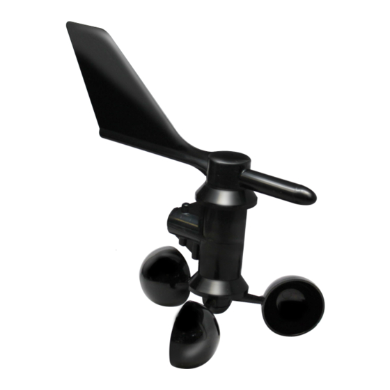
1 INTRODUCTION Anemometer Figure 1: Davis Cup Anemometer Components Installation Hardware Kit Two U-Bolts Four 1/4” Flat washers Four 1/4” Hex Nuts Four 1/4” x 3” Lag Screws One #4 - 40 x 1 1/4” Pan Head Screw One #4 Flat Washer... -
Page 6: Seller's Liability
Anemometer 1 INTRODUCTION Seller’s Liability Seller warrants new equipment of its own manufacture against de- fective workmanship and materials for a period of one year from the date of receipt of equipment. Note: We do not consider the results of ordinary wear and tear, neglect, misuse, accident as defects. -
Page 7: About The Davis Cup Anemometer
2 ABOUT THE DAVIS CUP ANEMOMETER Anemometer About the Davis Cup Anemometer The anemometer enables you to measure and display wind-related conditions such as wind speed and wind direction with your Em50 or Em50R logger. Specifications Wind Direction Display Resolution: 16 points (22.5 ) on compass rose, 1 in... -
Page 8: Assembling The Anemometer
Anemometer 2 ABOUT THE DAVIS CUP ANEMOMETER Speed The Em50 integrates wind speed pulses for one minute. The highest one-minute count in each measurement interval becomes the value for the gusts data. The average of the one-minute counts becomes the average speed for each measurement interval. - Page 9 2 ABOUT THE DAVIS CUP ANEMOMETER Anemometer 2. Push the wind cups onto the smaller of the two stainless steel shafts. Figure 3: Attaching wind Cups to the Anemometer 3. Slide the wind cups as far up the shaft as possible.
- Page 10 Anemometer 2 ABOUT THE DAVIS CUP ANEMOMETER 4. Spin the wind cups. 5. Scan ports of the logger with ECH2O Utility. You should see revolutions and direction. 6. Note the direction reading of the anemometer. 7. Grab the wind vane and twist about half a turn.
-
Page 11: Anemometer Installation
3 ANEMOMETER INSTALLATION Anemometer Anemometer Installation Choosing the Best Location Use the following guidelines to determine the best location for your anemometer. 1. Install the anemometer in a location where wind flow is unob- structed by trees and nearby buildings. For instance, mount the anemometer to an antenna mast, wooden post, or metal pipe. - Page 12 7. If you are not certain about how to ground your installation, consult a qualified professional for national and local codes. Note: If you use the Davis Cup Anemometer in an area subject to frequent thunderstorms, install a lightning rod nearby to reduce the risk of damage.
- Page 13 3 ANEMOMETER INSTALLATION Anemometer Installing on Antenna Mast or Metal Pipe 1. U-bolts work best with an antenna mast or pipe with outside diameter of 7/8” to 1 1/4” (22 to 32 mm). 2. Hold the anemometer base against the pipe and insert the two U-bolts through the back of the base so that the U-bolts wrap around the pipe.
- Page 14 Anemometer 3 ANEMOMETER INSTALLATION 2. Guide the anemometer cable through the slot as you insert the arm. 3. Insert the pan head screw into one of the holes in the base and slide it through the arm. 4. Secure the pan head screw using the flat washer, lock washer, and hex nut as shown.
- Page 15 3 ANEMOMETER INSTALLATION Anemometer Figure 8: Installing Wind Vane Securing the Cable To prevent fraying or cutting the anemometer cable where it is ex- posed to weather, it is very important to secure it so it does not whip about in the wind. Use cable clips or weather resistant cable ties to secure the cable.
-
Page 16: Troubleshooting
Anemometer 4 TROUBLESHOOTING Troubleshooting Your anemometer does not require any regular maintenance. Do not attempt to lubricate the wind cup shaft and bearings or the wind vane shaft. Natural or synthetic lubricants will inhibit the normal operation of the anemometer. Troubleshooting While your anemometer is designed to provide years of trouble-free operation, occasionally problems may arise. - Page 17 4 TROUBLESHOOTING Anemometer Try dropping the wind cups approximately 1/16” to 1/8” (1.5 to 3 mm) lower on the mounting shaft. Use the included Allen wrench to loosen and tighten the wind cup assembly. If you still do not get a reading, the problem is with the anemometer. Contact Decagon Devices for return authorization.
-
Page 18: Declaration Of Conformity
Model Number: Year of First Manufacture: 2005 This is to certify that the Davis Cup Anemometer, manufactured by Davis Instruments., a corporation based in Hayward, California, USA meets or exceeds the standards for CE compliance as per the Council Directives noted above. This anemometer has been adapted to work with Decagon Devices ECH2O System and is based on the Standard Anemometer manufactured by Davis Instruments. - Page 19 Index CE Compliance, 15 Contact Information, 1 Declaration of Conformity, 15 Email, 1 Seller’s Liability, 3 Sensor Components, 2 Specifications, 4 Troubleshooting Quick Guide, 13 Warranty, 2...
Need help?
Do you have a question about the Cup Anemometer and is the answer not in the manual?
Questions and answers