Advertisement
Quick Links
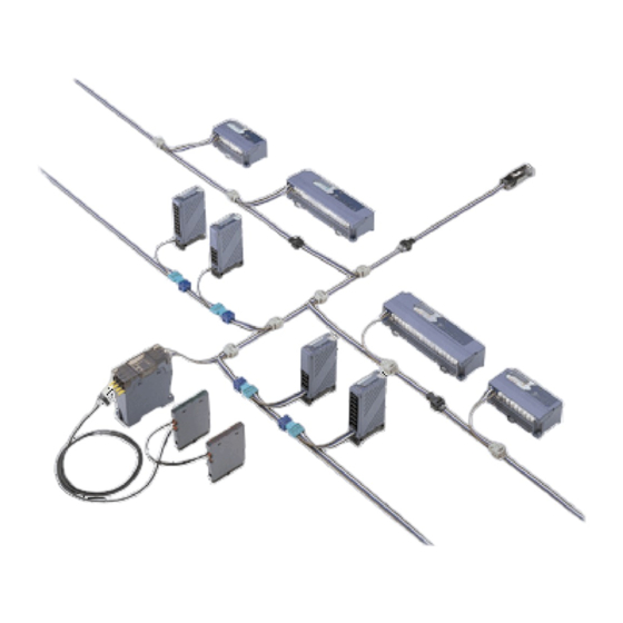
Flexible Wire-saving System S-LINK V
S-LINK V Control Module SL-VMC1
Thank you very much for purchasing Panasonic products.
Please read this Instruction Manual carefully and thoroughly for the correct
and optimum use of this product.
Kindly keep this manual in a convenient place for quick reference.
● Never use this product in a device for personnel protection.
● In case of using devices for personnel protection, use products which
meet laws and standards, such as OSHA, ANSI or IEC etc., for person-
nel protection applicable in each region or country.
● Before touching this product, remove any electrostatic charge that may
be present on your body. There is a danger of this product getting dam-
aged due to the electrostatic charge.
● For details of this product, refer to "Product Specifications" of the product.
For the "Product Specifications" of this product, contact our nearest
sales office.
● Please refer to the "S-LINK V User's Manual" for details of the entire
S-LINK V system.
1
SPECIFICATIONS
Description
Item
Model No.
Supply voltage
(Note 1)
Current consumption
Transmission speed
A mode: 110kbps, B mode: 27.5kbps, C mode: 6.9kbps
Connection method
"T" branch connection or multi-drop connection
Max. 512 points (Using DIP switches, in increments / decre-
I/O points
ments of 32 points is also possible.)
Connectable nodes
Transmission distance A mode: max. 50m, B mode: max. 200m, C mode: max. 800m
Total cable length
A mode: 100m or less, B mode: 400m or less, C mode: 1,600m or less
Exclusive 4-core flat cable (0.5mm
Suitable
4-core VCTF cable (non-shield) conductor cross section of
transmission cable
0.3 to 2.0mm
Address occupation:
256 bytes (including area not used) from the specified address
Specifications for
Address specification:
CPU side
Specified by the CS (chip selection signal) using the external logic
Data bus width: 8 bits
Interruption function
When the input is changed, or when an error occurs
(Note 3)
[Validity (valid or invalid) of interruption can be set.]
Ambient temperature
0 to +55°C (No dew condensation), Storage: -20 to +70°C
(Note 4)
Ambient humidity
(Note 4)
Weight
Accessory
Parts kit: 1 set (refer to "
Notes: 1) 24V DC and 5V DC are insulated.
2) The current consumption value is the total of the maximum current value (D-G line
only) supplied to the S-LINK V I/O units and the current consumption value of the
S-LINK V control module.
3) Validity (valid or invalid) of input interruption can be set for every point. The inter-
ruption condition (ON → OFF or OFF → ON), however, should be set in units of
32 points. If the input change interruption signal and the error occurrence interrup-
tion signal are output at the same time, the priority will be given to the error occur-
rence interruption signal.
4) Values of control module single body are shown in these areas. To mount this
product on your device, these values may be subject to change so that the values
can be optimum for both the control module and your device.
INSTRUCTION MANUAL
MJE-SLVMC1 No.0060-14V
S-LINK V control module
SL-VMC1
[S-LINK V system side] 24V DC
+10
-5
[Control module side] 5V DC±5%
[24V DC] 60mA or less (Note 2)
[5V DC] 200mA or less
Max. 256 nodes
2
) or
2
20 to 85% RH, Storage: 20 to 85% RH
Approx. 20g
PARTS KIT.")
2
PARTS KIT
● The following parts are attached to this product. Make sure to check
those before use.
Common mode filter: 1 pc.
Ceramic capacitor (blue): 2 pcs.
Poly switch: 2 pcs.
3
CAUTIONS
In case of designing a board, take care of the bottom of this product that is
the area of being prohibited from mounting parts, mounting of the parts kit,
and pattern width.
● This product has been developed / produced for industrial use only.
● This product is not equipped with a short-circuit protection circuit. Use a
power supply having a short-circuit protection function (e.g. fuse, etc.).
● Verify that the supply voltage variation is within the rating. Also, check
%
the voltage variation at the end terminal of the transmission route, since
voltage drop occurs depending on the diameter or the length of the
transmission cable.
● If power is supplied from a commercial switching regulator, ensure that
the frame ground (F.G.) terminal of the power supply is connected to an
actual ground.
● Do not use during the initial transient time after the power supply is
switched ON. Furthermore, transmission is not possible when the system is
in Busy state (during switching ON of the power supply or system setting.)
● Make sure to use an isolation transformer for the DC power supply. If an
auto-transformer (single winding transformer) is used, this product or the
power supply may get damaged.
● In case a surge is generated in the power supply used, connect a surge
absorber to the supply and absorb the surge.
● Solder terminals at 260°C or less within 10 seconds.
● Do not run the wires together with high-voltage lines or power lines or put
them in the same raceway. This can cause malfunction due to induction.
● Make sure to carry out wiring in the power supply OFF condition.
● Take care that wrong wiring will damage the product.
● In order to reduce noise, make the wiring as short as possible.
● In case noise generating equipment (switching regulator, inverter motor,
etc.) is used in the vicinity of this product, connect the frame ground (F.G.)
terminal of the equipment to an actual ground.
● This product does not have a dust-proof or water-proof construction. Do
not use it in a place having excessive vapor, dust, etc.
● Take care that the product does not come in contact with water, chemi-
cals or organic solvents, such as thinner, etc. Furthermore, do not use it
in an environment having corrosive gas.
● Do not use the product in places where the ambient temperature or the
humidity exceeds the specifications.
● Do not touch this product while operation since there are some parts
whose temperatures become high.
Diode: 1 pc.
Surge absorber (black): 1 pc.
Aluminum electrolytic capacitor:
1 pc.
Advertisement

Related Manuals for Panasonic S-LINK V SL-VMC1


Summary of Contents for Panasonic S-LINK V SL-VMC1
- Page 1 Common mode filter: 1 pc. Diode: 1 pc. S-LINK V Control Module SL-VMC1 MJE-SLVMC1 No.0060-14V Thank you very much for purchasing Panasonic products. Ceramic capacitor (blue): 2 pcs. Surge absorber (black): 1 pc. Please read this Instruction Manual carefully and thoroughly for the correct and optimum use of this product.
- Page 2 G of S-LINK V side and operation power of 0V http://panasonic.net/id/pidsx/global Overseas Sales Division (Head Office) 2431-1 Ushiyama-cho, Kasugai-shi, Aichi, 486-0901, Japan Phone: +81-568-33-7861 FAX: +81-568-33-8591 For sales network, please visit our website. PRINTED IN JAPAN © Panasonic Industrial Devices SUNX Co., Ltd. 2017...