Table of Contents
Advertisement
Advertisement
Table of Contents

Related Manuals for insys icom GSM small 2.0

Summary of Contents for insys icom GSM small 2.0
- Page 1 INSYS GSM small 2.0...
- Page 3 Copyright © February 12 INSYS MICROELECTRONICS GmbH Any duplication of this manual is prohibited. All rights on this documentation and the devices are with INSYS MICROELECTRONICS GmbH Regensburg. Trademarks The use of a trademark not shown below is not an indication that it is freely avail- able for use.
- Page 4 Content Preface.....................7 Defects Liability Terms ..................7 Marking of Warnings and Notes................8 1.2.1 Symbols and Key Words ................8 Symbols and the Formatting in this Manual ............9 Safety.....................10 Usage According to the Regulations ..............10 Permissible Technical Limits................11 Responsibilities of the Operator................11 Qualification of the Personnel................11 Instructions for Transport and Storage ..............11 Markings on the Product ..................12...
-
Page 5: Table Of Contents
Contents Functions ....................35 11.1 Entering the PIN of the SIM Card ................35 11.2 Insert and Remove SIM Card................36 11.3 Checking the Status of the GSM Login..............38 11.4 Checking the GSM Signal Quality................39 11.5 Automatic baud rate detection ................40 11.5.1 Serial Connection ................... 40 11.5.2 Phone connection .................. - Page 6 Content Maintenance, Repair and Troubleshooting..........83 16.1 Maintenance......................83 16.2 Troubleshooting....................83 16.3 Repair ........................83 Waste Disposal ..................84 17.1 Repurchasing of Legacy Systems................84 Declaration of Conformity ..............85 Tables and Diagrams................86 19.1 List of Tables .......................86 19.2 List of Diagrams ....................86 Index......................87 Feb-12...
- Page 7 INSYS GSM small 2.0 Preface Preface This manual allows for the safe and efficient use of the product. The manual is part of the product and must always be stored accessible for installation, commission- ing and operating personnel. Defects Liability Terms...
- Page 8 Preface INSYS GSM small 2.0 Marking of Warnings and Notes 1.2.1 Symbols and Key Words Danger! Risk of severe or fatal injury One of these symbols in conjunction with the key word Danger indicates an imminent danger. It will cause death or severe injuries if not avoided.
- Page 9 INSYS GSM small 2.0 Preface Symbols and the Formatting in this Manual This section describes the definition, formatting and symbols used in this manual. The various symbols are meant to help you read and find the information relevant to you. The following text is structured like a typical operating instruction of this manual.
- Page 10 Safety INSYS GSM small 2.0 Safety The Safety section provides an overview about the safety instructions, which must be observed for the operation of the product. The product is constructed according to the currently valid state-of-the-art technol- ogy and reliable in operation. It has been checked and left the factory in flawless condition concerning safety.
- Page 11 INSYS GSM small 2.0 Safety Permissible Technical Limits The product is only intended for the use within the permissible technical limits specified in the data sheets. The following permissible limits must be observed: The ambient temperature limits must not be fallen below or ex- ceeded.
- Page 12 Safety INSYS GSM small 2.0 Markings on the Product The identification plate of the product is either a print or a label on a face of the product. Amongst other things, it contains the following markings, which are ex- plained in detail here.
- Page 13 INSYS GSM small 2.0 Safety Safety Instructions for Electrical Installation The electrical connection must only be made by authorised expert personnel ac- cording to the wiring diagrams. The notes to the electrical connection in the manual must be observed. Otherwise, the protection category might be affected.
- Page 14 Safety INSYS GSM small 2.0 Caution! Overvoltage and voltage peaks from the mains supply! Fire hazard and damage of the product due to overvoltage. Install suitable overvoltage protection. Caution! Damage due to chemicals! Ketones and chlorinated hydrocarbons dissolve the plastic housing and damage the surface of the device.
- Page 15 Scope of Delivery Scope of Delivery The scope of delivery for the INSYS GSM small 2.0 includes all accessories listed below. Please check if all accessories are included in the box. If a part is missing or damaged, please contact your distributor.
- Page 16 Technical Data INSYS GSM small 2.0 Technical Data Physical Features All specified data was measured with nominal input voltage, at full load, and an ambient temperature of 25 °C. The limit value tolerances are subject to the usual variations. Physical Feature...
- Page 17 - Cell Broadcast (CB) Quad band GSM frequen- 850, 900, 1800, 1900 MHz cies The INSYS GSM small 2.0 is enabled for all bands by default. A restriction to the frequency bands 900 and 1800 MHz is configured using the com- mand AT^SCFG="Radio/Band",3,3.
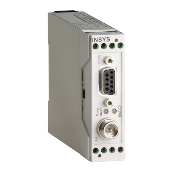
- Page 18 Display and Control Elements INSYS GSM small 2.0 Display and Control Elements Display Elements Figure 1: LEDs on the front panel Position Description Power / RX/TX LED Net / DCD LED Table 3: Description of the LEDs on the front panel The left LED (Power / RX/TX) indicates the status of the power supply as well as data communication.
- Page 19 INSYS GSM small 2.0 Display and Control Elements Colour Blinking: Flashing: green - - - - - - Power supply is present Power Data is being trans- Power / supply is ferred; LED Device is in Power- orange - - -...
- Page 20 Display and Control Elements INSYS GSM small 2.0 Control Elements Figure 2: Control elements on the bottom of the device Position Description SIM card holder eject key SIM card holder insert Table 5: Description of the control elements on the bottom of the device...
- Page 21 INSYS GSM small 2.0 Connections Connections Front Panel Connections Figure 3: Connections on the front panel of the device Position Description Serial interface (RS232 socket) Antenna connection (FME socket) Table 6: Description of the connections on the front panel of the device...
- Page 22 Connections INSYS GSM small 2.0 Terminal Connections on the Top Figure 4: Connections on the top of the device Terminal Description Description Power supply 10V - 48V DC 10..48 VDC (voltage figures are limit values without tolerances) Ground Reset Reset input...
- Page 23 INSYS GSM small 2.0 Connections Pin Assignment of the Serial Interface Figure 6: 9-pin D-Sub socket at the device Signal Description Data Carrier Detect Receive Data Transmit Data Data Terminal Ready Ground Data Set Ready Request To Send Clear To Send...
- Page 24 INSYS GSM small 2.0 exceed a certain level. An application can also prompt the INSYS GSM small 2.0 via a control line to interrupt the data flow. As an alternative, the INSYS GSM small 2.0 can control the data flow via XOFF/XON characters in the data stream.
- Page 25 Function Overview Automatic reset The INSYS GSM small 2.0 can make an automatic reset after a certain number of operating hours. The reset ensures a regular logout and re- login into the GSM network and thus a safe availability in the GSM network.
- Page 26 INSYS GSM small 2.0 Mounting This section describes how to mount the INSYS GSM small 2.0 to a DIN rail, connect the power supply and uninstall it again. Observe the instructions in the "Safety" section of this manual, in particular the "Safety Instructions for Electrical Installation"...
- Page 27 Position the device at the DIN rail as seen in the following diagram. There are two snap-in hooks at the upper and lower edge of the DIN rail groove of INSYS GSM small 2.0. Hook the upper one into place behind the upper edge of the DIN rail.
- Page 28 The INSYS GSM small 2.0 is disconnected from the power supply. Uninstalling the device from the DIN rail How to uninstall the INSYS GSM small 2.0 from a DIN rail in a switch cabi- net: You will need a Phillips screwdriver with a 4.5 mm blade.
- Page 29 The plastic spring of the snap-in hook is stretched. While you hold the plastic spring apart with the lower snap-in hooks, pull the INSYS GSM small 2.0 away from the DIN rail. Un-hook the INSYS GSM small 2.0 and take it off perpendicularly to the DIN rail. ...
- Page 30 Initial Operation This section describes how to put the INSYS GSM small 2.0 in operation, i.e. how to connect the INSYS GSM small 2.0 to a PC and test the serial commu- nication. Connecting the INSYS GSM small 2.0 to a PC How to connect the INSYS GSM small 2.0 to a PC via the serial interface.
- Page 31 The baud rate and protocol settings in the terminal program must cor- respond with the settings of the INSYS G SM small 2.0. The INSYS GSM small 2.0 is configured to 115.200 baud, 8 data bits, 1 stop bit, and no parity (8N1) by default. Enter AT into your terminal p rogram and confirm with the Enter key.
- Page 32 This section describes the basic procedures to operate and configure a INSYS GSM small 2.0. There are several methods to operate and configure the INSYS GSM small 2.0. In general, the INSYS GSM small 2.0 is configured and operated via AT commands.
- Page 33 Reference". Save your entries with AT&W. Not all configurations at the INSYS GSM small 2.0 need to be saved actively by entering AT&W. Some settings are automatically sav immediately. We still recommend sending the command AT&W to the INSYS GSM small 2.0 as your last configuration s...
- Page 34 Then, click on the Send settings button in the field on the right. A progress bar appears above the button. Now, the settings made are transmitted to the INSYS GSM small 2.0 and stored there. A message window is displayed that requests to switch the INSYS GSM small 2.0 off and on again or perform a hardware reset.
-
Page 35: Functions
INSYS GSM small 2.0 without inserting the SIM card. If the SIM card re- quires no PIN, you don’t have to store a PIN in the INSYS GSM small 2.0. If you enter a PIN, the PIN will be transferred to the SIM card with each login attempt. -
Page 36: Insert And Remove Sim Card
11.2 Insert and Remove SIM Card A SIM card must be inserted that your INSYS GSM small 2.0 is able to log into the GSM network and transmit data. Moreover, the INSYS GSM small 2.0 must know the PIN of the SIM card. - Page 37 Functions Push the SIM card holder with the inserted SIM card with the con- tacts of the SIM card facing left into the INSYS GSM small 2.0. The SIM card can now be used by the INSYS GSM small 2.0.
-
Page 38: Checking The Status Of The Gsm Login
You can query the login status for test purposes. Then, you can de- termine, whether the INSYS GSM small 2.0 is currently logged in or not, a network search is currently performed, a login has been rejected by the GSM network, or the device is logged in into a foreign network via roaming. -
Page 39: Checking The Gsm Signal Quality
11.4 Checking the GSM Signal Quality You can check the signal field strength at the location of the INSYS GSM small 2.0. The signal quality has an essential influence on the data transmission speed. If the signal field strength is too low, the transmission speed can drop severely or the connection can be terminated at all. -
Page 40: Automatic Baud Rate Detection
If "0" is entered here for <n>, the automatic baud rate detection is active. The INSYS GSM small 2.0 must be configured with the baud rate, which is used to operate the application at a later time, as the INSYS GSM small 2.0 will always use the last known functioning configuration of its inter-... -
Page 41: Phone Connection
The connection speed can be set through the phone line via the connection protocol. If nothing is defined, the INSYS GSM small 2.0 will automatically try to determine the optimum connection parameters. -
Page 42: Data Flow Control (Handshake)
When the buffer is emptied sufficiently for the INSYS GSM small 2.0 to be able to receive data again, the CTS line is set to "high". Reversely, the application can also indicate to the INSYS GSM small 2.0 to hold the data flow. - Page 43 INSYS GSM small 2.0 Functions XOFF characters would disturb the operation. Configuration with HSComm Select the type of data flow control or switch it off completely on the "Serial interface" tab in the "Handshake" panel. Configuration with AT commands In order to enable data flow control and set...
-
Page 44: Establishing Or Accepting A Csd Data Connection
2.0 synchronises with the called modem and opens a data connection with the transmission speed allowed by the GSM network. This is usually 9600 bit/s. The speed, which is set at the serial interface of the INSYS GSM small 2.0 at the time of connection establishment, will not be changed. -
Page 45: Establishing A Ppp Data Connection
In order to change from command mode to normal data transmission again, use the com- mand In order to terminate a connection and cause the INSYS GSM small 2.0 to hang up, use the com- mand Terminating the connection via DTR Drop might also be possible. -
Page 46: Automatic Call Acceptance
INSYS GSM small 2.0 11.9 Automatic call acceptance The automatic call acceptance enables the INSYS GSM small 2.0 to accept each call after the configured number of ring tones. Configuration with HSComm In order to enable automatic call acceptance, check on the “Basic set- tings”... -
Page 47: Sending An Sms Manually
INSYS GSM small 2.0 Functions 11.10 Sending an SMS Manually It is possible to send an SMS manually with the INSYS GSM small 2.0. Configuration with HSComm A manually triggered SMS dispatch with the HSComm software is not possible. Configuration with AT commands... -
Page 48: Automatic Execution Of At Commands
If all functions are configured in the configuration software HSComm, all memory locations are used. The settings of this command are stored using the command AT^SMSO. This command shuts down the INSYS GSM small 2.0. It can be restarted by briefly disconnecting the power supply. -
Page 49: Automated Pin Entry And Login After Restart
After the configured time has expired fol- Exec“,1,1,0,0,“AT+COPS lowing a restart, the response at the serial =0“ interface is ^SCFG: “Auto- Then, the INSYS GSM small 2.0 is logged in Exec“,1,1,1,0,“AT+CPIN =<PIN>“ into the GSM network. AT^SCFG=“AutoExec“,0,1 In order to disable the automated login into the GSM network, use the command AT^SCFG=“AutoExec“,0,1... -
Page 50: Automatic Reset
11.11.2 Automatic reset In order to prevent a faulty login state of the INSYS GSM small 2.0 in case of infra- structure changes of the GSM network (software updates of the databases, tempo- rary network extensions e.g. for trade fairs), the device should be logged out and in again or shut down and restarted and initialised periodically. -
Page 51: Alarm Via Dtr Control Line
Functions 11.11.3 Alarm via DTR Control Line The INSYS GSM small 2.0 can send a message or establish a data connection upon activating the DTR control line of the serial interface (e.g. by opening a COM port at a PC). - Page 52 Functions INSYS GSM small 2.0 In order to configure an SMS message, en- ter the destination number using the com- mand AT+CMGW=<“number“> Finish the destination number entry in in- ternational format in quotation marks with the Enter key <CR>. Following the prompt >, enter the text of >SMS Text...
- Page 53 Functions 11.11.3.2 Establishing a Data Connection via DTR Activation The INSYS GSM small 2.0 can establish a data connection when activating the DTR control line of the serial interface. Configuration with HSComm In order to establish a data connection upon DTR activation, select on the "Serial interface"...
-
Page 54: Configuration Of Energy Conservation Modes And Real-Time Clock
11.12.1.1 Time / Date The real-time clock (RTC) of the INSYS GSM small 2.0 has no buffer and will be re- set to "02/01/01,00:00:00" if the power supply is disconnected. The RTC takes 2 seconds for initialisation after a restart (reset or power-up). Therefore, we rec- ommend to wait 2 seconds for the message ^SYSSTART before executing the com- mands AT+CCLK and AT+CALA. - Page 55 <yy/mm/dd,hh:mm:ss> and <text> with the text (max. 16 characters), which is to be issued via the serial interface at alarm time. If the INSYS GSM small 2.0 is in normal +CALA: <text> mode at alarm time, it displays the mes- sage If the INSYS GSM small 2.0 is in Power-...
-
Page 56: Change Between The Energy Conservation Modes
Functions INSYS GSM small 2.0 11.12.2 Change Between the Energy Conservation Modes The following is a short overview of the possible changes from and into the differ- ent energy conservation modes. The possibilities in sleep mode depend on the set- ting of the sleep mode with AT+CFUN. -
Page 57: Sleep Modes
11.12.3.2 Non-Cyclic Sleep Mode The serial interface is disabled in this sleep mode. Every "wake-up event", which is possible in this mode, (except AT commands) causes the INSYS GSM small 2.0 to change into normal mode. Configuration with HSComm A configuration of this function using the HSComm software is not pos- sible. - Page 58 The polling cycle of the serial interface is coupled with the so-called paging re- quests of the INSYS GSM small 2.0 to the GSM base station and is between 0.47 and 2.12 seconds. The CTS line becomes active for 4.6 ms with each polling; further 4.6 ms activity of the serial interface of the INSYS GSM small 2.0 follow (ready to receive).
-
Page 59: Power-Down Mode
Table 11: Energy conservation modes – exiting the sleep mode 11.12.4 Power-Down Mode The INSYS GSM small 2.0 is not registered in the GSM network in power-down mode. The GSM engine disables itself and only the real-time clock (RTC) remains active. - Page 60 RTC (AT+CALA) can be used to change the INSYS GSM small 2.0 from power-down into RTC alarm mode. If a configured RTC alarm occurs during the INSYS GSM small 2.0 is in power- down mode, the RTC alarm mode is entered with the message: ^SYSSTART ALARM MODE [+CALA: <text>]...
-
Page 61: Shutdown Mode
The INSYS GSM small 2.0 can be operated at a programmable logic controller. Set- tings recommended by INSYS for a INSYS GSM small 2.0, which is used at the PC to communicate with the PLCs, are available for certain controllers. The respective configuration files can be found under http://www.insys-tec.de/en/en/plc/ or in the... -
Page 62: Using Ussd Codes
GSM small 2.0 for example, use the com- mand 11.15 Resetting the Device The INSYS GSM small 2.0 can be reset in several ways: by briefly cutting off the supply voltage, by connecting the reset input with GND, using an AT command, or using the HSComm software. -
Page 63: At Command Reference
The AT commands can only be entered locally via the serial interface, if the INSYS GSM small 2.0 is in offline state (no active data connection) or in online command mode (interrupted data connection). The most important commands are listed in this document. -
Page 64: Short Description At Commands
AT Command Reference INSYS GSM small 2.0 Each command is acknowledged with a response according to V.250 (configura- tion with ATV): Response Code Type Meaning final Command executed, no error CONNECT final Connection established, if parameter setting CONNECT[<text>] final Connection established, if parameter setting X>0 <text>: e.g. -
Page 65: At Commands According To V.250
AT Commands According to V.250 Command Description Answer mode (manual call acceptance for incoming CSD connection) The INSYS GSM small 2.0 changes to answer mode. An incoming CSD connection will be accepted. Configuring the function of the DCD control line AT&C<n>... - Page 66 AT Command Reference INSYS GSM small 2.0 Command Description Querying the data format of the serial interface AT+ICF=<format> 8 data bits, no parity bit, 2 stop bits [,<parity>] <format> 8 data bits, 1 parity bit, 1 stop bit 8 data bits, no parity bit, 1 stop bit 7 data bits, 1 parity bit, 1 stop bit <parity>...
- Page 67 INSYS GSM small 2.0 AT Command Reference Command Description Configuring the baud rate of the serial interface AT+IPR=<baud> Note: It is not possible to change the baud rate for the i-modul UMTS 4.1 basic. The baud rate is fixed to 115200 bps here.
- Page 68 AT Command Reference INSYS GSM small 2.0 Command Description Reading/writing the S registers ATS<n> Some S registers can only be modified in certain limits. The modem still reports OK, although the value has not changed as specified. Some regis- ters can only be read. We recommend therefore to check the results after each write attempt, using the ATSn? command.
-
Page 69: At Commands For Gsm Connections
INSYS GSM small 2.0 AT Command Reference Command Description CONNECT response format and connection monitoring ATX<n> <n> Numerical response for CONNECT, no dial tone detection, no busy signal detection Text response for CONNECT, no dial tone detection, no busy signal detection... - Page 70 AT Command Reference INSYS GSM small 2.0 Command Description Automatic (default) <oper>,<AcT>] AT+COPS=0 Manual selection <oper> AT+COPS=1 Logout from GSM network AT+COPS=2 Manual selection <oper> - if not available, AT+COPS=4 automatic selection Alphanumerical information (up to 16 digits) for <format>...
-
Page 71: At Commands For Sms
INSYS GSM small 2.0 AT Command Reference Command Description Displaying the registration state (network state) AT+CREG? Response: <n>,<stat> Not logged in, no GSM network search <stat> Logged in with the standard provider Not logged in, GSM network search Refused Logged in, roaming... -
Page 72: At Commands For Gprs Connections
AT Command Reference INSYS GSM small 2.0 Command Description Sending an SMS message AT+CMGS=<no> <CR><text> Phone number <no> <Ctrl-Z> Enter/carriage return key <CR> Text of the SMS message <text> Press CTRL and Z (1Ah) <Ctrl-Z> The phone number entry is completed with <CR>, the actual text with <Ctrl-Z>. - Page 73 INSYS GSM small 2.0 AT Command Reference Command Description Enable/disable PDP context AT+CGACT=[<stat e>[,<cid>[,<cid PDP context indicated with <cid> disabled (default) <state> >[,...]]]] PDP context indicated with <cid> enabled Index of a PDP context (refer to AT+CGDCONT) to be enabled / <cid>...
- Page 74 AT Command Reference INSYS GSM small 2.0 Command Description service commitments shall be maintained ahead of priority classes 2 and 3. Normal priority; service commitments shall be maintained ahead of priority class 3. Low priority; service commitments shall be maintained.
- Page 75 INSYS GSM small 2.0 AT Command Reference Command Description 2000 bytes/hour (~ 4.4 bps) 5000 bytes/hour (~ 11.1 bps) 10,000 bytes/hour (~ 22 bps) 20,000 bytes/hour (~ 44 bps) 50,000 bytes/hour (~ 111 bps) 100,000 bytes/hour (~ 0.22 kbps) 11 200,000 bytes/hour (~ 0.44 kbps) 12 500,000 bytes/hour (~ 1.11 kbps)
- Page 76 AT Command Reference INSYS GSM small 2.0 Command Description Configuring the GPRS network registration state display AT+CGREG=<n> Unsolicited result codes for GPRS network registration state <n> No unsolicited result codes Display unsolicited result codes (Only with change of registration state) After entering the command AT+CGREG? or with unsolicited result codes activated <n>...
- Page 77 INSYS GSM small 2.0 AT Command Reference Command Description Displaying GPRS-specific cell information in a single line AT^SMONG Response: "GPRS Monitor", below the column titles and # cell # and in the bottom line the cell data (in one line), e.g.:...
-
Page 78: At Commands For Energy Conservation Functions
CYCLIC SLEEP mode 7 CYCLIC SLEEP mode 8 No importance <rst> The GSM engine of the INSYS GSM small 2.0 performs a reset; the value of <fun> is not important here, it only serves as placeholder Putting GSM engine into Power-Down mode... -
Page 79: At Commands For Time Functions
INSYS GSM small 2.0 AT Command Reference 12.2.6 AT Commands for Time Functions Command Description Displaying current time and date AT+CCLK? Configuring time and date AT+CCLK=<time> Refer to the section Energy Conservation Modes and Real-Time Clock for details. Displaying alarm time settings... -
Page 80: Gsm Service Center Numbers
GSM Service Center Numbers INSYS GSM small 2.0 13 GSM Service Center Numbers The following is an overview of the most important mobile phone providers in Germany, Austria and Switzerland. All information is without guarantee of correct- ness and completeness. The specified numbers may only be valid for certain con- tracts with the mobile phone provider. -
Page 81: Apn Access Data
INSYS GSM small 2.0 APN Access Data 14 APN Access Data In order to access a GPRS/EDGE/UMTS network, you need a valid GPRS/EDGE/UMTS card contract and the following information from your provider: APN (Access Point Name, access address of the provider) ... -
Page 82: Network Provider Codes
Network Provider Codes INSYS GSM small 2.0 Network Provider Codes Codes and names of the network providers (GSM Location Area Identification Number) for the GSM modules in alphabetic order for the command AT+COPS. The following table may be output with the command AT^SPLM. -
Page 83: Maintenance, Repair And Troubleshooting
16.3 Repair Send defect devices with detailed failure description to the source of supply of your device. If you have purchased the device directly from INSYS icom, send the device to: INSYS MICROELECTRONICS GmbH, Waffnergasse 8, 93047 Regensburg. Caution! Short circuits and damage due to improper repairs and modifications as well as opening of products. -
Page 84: Waste Disposal
Waste Disposal INSYS GSM small 2.0 Waste Disposal 17.1 Repurchasing of Legacy Systems According to the new WEEE guidelines, the repurchasing and recycling of legacy systems for our clients is regulated as follows: Please send those legacy systems to the following address, carriage prepaid:... -
Page 85: Declaration Of Conformity
INSYS GSM small 2.0 Declaration of Conformity Declaration of Conformity This device complies with the requirements set out in the Council Directive on the Approximation of the Laws of the Member States relating to Electromagnetic Compatibility 2004/108/EC and the Council Directive relating to Low Voltage 2006/95/EC as well as the Council Directive R&TTE 1999/5/EC. -
Page 86: Tables And Diagrams
Tables and Diagrams INSYS GSM small 2.0 Tables and Diagrams 19.1 List of Tables Table 1: Physical Features ..................16 Table 2: Technological Features................17 Table 3: Description of the LEDs on the front panel ..........18 Table 4: Meaning of the LED displays..............19 Table 5: Description of the control elements on the bottom of the device ..... -
Page 87: Index
INSYS GSM small 2.0 Index Index Accessories ........15 General safety instructions....13 Additional information....... 9 GPRS ..........25 Alternative results ......9 Ground ..........22 Ambient temperature ...... 16 GSM network ......38, 44 Antenna connection ......21 Handshake ........42 AT command........ - Page 88 Index INSYS GSM small 2.0 Real time clock........ 54 SIM card holder....... 20 Recycling......... 84 SIM card holder - eject key ..... 20 Removal .......... 26 SIM card holder eject key..36, 37 Remove SIM card......37 SIM PIN ........... 36 Repair ........
Need help?
Do you have a question about the GSM small 2.0 and is the answer not in the manual?
Questions and answers