Table of Contents
Advertisement
Quick Links
Advertisement
Table of Contents

Related Manuals for MICRO-EPSILON C-Box/2A


Summary of Contents for MICRO-EPSILON C-Box/2A
- Page 1 Operating Instructions C-Box/2A MICRO-EPSILON MESSTECHNIK GmbH & Co. KG Koenigbacher Str. 15 · 94496 Ortenburg / Germany Tel. +49 (0) 8542 / 168-0 · Fax +49 (0) 8542 / 168-90 info@micro-epsilon.com · www.micro-epsilon.com Your local contact: www.micro-epsilon.com/contact/worldwide/...
- Page 2 Controller for ILD 1420, ILD 1750, ILD 1900, ILD 2300 and confocalDT IFC2422 series MICRO-EPSILON MESSTECHNIK GmbH & Co. KG Koenigbacher Str. 15 94496 Ortenburg / Germany Tel. +49 (0) 8542 / 168-0 Fax +49 (0) 8542 / 168-90 info@micro-epsilon.com...
-
Page 3: Table Of Contents
Software Update ............................19 Operation Using Ethernet ..........................20 5.4.1 Requirements ..........................20 5.4.2 Access via Ethernet ........................20 5.4.3 Measured Value Presentation with Web Browser ................ 26 Programming Using ASCII Commands ......................29 Timing Behavior, Flow of Measurement Values .................... 29 C-Box/2A... - Page 4 6.7.3 Load Settings ..........................52 6.7.4 Manage Settings on PC ....................... 53 6.7.5 Reset ............................. 54 Info ................................. 54 Software Support with MEDAQLib ..................55 Liability for Material Defects ....................56 Service, Repair ........................56 Decommissioning, Disposal ....................56 C-Box/2A...
- Page 5 Interfaces ............................71 A 2.3.3.1 Ethernet ........................71 A 2.3.3.2 Setting the Measured Value Server ................71 A 2.3.3.3 Baudrate ........................71 A 2.3.3.4 Find C-Box/2A ......................71 A 2.3.4 Handling of Setups ........................71 A 2.3.4.1 Save Parameter ......................71 A 2.3.4.2 Load Parameter ......................
- Page 6 Outputs ............................90 A 3.2.5 System Settings ..........................92 A 3.3 Tab Measurement ............................93 A 3.3.1 Measurement Configuration ......................93 A 3.3.2 Channel Selection ........................93 A 3.3.3 Auto Zero ............................93 A 3.4 Tab Info ................................94 C-Box/2A...
-
Page 7: Safety
> Damage to or destruction of the controller The supply voltage must not exceed the specified limits. > Damage to or destruction of the controller Avoid shocks and impacts to the controller. > Damage to or destruction of the controller C-Box/2A Page 7... -
Page 8: Notes On Ce Marking
The EU Declaration of Conformity is available to the responsible authorities according to EU Directive, article Intended Use - The C-Box/2A is designed for industrial use in automated manufacturing and machine monitoring. It is used for ƒ processing 2 digital input signals, e. g. thickness measurement ƒ... -
Page 9: Functional Principle, Technical Data
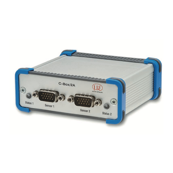
- D/A converter of the digital measurements, output via current and voltage interface The C-Box/2A is installed in a stable aluminium case. Two digital sensors of the same series can be directly connected to the C-Box/2A via RS422. Both sensors are synchronized via the C-Box/2A; the C-Box/2A is the master. -
Page 10: Technical Data
Functional Principle, Technical Data Technical Data Model C-Box/2A - 2 Sensor connectors (HD-Sub, 15-pin), - 2 RS422 interfaces - 1x Ethernet (PC, 100 Mbit/s), - 1x USB 2.0, type B, max. 12 Mbit, - 1 plug-in terminal block 16-pin ƒ External power supply ƒ... - Page 11 Functional Principle, Technical Data Model C-Box/2A - 1 current output per connected sensor ƒ 4 – 20 mA - 1 voltage output per connected sensor; programmable: Analog output ƒ Unipolar 0 – 5 V / Unipolar 0 – 10 V ƒ...
-
Page 12: Delivery
Delivery Model C-Box/2A Operating +5 ... +50 °C (+41 ... +122 °F) Temperature range Storage 0 ... +50 °C (+32 ... +122 °F) Relative air humidity 5 ... 95 %, non-condensing Delivery Unpacking, Included in Delivery C-Box/2A Operating instructions 16-pin. female terminal box (cable clamp) with locking function type Weidmüller B2CF 3.50/16/180 SN BK BX... -
Page 13: Installation And Mounting
Installation and Mounting Dimensional Drawing Pay attention to careful handling during 102.9 (4.05) the installation and operation. C-Box/2A Status 1 Sensor 1 Sensor 2 Status 2 Fig. 1 Dimensions C-Box/2A, dimensions in mm (inches), not to scale C-Box/2A Page 13... -
Page 14: Electrical Connections, Leds
Sensor in measurement mode and within the measurement range Sensor in measurement mode and sensor outside the measurement range Orange Sensor in setup mode (no measurement output) Fig. 3 Description LED (1) for sensor 1 resp. sensor 2 C-Box/2A Page 14... - Page 15 Power on, data output on USB interface active, Orange data communication faulty or disconnected Power on, data output on USB interface active, USB cable not connected or communication disconnected Fig. 5 LED description for power and USB status (3) C-Box/2A Page 15...
-
Page 16: Laser On
Switching can be done with a transistor (for example open collector in an optocoupler) or a relay contact. Laser Connect pin 6 with pin 8 by a jumper. The laser is off unless pin 6 is electrically connected to pin 8. C-Box/2A Page 16... -
Page 17: Operation
PLC, and the power supply in compliance with the connection instructions. After switching on the operating voltage, the C-Box/2A performs an initialization sequence and goes into the measurement operating mode afterwards. The laser operation on optical sensors is only indicated at the sensor by an LED. If no measured values are transmitted, check whether the sensors are switched on and whether a target is in the measuring range of the sensor. - Page 18 Operation If the installation is done properly, you will find C-Box/2A in the device manager, see Fig. 7. Fig. 7 View Device Manager after installing the USB driver C-Box/2A Page 18...
-
Page 19: Software Update
Download the USB driver from the homepage, see 5.2 and unpack it. Start the installation program. Search for the C-Box. Choose the update file. Start the installation. Wait until the installation is complete. Fig. 8 View MICRO-Epsilon Update Sensor C-Box/2A Page 19... -
Page 20: Operation Using Ethernet
C-Box/2A to a network or directly to a PC. The C-Box/2A is delivered as standard with a fixed IP address. If you do not require a static IP address, you can enable DHCP (Dy- namic Host Configuration Protocol) as automatic IP address allocation. The controller will be assigned an IP address by the DHCP server, see 5.4.2. - Page 21 PC uses the following IP address, for example: 169.254.168.1 Interactive web pages for setting the C-Box/2A and peripherals are now shown in the web browser, see Fig. 11 ff. Parallel operation with web browser and ASCII commands is possible; the last setting applies. Do not forget to save.
- Page 22 Operation Fig. 10 sensorTOOL auxiliary program for sensor search sensorTOOL x.x.x program is available online at http://www.micro-epsilon.com/service/download/ software. sensorTOOL x.x.x program searches the available interfaces for connected controllers. C-Box/2A Page 22...
- Page 23 IP address Submit. All settings in the web page are applied immediately in the C-Box/2A after clicking the button The controller is active and supplies measurement values. The currently running measurement can be con- diagram control trolled using the function buttons in the section.
- Page 24 The inputs section shows in blue text the current settings for connected sensors, see 6.3.1. Measurement configuration menu The measurement configuration section shows in blue text the current measurement task, see 6.4.1 and additional process- ing configurations, such as mastering/zeroing and trigger mode. C-Box/2A Page 24...
- Page 25 The system configuration section shows in blue text the cur- rently selected digital interface, see 6.6.1. Data selection menu The data selection section shows in blue text the currently selected data for the Ethernet and USB interfaces, see 6.6.2; that data are required for further processing. C-Box/2A Page 25...
-
Page 26: Measured Value Presentation With Web Browser
Operation 5.4.3 Measured Value Presentation with Web Browser Measurement Start the display of measurement values by using the tab. Fig. 12 Presentation of the measurement and calculation results C-Box/2A Page 26... - Page 27 Auto Zero The check boxes in the window/selection set the selected channel to zero only in the diagram. This setting does not affect the C-Box/2A or connected sensors. Channel Selection The check boxes in the window/selection allow you to specify the channels that you would like displayed in the diagram.
- Page 28 Auto Zero The check boxes in the window/selection set the selected channel to zero only in the diagram. This setting does not affect the C-Box/2A or connected sensors. Autoscale The y-axis can be scaled manually or by using the function.
-
Page 29: Programming Using Ascii Commands
Timing Behavior, Flow of Measurement Values Without triggering, the controller requires 5 cycles to process the C-Box values: The cycle time depends on the C-Box setting and values range from 0.4 to 80 kHz. C-Box/2A Page 29... -
Page 30: Setting Controller Parameters
Setting Controller Parameters Setting Controller Parameters Preparation for Setting the Options You can program the C-Box/2A in various ways: sensorTOOL x.x.x - in a web browser using the program and the web interface. - with an ASCII command set and terminal program using RS422. -
Page 31: Inputs
3 / 5 / 7 / 9 values Laser On / Off Turns on or off the laser light source on the sensor. Fields with a gray background re- quire a selection. Fields with dark border require the Value specification of a value. C-Box/2A Page 31... - Page 32 ... 1, 2, 2, 1, 3, 4 2, 2, 1, 3 2, 1, 3, 4 = M (n+1) Output value Moving average in the controller C-Box/2A allows only potentials of 2 for N. The highest averaging value is 512. C-Box/2A Page 32...
- Page 33 - At a slightly rough surface, in which the rough- ness should be eliminated. - Also suitable for measured value jumps at rela- tively low settling time Signal without averaging Signal with averaging Fig. 13 Moving average, N = 8 C-Box/2A Page 33...
- Page 34 - For the elimination of structures, e. g. parts with uniform grooves, knurled rotary parts or roughly milled parts - Unsuitable for highly dynamic measurements Signal without averaging Signal with averaging Fig. 14 Recursive average, N = 8 C-Box/2A Page 34...
- Page 35 ... 0 1 2 4 5 1 3 Sorted measurement values: 1 2 3 4 5 Median = 3 ... 1 2 4 5 1 3 5 Sorted measurement values: 1 3 4 5 5 Median (n+1) C-Box/2A Page 35...
- Page 36 - Further averaging can be used after the median filter Signal without averaging Signal with averaging Fig. 15 Median, N = 7 Position value Position value Fig. 16 Original profile Fig. 17 Profile with Median, N = 9 C-Box/2A Page 36...
-
Page 37: Digital Input
Selecting the function of the multifunction input: Digital input Function Disabled The multifunction input has no function. Master c-Box/2A Multifunction input is master pulse input for the C-Box/2A. value For this function to work mastering must be en- abled, see 6.5.2. Forward to sensor 1 Multifunction input is forwarded to the corresponding input of the connected sensor 1. -
Page 38: Data Recording
Data recording On the tab, switch to the menu. 6.4.1 Measurement Task Specifies which value (possibly mastered or averaged before) will be output as C-Box/2A measurement value: Measurement task Measuring mode Measurement value Measured value of the sensor connected sensor 1 to sensor 1 connection, i.e., the C-Box/2A... -
Page 39: Measuring Rate
IFC2422 Continuously adjustable 6.5 kHz ... 0.1 kHz, step size 1 Hz Fig. 18 Preset measuring rates Fields with a gray background re- quire a selection. Fields with dark border require the Value specification of a value. C-Box/2A Page 39... -
Page 40: Error Handling
Hold last valid value forever is, repeatedly output. Fields with a gray background re- quire a selection. Fields with dark border require the Value specification of a value. C-Box/2A Page 40... -
Page 41: Processing
Fields with a gray background re- These settings are for the C-Box/2A only. They do not affect the connected sensors. quire a selection. Fields with dark border require the... -
Page 42: Mastering/Zeroing
After the trigger event, the sensor outputs the previously set number of measured values or starts a continu- quire a selection. ous measurement output. It is possible to trigger on the rising edge / falling edge. Fields with dark border require the Value specification of a value. C-Box/2A Page 42... - Page 43 16383: Start of an infinite readout after a trigger event 0: Stop the trigger and ending the infinite measurement output For all measurement tasks, it must be remembered that the combination of level / edge triggering and external synchronization is not is possible. C-Box/2A Page 43...
-
Page 44: Synchronization
Sensors with different measuring ranges from the same series can be syn- chronized. The C-Box/2A operates as Master; the sensors operate as Slave. The small time offset of the measured value between individual sensors no longer applies. The controller only reacts to the edge of a synchronization signal. -
Page 45: Outputs
If real-time measurement value output is required for process control, the analog interfaces should be used. Fields with a gray background re- quire a selection. Fields with dark border require the Value specification of a value. C-Box/2A Page 45... -
Page 46: Data Selection Ethernet And Data Selection Usb
Value You cannot display and save the additional values in the web diagram. To do so, please use the C- specification of a Box/2A tool. The C-Box/2A tool is available on the MICRO-EPSILON website at https://www.micro-epsi- value. lon.de/accessories/C-Box-2A/. -
Page 47: Settings Ethernet
Setting Controller Parameters 6.6.3 Settings Ethernet Settings Adress type DHCP Static IP address Submit IP The C-Box/2A provides Ethernet settings the measured values itself IP address 169.254.168.150 as server (transmission type: server / TCP). As Subnet mask 255.255.0.0 a client, a self-created... -
Page 48: Settings Usb
Selecting the function of the fault outputs Digitale Error output 1 / See next page for description. outputs Error output 2 Fields with a gray background re- quire a selection. Fields with dark border require the Value specification of a value. C-Box/2A Page 48... - Page 49 Upper or Lower threshold input fields. C-Box/2A: Measurement value Returns the result of the range check for the C-Box/2A reading. The valid range is determined by the Upper or Lower threshold input fields in mm. Level low The error value is already low.
-
Page 50: Analog Output 1, Analog Output 2
Fixed output value / Sensor 1: Measurement Specification of analog output, value / Sensor 1: Intensity/ Sensor 1: Shut- current or voltage with select- ter speed / Sensor 1: Reflectivity / Sensor 2: able value range. Measurement value / Sensor 2: Intensity/ Sen- sor 2: Shutter speed / Sensor 2: Reflectivity / C-Box/2A: Measurement value Scaling Standard scaling At Standard scaling outputs the entire measuring range of the sensor / controller. Two-point scaling Start of range Value... -
Page 51: System Settings
Specifies the unit of the measurement display. website The unit has no effect on the sensor itself. Fields with a gray background re- quire a selection. Fields with dark border require the Value specification of a value. C-Box/2A Page 51... -
Page 52: Save Settings
After the programming, store all settings permanently under a setup no.( 1 / 2 / 3 ... 8) in the controller, so that they are available again when the C-Box/2A is switched on the next time. 6.7.3 Load Settings... -
Page 53: Manage Settings On Pc
Use this menu to save a backup copy of the controller data to a PC or to restore backed up setup files to the controller. Save the controller settings, before exporting or importing data, see 6.7.2. Opening Manage set- Export set- Export All settings of the C-Box/2A are C-Box_2A_Set- stored in a file. tings on PC tings tings.txt dia- log opens. Import set-... -
Page 54: Reset
Keep interface The settings for language, password and Ethernet remain unchanged. Reboot options Reboot sensors Reboot C-Box/2A The C-Box/2A will be rebooted. The mea- surement is interrupted. Unsaved changes are lost. Info Info Switch to the tab. -
Page 55: Software Support With Medaqlib
Software Support with MEDAQLib Software Support with MEDAQLib MEDAQLib (Micro-Epsilon Data Acquisition Library) offers you a documented driver DLL. Therewith you em- bed the C-Box/2A, in combination with - Ethernet card - USB into an existing or a customized PC software. -
Page 56: Liability For Material Defects
The liability for material defects is 12 months from delivery. Within this period, defective parts, except for wearing parts, will be repaired or replaced free of charge, if the device is returned to MICRO-EPSILON with shipping costs prepaid. Any damage that is caused by improper handling, the use of force or by repairs or modifications by third parties is not covered by the liability for material defects. -
Page 57: Appendix A 1 Accessories
1. Press the orange clamping lever inwards. 2. Insert the connecting wire into the terminal. 3. Release the operating slot. Please use a screwdriver with a max. blade width of 2.5 x 0.4 mm. Fig. 21 Steps for wiring the cable clamp C-Box/2A Page 57... - Page 58 You can adjust settings to the sensor via the RJ45 Ethernet connector using the web interface or ASCII ad- justments. Interface and power supply cable to connect an ILD1420 to a C-Box/2A, cable length 15-pin. Sub-D x = 3, 6, 9 or 10 m connector for...
- Page 59 Appendix | Accessories Interface and power supply cable to connect an ILD1750 to a C-Box/2A, 15-pin. Sub-D cable length connector for x = 3, 6 or 9 m connection to C-Box Sensor round connector Fig. 24 PC1750-3/C-Box power supply and interface cable...
-
Page 60: A 2 Ascii Communication With Sensor
- Sensor 1 Intensity - Sensor 1 Shutter - Sensor 1 Reflectivity - Sensor 2 Value - Sensor 2 Intensity - Sensor 2 Shutter - Sensor 2 Reflectivity - C-Box Value - C-Box Counter - C-Box Timestamp - C-Box Digital C-Box/2A Page 60... - Page 61 The data frames in the package is always complete (No frame can be distributed on several packages). Each frame consists of his selected measured values (up to 12). Each measured value has again 32 bits. The valid ranges for sensor and C-Box/2A values are as follows: - Via RS422/USB: ƒ...
- Page 62 0 ... 262072 Sensor 2 Value, Ethernet -INT_MAX ... INT_MAX -11 -2147483647 ... 2147483636 C-Box Value C-Box Counter, 0 ... 262143 C-Box Timestamp, Ethernet: -INT_MAX ... INT_MAX -2147483647 ... 2147483647 C-Box Digital Fig. 27 Valid ranges (raw values) C-Box/2A Page 62...
- Page 63 Digital (Left shift by 8 bits) stamp Value = 1.0e+006 Ethernet Digital (unsigned int) Value = 1.0e+006 C-Box Counter Digital without Ethernet Digital (unsigned int) without C-Box Digital , see Fig. 48 Fig. 29 Calculation of the values C-Box/2A Page 63...
- Page 64 Sensor2 input Switching input 2 Sensor2 input 13 bis 15 (bzw. 31) reserved (0) Fig. 30 Description C-Box Digital During a restart or after a configuration change at the C-Box/2A this initializes the sensors and the measuring restarts. C-Box/2A Page 64...
-
Page 65: A 2.3 Commands Overview
Chap. A 2.3.3.1 Ethernet Chap. A 2.3.3.2 Setting the measured value server Chap. A 2.3.3.3 Baudrate Chap. A 2.3.3.4 Find C/Box-2A Handling of setups Chap. A 2.3.4.1 Save parameter Chap. A 2.3.4.2 Load parameter Chap. A 2.3.4.3 Default settings C-Box/2A Page 65... - Page 66 Chap. A 2.3.6.10 Limit values Chap. A 2.3.6.11 Data selection Chap. A 2.3.6.12 Output range Chap. A 2.3.6.13 Two-point scaling Chap. A 2.3.6.14 Send command to connected sensor Laser Chap. A 2.3.7.1 Laser off / laser on C-Box/2A Page 66...
-
Page 67: General Commands
MAC-Address: 00-0C-12-01-06-08 Version: xxx.xxx.xxx.xx -> A 2.3.1.2 Search Sensor SCAN1 The controller looks for sensors connected to the socket sensor 1. The SCAN2 command causes the controller to look for sensors connected to the socket Sensor 2. C-Box/2A Page 67... -
Page 68: A 2.3.1.3 Sensor Information
Measuring range: 20 mm Imagetype: User -> E39 no sensor found If the sensor was not recognized by the C-Box/2A, the error is output. GETINFO2 command provides information about the sensor connected to the socket Sensor 2. A 2.3.1.4 Read All Settings PRINT [ALL] Print is used to output all query commands, for each line a response with command names in front. -
Page 69: A 2.3.1.6 Synchronization
Appendix | ASCII Communication with Sensor A 2.3.1.6 Synchronization SYNC NONE|INTERNAL|EXTERNAL [LLL | HLL] - NONE: Sensors are not synchronized, the C-Box/2A runs with its own clock and takes just available sen- sor values. - INTERNAL: C-Box/2A produces Sync impulse - EXTERNAL: External Sync impulse is looped through to the sensors ƒ... -
Page 70: A 2.3.2.2 Trigger Level
Generating a software trigger. Is the trigger selection is not SOFTWARE, the error message „E43 triggermode SOFTWARE disabled“ is output. If the command is resent with active measuring value output, the trigger is stopped and the measuring value output is finished. C-Box/2A Page 70... -
Page 71: Interfaces
5.4.2. A 2.3.4 Handling of Setups A 2.3.4.1 Save Parameter STORE 1|2|3|4|5|6|7|8 Save the current parameter under the specified number in the flash. With the restart of the C-Box/2A the last saved data record is always loaded. C-Box/2A Page 71... -
Page 72: A 2.3.4.2 Load Parameter
Default = SENSOR1VALUE A 2.3.5.2 Measuring Rate MEASRATE x.xxx Measuring rate in kHz with three decimal places. Only measuring rates that support the measuring rates are permit. During deactivated synchronization values between 0.400 and 80.000 are permitted. C-Box/2A Page 72... -
Page 73: A 2.3.5.3 Measured Value Averaging Controller
Appendix | ASCII Communication with Sensor A 2.3.5.3 Measured Value Averaging Controller AVERAGE NONE|MOVING|RECURSIVE|MEDIAN [<Averaging depth>] Output averaging of the C-Box/2A. The averaging value affects on the C-Box/2A measured value on all inter- faces and analog. - NONE: Measured value averaging not active - MOVING: Moving average value (averaging depth 2, 4, 8, 16, 32, 64, 128, 256 and 512 possible). -
Page 74: Data Output
Activates data output at the desired interface. - NONE: No measured value output - ETHERNET: Output of measured values via Ethernet - HTTP: Output of measured values over the web page of the C-Box/2A - USB: Output of measured values via USB Default = HTTP A 2.3.6.2 Output Data Rate... -
Page 75: A 2.3.6.4 Error Processing
A 2.3.6.4 Error Processing OUTHOLD NONE|0|<Number> Setting the behavior of the measured value output in case of error for the C-Box/2A measured value, not for the sensor values. - NONE: No holding the last measured value, output of error value. -
Page 76: A 2.3.6.6 Data Selection For Ethernet
- SENSOR2SHUTTER: Shutter time of Sensor 2 - SENSOR2REFLECTIVITY: Reflectivity of Sensor 2 - C-BOXVALUE: Calculated value of C-Box - C-BOXCOUNTER: Counter value of C-Box - C-BOXTIMESTAMP: Timestamp of C-Box - C-BOXDIGITAL: Digital inputs/outputs of C-Box Default = SENSOR1VALUE C-Box/2A Page 76... -
Page 77: A 2.3.6.7 Function Selection Multifunctional Input
Select the signal source for the switching output 1 (to the periphery). The first four switches only one error output of the sensors. The next nine monitoring values from the sensors or the C-Box. The last two switch the output to a level by command. Default = LOW C-Box/2A Page 77... -
Page 78: A 2.3.6.9 Activate Error Output, Switching Output 2
ERRORLIMIT2 <Lower Limit><Lower limit> If a measured value respectively calculated value is to be monitored using ERROROUT2, the limits can be set here. The minimum and maximum measured value is processed with four decimal places. Default = 0.0 0.0 C-Box/2A Page 78... -
Page 79: A 2.3.6.11 Data Selection
- -5 - 5 V: The analog output2 outputs a voltage of -5 to 5 Volt. - -10 - 10 V: The analog output2 outputs a voltage of -10 to 10 Volt. - 4 - 20 mA: The analog output2 outputs a current of 4 to 20 milliamperes. Default = 0-10V C-Box/2A Page 79... -
Page 80: A 2.3.6.13 Two-Point Scaling
The available output range of the analog output is then divided between the minimum and maximum mea- sured value. The minimum and maximum measured value must be between -1024.0 and 1024.0 mm, four decimal places. Default = STANDARD C-Box/2A Page 80... -
Page 81: A 2.3.6.14 Send Command To Connected Sensor
CHANNEL1 <Command for Sensor 1> The command is enclosed in quotation marks and is sent and provided by the C-Box/2A with a <CRLF> to the sensor connected to Sensor 1 socket. The response of the sensor is packaged and returned in quotation marks. -
Page 82: Error Values
Too much data for this baud rate 262079 Measure value cannot be calculated 262080 Measure value cannot be examined, global error A 2.3.8.2 Error Values via Ethernet 7ffffff8 Measure value cannot be calculated 7ffffff7 Measure value cannot be examined, global error C-Box/2A Page 82... -
Page 83: A 3 Control Menu
The mean value is then output as median. If an even value is selected for the filter width N, then the middle two metrics are added together and divided by two. Laser On / Off Turns on or off the laser light source on the sensor. C-Box/2A Page 83... -
Page 84: Measurement Configuration
A measured value output is started as soon as a software command is triggered. The trigger time is defined inaccurate. After the trigger event, the sen- sor outputs the previously set number of readings or starts a continuous readout, see 6.5.3. C-Box/2A Page 84... -
Page 85: A 3.1.3 System Configuration
Configuration is via ASCII commands, see A 2. A 3.1.4 Data Selection Data selection Sensor 1: Measurement value / Sensor 1: Intensity / The data which are provided for the transmission are to Ethernet activate with the checkbox, see 6.6.2. Sensor 1: Shutter speed / Sensor 1: Reflectivity / Data selection Sensor 2: Measurement value / Sensor 2: Intensity / Sensor 2: Shutter speed / Sensor 2: Reflectivity / C-Box/2A: Measurement value / C-Box/2A: Counter / C-Box/2A: Timestamp / C-Box/2A: Digital value C-Box/2A Page 85... -
Page 86: A 3.2 Tab Settings
Laser Disabled The multifunction input has no function. Digital input Function Master C-Box/2A Multifunction input is master pulse input for the C-Box/2A. value For this function to work mastering must be enabled, see 6.5.2. Forward to sensor 1 Multifunction input is forwarded to the corresponding input of the connected sensor 1. -
Page 87: Data Recording
Appendix | Control Menu A 3.2.2 Data Recording Measurement Measuring Measurement value Measured value of the sensor connected to connection 1, i.e., the C-Box/2A task mode sensor 1 value includes the value from sensor 1, see 6.4.1. Thickness sensor Forms the difference between the two distance values of the sensors 1/2 in... -
Page 88: A 3.2.3 Processing
Trigger zeroing or mastering, see 6.5.2. Master value range: -1024 to 1024 mm. enabled Reset master value Cancel zeroing or mastering Trigger mode Selected mode No triggering Description, see 6.5.3 Level triggering Value Edge triggering Software triggering C-Box/2A Page 88... - Page 89 No synchronization Sync off. The measuring rate can be freely adjusted. Value range: from 0.4 to 80 kHz. Internal synchronization The C-Box/2A forms the time base. External Low-level logic (LLL) The synchronization signal is received from an external signal source, e.g. function generator.
-
Page 90: Outputs
6.6.2. Sensor 2: Shutter time / Sensor 2: Reflectivity / Data selection C-Box/2A: Measurement value / C-Box/2A: Counter / C-Box/2A: Timestamp / C-Box/2A: Digital value Settings Ethernet Address type DHCP Static IP address Submit IP settings The C-Box/2A provides the mea- sured values itself as server IP address / Subnet Values (transmission type: server / TCP), see 6.6.3. - Page 91 6.6.5. Sensor 1: Measurement value / Sensor 1: Intensity / Sensor 1: Shutter time / Sensor 1: Reflectivity / Sensor 2: Measurement value / Sensor 2: Intensity / Sensor 2: Shutter time / Sensor 2: Reflectivity / C-Box/2A: Measurement value / Level low / Level high Analog output Output area Inactive / 0V ... 5V / -5V ... 5V / -10V ... 10V / Specification of analog output, current or 1, Analog voltage with selectable value range.
-
Page 92: System Settings
Box_2A_Set- tings on PC tings.txt dialog opens. Import settings Browse Select the appro- The settings of the C-Box/2A are read from a file and priate file in File sent to the C-Box/2A. Explorer. Only suitable settings are imported. Select Controller... -
Page 93: A 3.3 Tab Measurement
Appendix | Control Menu Reset Reset to fac- All setups Reset C-Box/2A The C-Box/2A is reset to the factory default settings. All tory defaults setups will be deleted and the default parameters will be loaded. Keep interface The settings for language, password and Ethernet remain unchanged. -
Page 94: A 3.4 Tab Info
Appendix | Control Menu A 3.4 Tab Info Comany address The MICRO-EPSILON website opens. Click the address. Telephone Click Click E-mail Your e-mail program opens. Click Operating instructions The operating instructions open as a PDF file. Download Click Controller information The current sensor type, serial number, option, part number, firmware version, website version, MAC ad- dress and UUID are displayed. - Page 96 MICRO-EPSILON MESSTECHNIK GmbH & Co. KG X9751368-A042080HDR Koenigbacher Str. 15 · 94496 Ortenburg / Germany Tel. +49 (0) 8542 / 168-0 · Fax +49 (0) 8542 / 168-90 MICRO-EPSILON MESSTECHNIK info@micro-epsilon.com · www.micro-epsilon.com *X9751368-A04* Your local contact: www.micro-epsilon.com/contact/worldwide/...
Need help?
Do you have a question about the C-Box/2A and is the answer not in the manual?
Questions and answers